EP0230940A2 - Compresseur d'air equipé d'un dispositif de deshumidification - Google Patents
Compresseur d'air equipé d'un dispositif de deshumidification Download PDFInfo
- Publication number
- EP0230940A2 EP0230940A2 EP87100588A EP87100588A EP0230940A2 EP 0230940 A2 EP0230940 A2 EP 0230940A2 EP 87100588 A EP87100588 A EP 87100588A EP 87100588 A EP87100588 A EP 87100588A EP 0230940 A2 EP0230940 A2 EP 0230940A2
- Authority
- EP
- European Patent Office
- Prior art keywords
- air
- heat exchanger
- cooled
- compressor according
- aftercooler
- Prior art date
- Legal status (The legal status is an assumption and is not a legal conclusion. Google has not performed a legal analysis and makes no representation as to the accuracy of the status listed.)
- Withdrawn
Links
- 238000007791 dehumidification Methods 0.000 title 1
- 230000006835 compression Effects 0.000 claims abstract description 7
- 238000007906 compression Methods 0.000 claims abstract description 7
- 238000003303 reheating Methods 0.000 claims abstract description 5
- 238000002485 combustion reaction Methods 0.000 claims description 8
- 238000001816 cooling Methods 0.000 claims description 8
- 230000029058 respiratory gaseous exchange Effects 0.000 claims description 6
- 238000000034 method Methods 0.000 claims description 2
- XLYOFNOQVPJJNP-UHFFFAOYSA-N water Substances O XLYOFNOQVPJJNP-UHFFFAOYSA-N 0.000 description 7
- 238000010276 construction Methods 0.000 description 3
- 238000005192 partition Methods 0.000 description 3
- 230000001105 regulatory effect Effects 0.000 description 3
- OKTJSMMVPCPJKN-UHFFFAOYSA-N Carbon Chemical compound [C] OKTJSMMVPCPJKN-UHFFFAOYSA-N 0.000 description 2
- 239000000428 dust Substances 0.000 description 2
- 238000007710 freezing Methods 0.000 description 2
- 230000008014 freezing Effects 0.000 description 2
- 230000007257 malfunction Effects 0.000 description 2
- 238000005488 sandblasting Methods 0.000 description 2
- 238000013016 damping Methods 0.000 description 1
- 230000007547 defect Effects 0.000 description 1
- 238000010586 diagram Methods 0.000 description 1
- 230000029142 excretion Effects 0.000 description 1
- 238000005461 lubrication Methods 0.000 description 1
- 230000014759 maintenance of location Effects 0.000 description 1
- 239000000463 material Substances 0.000 description 1
- 238000002360 preparation method Methods 0.000 description 1
- 230000005855 radiation Effects 0.000 description 1
- 230000002040 relaxant effect Effects 0.000 description 1
Images
Classifications
-
- B—PERFORMING OPERATIONS; TRANSPORTING
- B01—PHYSICAL OR CHEMICAL PROCESSES OR APPARATUS IN GENERAL
- B01D—SEPARATION
- B01D53/00—Separation of gases or vapours; Recovering vapours of volatile solvents from gases; Chemical or biological purification of waste gases, e.g. engine exhaust gases, smoke, fumes, flue gases, aerosols
- B01D53/26—Drying gases or vapours
- B01D53/265—Drying gases or vapours by refrigeration (condensation)
-
- F—MECHANICAL ENGINEERING; LIGHTING; HEATING; WEAPONS; BLASTING
- F28—HEAT EXCHANGE IN GENERAL
- F28D—HEAT-EXCHANGE APPARATUS, NOT PROVIDED FOR IN ANOTHER SUBCLASS, IN WHICH THE HEAT-EXCHANGE MEDIA DO NOT COME INTO DIRECT CONTACT
- F28D7/00—Heat-exchange apparatus having stationary tubular conduit assemblies for both heat-exchange media, the media being in contact with different sides of a conduit wall
- F28D7/16—Heat-exchange apparatus having stationary tubular conduit assemblies for both heat-exchange media, the media being in contact with different sides of a conduit wall the conduits being arranged in parallel spaced relation
-
- F—MECHANICAL ENGINEERING; LIGHTING; HEATING; WEAPONS; BLASTING
- F02—COMBUSTION ENGINES; HOT-GAS OR COMBUSTION-PRODUCT ENGINE PLANTS
- F02B—INTERNAL-COMBUSTION PISTON ENGINES; COMBUSTION ENGINES IN GENERAL
- F02B3/00—Engines characterised by air compression and subsequent fuel addition
- F02B3/06—Engines characterised by air compression and subsequent fuel addition with compression ignition
-
- F—MECHANICAL ENGINEERING; LIGHTING; HEATING; WEAPONS; BLASTING
- F28—HEAT EXCHANGE IN GENERAL
- F28D—HEAT-EXCHANGE APPARATUS, NOT PROVIDED FOR IN ANOTHER SUBCLASS, IN WHICH THE HEAT-EXCHANGE MEDIA DO NOT COME INTO DIRECT CONTACT
- F28D21/00—Heat-exchange apparatus not covered by any of the groups F28D1/00 - F28D20/00
- F28D2021/0019—Other heat exchangers for particular applications; Heat exchange systems not otherwise provided for
- F28D2021/0038—Other heat exchangers for particular applications; Heat exchange systems not otherwise provided for for drying or dehumidifying gases or vapours
Definitions
- the invention relates to an air-cooled, in particular mobile compressor with integrated compressed air preparation, with a compressor, in particular a screw compressor, and with a drive unit, in particular a diesel engine, for the compressor.
- the invention is therefore based on the object of creating an air-cooled compressor of the type mentioned, in which the compressed air is improved with regard to the moisture content.
- an air-cooled aftercooler provided with a condensate separator is arranged in the compressed air stream in order to cool the compressed air from the compression temperature at the aftercooler inlet to a temperature of about 10 ° C. above the intake temperature, and in that a heat exchanger for reheating in the aftercooler the compressed air is provided, which is arranged on the exhaust air side in the exhaust area of the drive unit.
- the solution according to the invention thus proposes an air-cooled, in particular mobile, compressor with integrated compressed air treatment, in which the air heated by the compression, in a modern screw compressor to about 60 ° C above the intake temperature, is cooled to a temperature with an oversized aftercooler, which is about 10 ° C above the suction temperature.
- a considerable part of the water vapor present in the air condenses out and can be separated out by the condensate separator.
- a condensate excretion of about 80% takes place; There is still 20% water vapor in the compressed air, which can condense if the compressed air temperature is reduced further and could lead to malfunctions.
- the invention provides for the further measure according to which the aftercooler is followed by a heat exchanger for reheating the compressed air, which is located on the exhaust air side in the exhaust duct of the drive unit.
- a heat exchanger for reheating the compressed air which is located on the exhaust air side in the exhaust duct of the drive unit.
- a compressor according to the invention is therefore also outstandingly suitable for winter operation.
- Compressors of the type according to the invention have, due to the necessary noise damping measures, in particular if they are diesel-driven, relatively large amounts of cooling air which are fed to the respective machine parts, in particular the drive unit, for example the diesel engine, and / or the compressor.
- This compressor is therefore adequately equipped with supply air and exhaust air ducts.
- an air-cooled compressor according to the invention with a cooling air duct for the drive unit and / or the compressor, which has a supply air and an exhaust air side there is therefore another feature of the invention is that the air-cooled aftercooler is arranged in a cooling air shaft on the supply air side.
- the air-cooled aftercooler and condensate separator can be accommodated in the already existing cooling air duct by slightly changing the casing of the compressor compared to conventional compressors.
- the condensate separator has air baffles which are attached in particular in a head part in order to set the compressed air flow in a rotating movement. Due to the different specific weights, the water or condensate drops collect on the inner wall of the separator and flow down from there into a condensate collector, which is expediently provided with an automatic float circuit, which opens depending on the condensate level and opens the condensate via a hose line leads outside.
- an additional, in particular spring-loaded valve can be provided, which opens during each control process of the compressor in order to blow off any condensate present in the cooler or piping system. This prevents freezing.
- connection tap for a breathing air hose is arranged directly after the aftercooler or the condensate separator. This measure is Particularly important if the compressor is used for sandblasting or the like. Dust-forming work, the worker wearing a respirator. This measure according to the invention gives the worker clean and cooled air. An activated carbon filter can easily be attached to completely filter out the already small traces of oil, maximum 10 mg / m3.
- the compression and combustion air is expediently taken from the atmosphere and not from the interior of the compressor system.
- a further utilization of the exhaust gas heat is achieved according to a particularly advantageous embodiment of the invention in that the heat exchanger has a connection which is connected to an exhaust system of an internal combustion engine.
- the exhaust gas heat of the internal combustion engine is used in an optimal way to heat compressed air and thus bind the residual moisture. After a short operating time of the internal combustion engine, a temperature of approximately 350 to 520 ° C becomes effective in the heat exchanger depending on the exhaust gas temperature. This enables a compressed air temperature of over 100 ° C to be achieved.
- the heat exchanger can be designed as a tube bundle heat exchanger.
- the heat exchanger is a cross-flow heat exchanger.
- an optimal heat yield can be achieved with relatively little structural complexity.
- this heat exchanger has a flow chamber or outflow chamber free of heat exchanger tubes and a crossflow chamber arranged between them.
- a structurally particularly simple and space-saving embodiment provides that the heat exchanger has a cylindrical shape.
- the compressed air connections are provided in particular on the cylindrical circumference of the heat exchanger.
- the dimensioning of the outer tube of the heat exchanger and the compressed air connections, as well as the free passage cross section within the cross-flow chamber is expediently chosen so that the maximum pressure resistance is in the range of 0.7 bar.
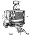
- Fig. 1 shows an air-cooled, mobile, super-silenced screw compressor, which is driven by a diesel engine as a drive unit.
- the mobile compressor is arranged on a single-axle chassis 32.
- On the chassis 32 there is a box-shaped structure 34 which receives an air-cooled diesel engine and an oil-cooled screw compressor.
- the front part of the structure 34 forms a supply air shaft, in which an air-cooled aftercooler 24 including a condensate separator and an automatic condensate drain is arranged.
- an intake filter 36 is arranged above the structure 34. This special arrangement outside the interior of the system removes the compression and combustion air from the atmosphere and not from the interior.
- the compression and combustion temperatures are about 5 ° C lower and the cooling air flow is greater. There are also lower levels of dust in the atmospheric air because the suction point is moved upwards.
- the compressed air flow is through air baffles, which are in the head part of the condensate separator are brought into a rotating movement. Due to the different specific weights, the condensate drops collect on the inner wall of the condensate separator and flow from there down into a condensate collector, which opens depending on the condensate level by an automatic float circuit and discharges the condensate to the outside via a hose line.
- An additional spring-loaded outlet valve opens each time the compressor is regulated to allow any condensate to enter the cooler or piping system.
- connection tap for a breathing air hose with which a worker, for example when sandblasting, can be supplied with clean and cooled breathing air.
- the compressed air is then passed through a heat exchanger which is arranged in the exhaust area of the drive unit, in particular a diesel engine.
- the compressed air is heated, for example, in the form of a tube bundle heat exchanger, for example to about 60 ° C. above the initial temperature.
- the relative humidity is reduced from about 70% to about 10%.
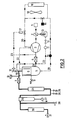
- FIG. 2 The specific structure of an air-cooled compressor according to the invention results from the diagram of FIG. 2 in conjunction with the list of reference symbols below.
- the air is drawn in via an air filter 1 and fed to the compressor 3.
- a throttle valve 2 In the connecting line between the air filter 1 and the compressor 3 there is a throttle valve 2 with an actuating cylinder 13.
- a check valve 4 In the oil-air line 21 between the compressor 3 and the oil tank 5 with an oil separator 6 there is a check valve 4.
- the aftercooler 24 is followed by the condensate separator 29.
- a regulating outlet valve 25 and an intermittent blow-off valve 26 arranged, each open when regulating the compressor 3 or when it is suspended and ensure that the condensate is drained to avoid freezing.
- the condensate collecting due to the condensate separator 29 is drained down via an automatic condensate drain 27.
- a breathing air connection tap 28 is connected to the compressed air line.
- the compressed air line itself leads through a heat exchanger 30 to the connection tap 31 for the connection of the compressed air operated tool or the like.
- a safety valve 9 is connected to the oil container 5.
- the oil of the oil container 5 intended for cooling the compressor 3 is guided via the oil line 20 and an oil filter 14 through an oil cooler 16 which is acted upon by a fan 18.
- a control valve controlled by a thermostat 15 lies in a bypass to the oil cooler 16.
- the control line 23 also leads to a blow-off valve 10 in the air line 19 immediately after the fine oil separator 6.
- a control line 23 also leads via a filter and water separator 11 and a control valve 12 to the actuating cylinder 13.
- the fine oil separator 6 is also via a Oil suction line 22 connected to the compressor 3.
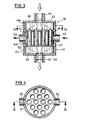
- the heat exchanger 30 has a tubular housing 41 which is closed by means of an upper cover 42 and a lower cover 43.
- the tubular housing 41 here consists of three tubular sections 41a, 41b, 41c.
- the covers 42, 43 are each provided with connecting pieces 44, 45.
- In the central region of the interior of the housing two intermediate walls 46, 47 are drawn in, so that an inflow chamber 48 is formed above the upper intermediate wall and an outflow chamber 49 is formed below the lower intermediate wall 47.
- a cross-flow chamber 50 extends between the intermediate walls 46, 47.
- heat exchanger tubes are arranged parallel to the longitudinal axis of the heat exchanger 30, one of which is designated 51.
- the heat exchanger tubes 51 are inserted into openings which are provided in the intermediate walls 46, 47 and are arranged in alignment. The ends of the heat exchanger tubes 51 are flush with the partitions 46, 47. In the area of the cross-flow chamber 50, connection pieces 52, 53 are provided on the tubular part of the housing 41 on the outside, via which the compressed air is supplied or discharged.
- the entire heat exchanger 30 is designed as a welded construction using simple tubular parts.
- the connecting pieces 44, 45 (diameter d) and the inflow chambers 48, 49 and the heat exchanger tubes 51 and their number are dimensioned so that the permissible exhaust gas pressure of the respective engine brands is not exceeded.
- the dimensioning of the tubular housing part 40 (diameter D) and the connecting piece 52, 53 for the compressed air and the free passage cross section within the cross-flow chamber 50 is selected so that the maximum pressure resistance is about 0.7 bar.
Landscapes
- Engineering & Computer Science (AREA)
- Physics & Mathematics (AREA)
- Thermal Sciences (AREA)
- Chemical & Material Sciences (AREA)
- Mechanical Engineering (AREA)
- General Engineering & Computer Science (AREA)
- Analytical Chemistry (AREA)
- General Chemical & Material Sciences (AREA)
- Oil, Petroleum & Natural Gas (AREA)
- Chemical Kinetics & Catalysis (AREA)
- Compressor (AREA)
- Applications Or Details Of Rotary Compressors (AREA)
Applications Claiming Priority (2)
| Application Number | Priority Date | Filing Date | Title |
|---|---|---|---|
| DE3601816 | 1986-01-22 | ||
| DE19863601816 DE3601816A1 (de) | 1986-01-22 | 1986-01-22 | Luftgekuehlter, insbesondere fahrbarer kompressor |
Publications (2)
| Publication Number | Publication Date |
|---|---|
| EP0230940A2 true EP0230940A2 (fr) | 1987-08-05 |
| EP0230940A3 EP0230940A3 (fr) | 1987-10-14 |
Family
ID=6292373
Family Applications (1)
| Application Number | Title | Priority Date | Filing Date |
|---|---|---|---|
| EP87100588A Withdrawn EP0230940A3 (fr) | 1986-01-22 | 1987-01-17 | Compresseur d'air equipé d'un dispositif de deshumidification |
Country Status (2)
| Country | Link |
|---|---|
| EP (1) | EP0230940A3 (fr) |
| DE (1) | DE3601816A1 (fr) |
Cited By (5)
| Publication number | Priority date | Publication date | Assignee | Title |
|---|---|---|---|---|
| GB2275508A (en) * | 1993-02-24 | 1994-08-31 | Ingersoll Rand Co | An apparatus and method for disposing of liquid effluent separated from a fluidcompression system |
| CN103277312A (zh) * | 2013-06-24 | 2013-09-04 | 北京复盛机械有限公司 | 一种新型螺杆空气压缩机 |
| EP1947348A3 (fr) * | 2006-10-24 | 2014-09-17 | FlexEnergy Energy Systems, Inc. | Système de compression de carburant doté d'un réchauffement interne pour la suppression du point de rosée |
| CN110230856A (zh) * | 2019-05-31 | 2019-09-13 | 河南新野纺织股份有限公司 | 一种纺织厂房空压空调系统 |
| WO2021260465A1 (fr) * | 2020-06-26 | 2021-12-30 | Atlas Copco Airpower, Naamloze Vennootschap | Échangeur de chaleur et procédé de fabrication d'un tel échangeur de chaleur |
Families Citing this family (4)
| Publication number | Priority date | Publication date | Assignee | Title |
|---|---|---|---|---|
| DE4313574A1 (de) * | 1993-04-26 | 1994-10-27 | Leobersdorfer Maschf | Verfahren zur Abscheidung von Kondensat aus Hochdruckluft |
| DE10153459B9 (de) * | 2001-10-30 | 2004-09-09 | Kaeser Kompressoren Gmbh | Anordnung zur Steuerung des Kühlfluidstroms in Kompressoren |
| CN104990163A (zh) * | 2015-07-02 | 2015-10-21 | 沪东重机有限公司 | 用于船用柴油机的除湿防锈装置 |
| CN111085071A (zh) * | 2019-12-31 | 2020-05-01 | 武昌船舶重工集团有限公司 | 一种移动式高压空压机油污气体处理装置及高压空压机 |
Family Cites Families (11)
| Publication number | Priority date | Publication date | Assignee | Title |
|---|---|---|---|---|
| DE7522395U (de) * | 1975-11-06 | Sullair Europe Corp | Schra ubenkompressoreinheit | |
| US2759709A (en) * | 1953-09-29 | 1956-08-21 | Gen Motors Corp | Combination heater and muffler |
| US3050954A (en) * | 1960-05-06 | 1962-08-28 | Edwin H Royse | Moisture condenser |
| US3203196A (en) * | 1963-05-10 | 1965-08-31 | Kramer Trenton Co | Air conditioning system with frost control |
| US3585808A (en) * | 1969-02-17 | 1971-06-22 | Deltech Eng Inc | Method and apparatus for drying compressed gases |
| FR2341342A1 (fr) * | 1976-02-23 | 1977-09-16 | Josse Luc | Installation et procede de sechage d'air humide |
| JPS5758428U (fr) * | 1980-09-19 | 1982-04-06 | ||
| US4359879A (en) * | 1980-12-31 | 1982-11-23 | Diversified Air Products, Inc. | Refrigeration system and novel heat exchanger therefor |
| GB2138553A (en) * | 1983-04-14 | 1984-10-24 | Pentagon Radiators | Apparatus for conditioning compressed gas |
| NL8401494A (nl) * | 1984-05-09 | 1985-12-02 | Josef Johannes Theresia Rompa | Koeldroger voor perslucht. |
| NL8401592A (nl) * | 1984-05-17 | 1985-12-16 | Josef Johannes Theresia Rompa | Koeldroger, in het bijzonder voor perslucht. |
-
1986
- 1986-01-22 DE DE19863601816 patent/DE3601816A1/de not_active Withdrawn
-
1987
- 1987-01-17 EP EP87100588A patent/EP0230940A3/fr not_active Withdrawn
Cited By (8)
| Publication number | Priority date | Publication date | Assignee | Title |
|---|---|---|---|---|
| GB2275508A (en) * | 1993-02-24 | 1994-08-31 | Ingersoll Rand Co | An apparatus and method for disposing of liquid effluent separated from a fluidcompression system |
| GB2275508B (en) * | 1993-02-24 | 1995-07-05 | Ingersoll Rand Co | An apparatus and method for disposing of liquid effluent from a fluid system |
| EP1947348A3 (fr) * | 2006-10-24 | 2014-09-17 | FlexEnergy Energy Systems, Inc. | Système de compression de carburant doté d'un réchauffement interne pour la suppression du point de rosée |
| CN103277312A (zh) * | 2013-06-24 | 2013-09-04 | 北京复盛机械有限公司 | 一种新型螺杆空气压缩机 |
| CN110230856A (zh) * | 2019-05-31 | 2019-09-13 | 河南新野纺织股份有限公司 | 一种纺织厂房空压空调系统 |
| WO2021260465A1 (fr) * | 2020-06-26 | 2021-12-30 | Atlas Copco Airpower, Naamloze Vennootschap | Échangeur de chaleur et procédé de fabrication d'un tel échangeur de chaleur |
| BE1028438B1 (nl) * | 2020-06-26 | 2022-02-03 | Atlas Copco Airpower Nv | Warmtewisselaar en werkwijze voor het vervaardigen van een dergelijke warmtewisselaar |
| US12209824B2 (en) | 2020-06-26 | 2025-01-28 | Atlas Copco Airpower, Naamloze Vennootschap | Heat exchanger and method for manufacturing such a heat exchanger |
Also Published As
| Publication number | Publication date |
|---|---|
| DE3601816A1 (de) | 1987-07-23 |
| EP0230940A3 (fr) | 1987-10-14 |
Similar Documents
| Publication | Publication Date | Title |
|---|---|---|
| DE3836643C2 (fr) | ||
| WO2006087062A1 (fr) | Moteur a combustion interne turbocompresse | |
| DE10250384A1 (de) | Kühl- bzw. Kältemittelkondensator | |
| DE3726332C1 (de) | Ansaugleitungsteil einer Brennkraftmaschine | |
| EP0230940A2 (fr) | Compresseur d'air equipé d'un dispositif de deshumidification | |
| CH684020A5 (de) | Trockenlaufender Hubkolben-Kompressor. | |
| DE2400325A1 (de) | Mit oeleinspritzung arbeitender kreiselkompressor | |
| DE69516940T2 (de) | Sammler für eine Klimaanlage | |
| CH651378A5 (en) | Ventilation device for a room, with two separate flow paths for aerating and deaerating | |
| DE2700893C2 (de) | Kältemittelkreislauf für eine Wärmepumpe mit einem parallelepipedförmigen Gehäuse | |
| EP2256447B1 (fr) | Dispositif de condensateur pour une installation de refroidissement | |
| DE2626788A1 (de) | Kondensatoranlage, insbesondere vorrichtung zum kondensieren des abdampfes eines kraftwerkes | |
| EP0050770B1 (fr) | Unité de compression enfermée dans une enceinte | |
| DE8601519U1 (de) | Luftgekühlter, insbesondere fahrbarer Kompressor | |
| EP2708745B1 (fr) | Compresseur à pistons à plusieurs étages doté de soupapes de ralenti pour la réalisation d'une fonction de ralenti | |
| DE102004036037B4 (de) | Kraftfahrzeug | |
| EP1730464B1 (fr) | Dispositif de refroidissement | |
| EP1557308A2 (fr) | Dispositif pour le refroidissement d'air d'un espace de véhicule et un véhicule avec un tel dispositif | |
| DE19730188A1 (de) | Vorrichtung zum Vermeiden des Wassereintritts in ein Luftfiltergehäuse einer Brennkraftmaschine | |
| DE202011102503U1 (de) | Wärmepumpenanlage | |
| DE10025325B4 (de) | Akkumulator für ein Klimaanlagensystem | |
| DE60005709T2 (de) | Fahrzeugklimaanlage | |
| DE102017201898A1 (de) | Abscheideeinrichtung | |
| DE19650033A1 (de) | Baugruppe für eine Verbrennungskraftmaschine | |
| DE3017778A1 (de) | Vorrichtung zum reinigen von abgasen und verunreinigten daempfen |
Legal Events
| Date | Code | Title | Description |
|---|---|---|---|
| PUAI | Public reference made under article 153(3) epc to a published international application that has entered the european phase |
Free format text: ORIGINAL CODE: 0009012 |
|
| AK | Designated contracting states |
Kind code of ref document: A2 Designated state(s): AT BE CH DE ES FR LI LU NL |
|
| PUAL | Search report despatched |
Free format text: ORIGINAL CODE: 0009013 |
|
| AK | Designated contracting states |
Kind code of ref document: A3 Designated state(s): AT BE CH DE ES FR LI LU NL |
|
| 17P | Request for examination filed |
Effective date: 19880412 |
|
| STAA | Information on the status of an ep patent application or granted ep patent |
Free format text: STATUS: THE APPLICATION IS DEEMED TO BE WITHDRAWN |
|
| 18D | Application deemed to be withdrawn |
Effective date: 19890801 |
|
| RIN1 | Information on inventor provided before grant (corrected) |
Inventor name: ENGELKE, PETERC/O KEIL & SCHAAFHAUSEN |