EP0232505A1 - Dispositif de stockage magnétique à milieu d'enregistrement à magnétiser perpendiculairement - Google Patents
Dispositif de stockage magnétique à milieu d'enregistrement à magnétiser perpendiculairement Download PDFInfo
- Publication number
- EP0232505A1 EP0232505A1 EP86117074A EP86117074A EP0232505A1 EP 0232505 A1 EP0232505 A1 EP 0232505A1 EP 86117074 A EP86117074 A EP 86117074A EP 86117074 A EP86117074 A EP 86117074A EP 0232505 A1 EP0232505 A1 EP 0232505A1
- Authority
- EP
- European Patent Office
- Prior art keywords
- magnetic
- layer
- leg
- storage device
- trailing
- Prior art date
- Legal status (The legal status is an assumption and is not a legal conclusion. Google has not performed a legal analysis and makes no representation as to the accuracy of the status listed.)
- Ceased
Links
Images


Classifications
-
- G—PHYSICS
- G11—INFORMATION STORAGE
- G11B—INFORMATION STORAGE BASED ON RELATIVE MOVEMENT BETWEEN RECORD CARRIER AND TRANSDUCER
- G11B5/00—Recording by magnetisation or demagnetisation of a record carrier; Reproducing by magnetic means; Record carriers therefor
- G11B5/127—Structure or manufacture of heads, e.g. inductive
- G11B5/1278—Structure or manufacture of heads, e.g. inductive specially adapted for magnetisations perpendicular to the surface of the record carrier
-
- G—PHYSICS
- G11—INFORMATION STORAGE
- G11B—INFORMATION STORAGE BASED ON RELATIVE MOVEMENT BETWEEN RECORD CARRIER AND TRANSDUCER
- G11B5/00—Recording by magnetisation or demagnetisation of a record carrier; Reproducing by magnetic means; Record carriers therefor
Definitions
- the invention relates to a magnetic memory device with a thin-film magnetic head built up in layers on a non-magnetic substrate and with a recording medium which is provided with a magnetizable storage layer made of a material of predetermined coercive field strength, into which information is provided along a track by vertical (vertical) Magnetization of this layer are to be inscribed, the magnetic head containing a ring-like magnetic guide body guiding the magnetic flux and having two magnetic legs, each of which has at least one magnetic layer with predetermined magnetic behavior, whose magnetic poles facing the recording medium are arranged one behind the other in the (relative) direction of movement of the head, a gap having a predetermined width being formed, and - The outside of the pole area delimit a space through which the windings of a write and / or read coil winding extend.
- a corresponding magnetic head of such a storage device can be found, for example, in EP 0 012 912 A1.
- This head can be used to store information by perpendicular magnetization of a corresponding recording medium.
- This principle is generally known (see, for example, "IEEE Transactions on Magnetics", Vol. MAG-16, No. 1, January 1980, pages 71 to 76, or Vol. MAG-20, No. 5, Sept. 1984, pages 657 to 662 and 675 to 680).
- the one for this often as a vertical magnetisie
- the principle to be provided for the recording media can be in the form of rigid magnetic storage disks, flexible individual disks (floppy discs) or magnetic tapes.
- These media each have at least one magnetizable storage layer of predetermined thickness, which contains a magnetically anisotropic material of predetermined coercive field strength, in particular made of a CoCr alloy.
- the axis of the so-called slight magnetization of this layer is oriented perpendicular to the surface of the medium.
- individual pieces of information can then be written as bits in successive sections along a track by appropriate magnetization of the storage layer.
- the combined write and read magnetic heads known for the principle of so-called longitudinal magnetization cannot readily be adopted for vertical magnetization.
- these heads whose magnetic guide bodies formed from magnetic legs generally have a ring head-like shape, the magnetic flux guidance which is also aimed at with the principle of vertical magnetization can be achieved in a closed circuit with as little magnetic resistance as possible.
- This known magnetic head has a so-called guide body for guiding the magnetic flux.
- This magnetic guide body comes with two Magnetic legs formed, each consisting of at least one layer of a magnetic material with predetermined specific magnetic properties or magnetic behavior such as a special NiFe alloy (eg "Permalloy”: trademark of "Bell Telephone Manufacturing Comp.”). With their end regions facing the recording medium, two magnetic poles are formed, which, viewed in the direction of movement of the head, are arranged one behind the other and with a predetermined small gap width to one another.
- the writing field should be as asymmetrical as possible in order to raise the vertical component of this field at the trailing edge of the writing magnetic pole and to weaken the vertical component of opposite polarity at the leading edge of the other magnetic pole.
- the magnetic field at the trailing edge is generally somewhat weaker than the magnetic field at the leading edge.
- the requirements mentioned with regard to large writing fields and high resolution should at least be largely taken into account.
- This object is achieved in that - The magnetic behavior of the at least one magnetic layer of the magnetic leg trailing in the direction of movement, at least in its end region forming the magnetic pole, is different from that of the at least one magnetic layer of the leading magnetic leg at least in its end region forming the magnetic pole and -
- the coercive field strength of the material of the storage layer of the recording medium is chosen to be sufficiently high that overwriting of the storage layer of the recording medium with the magnetic field to be produced on the magnetic pole of the trailing magnetic leg is at least largely excluded.
- the characteristic magnetic behavior of the respective magnetic layers is to be regarded, at least in their end regions forming a magnetic pole, in particular the magnetic resistance of the layer or the saturation magnetization of the layer material.
- the advantages associated with this configuration of the magnetic storage device are to be seen in particular in the fact that, when writing, the magnetization of the magnetic layer of the trailing leg is reduced in its pole area compared to the magnetization of the magnetic layer of the leading leg and therefore the vertical component of the magnetic field of the trailing leg is correspondingly smaller is as the vertical field of the leading magnetic pole.
- the magnetic head of the memory device according to the invention thus writes, due to the different magnetic behavior of its legs, in contrast to known heads with its leading magnetic pole.
- the magnetic head behaves like a common thin-film ring head when reading due to the known smaller fields, which registers a very sharp magnetic transition with a correspondingly large reading voltage. It is also particularly advantageous that the gap width in the magnetic head of the memory device according to the invention is very small without significantly impairing the writing properties can be kept and that the maximum achievable bit density is accordingly large.
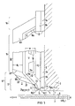
- Figure 1 schematically illustrates an embodiment of a memory device according to the invention.
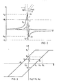
- Figure 2 shows a diagram of the vertical magnetic field component generated with the magnetic head of this memory device according to Figure 1.
- the corresponding magnetization ratios are indicated in a further diagram in FIG.
- FIG. 4 shows another exemplary embodiment of a storage device according to the invention, while in FIG. 5 the diagram shows the vertical magnetic field component generated with the magnetic head of this storage device.
- the magnetic head of a first storage device which is shown only partially as a longitudinal section in FIG. 1, it is assumed that ring-head-like embodiments known per se with a layered structure, such as have been developed for the principle of vertical (vertical) magnetization (see, for example, the aforementioned EP -A1).
- the magnetic head generally designated 2
- both a write and a read function should be performed.
- This head is located on a flat side of a non-magnetic substrate 3, which forms the end face or in particular the back side of a common element, also referred to as a missile, and which is not shown in the figure.
- the magnetic head is to be guided relative to a recording medium A known per se at a low altitude f, the relative direction of movement of the recording voltage medium with respect to the magnetic head is indicated by an arrowed line labeled v.
- the flight height f established between the at least one flight skid, the underside of the head 2 facing the recording medium A and the recording medium is, for example, only a few tenths of a micrometer.
- the recording medium A for example a magnetic disk, has a storage layer 6 which is oriented vertically (vertically) and has a predetermined thickness D.
- the material of the storage layer, for which a CoCr alloy is selected, for example, should have a predetermined high value of the (vertical) coercive field strength H c of, for example, more than 20 kA / m, preferably more than 60 kA / m (cf. e.g. EP 0 120 413 A1 or EP 0 054 269 A2).
- the storage layer 6 can advantageously also on at least one further soft magnetic layer, e.g. from a special NiFe alloy or from amorphous CoZr or CoHf, which may also contain ternary additives such as made of Ni or Nb.
- This sub-layer is designated 7 in the figure.
- the magnetic head 2 contains a magnetic head 8 which guides the magnetic flux and is similar to a ring head and has two magnetic legs 9 and 10 . These legs are largely and in particular oriented in their end regions 11 and 12, which face the recording medium A and form magnetic poles Mp1 and Mp2, at least approximately perpendicular to the surface of the recording medium.
- the end regions are understood to mean the thin end piece of a magnetic leg, which has an at least largely uniform transverse extension or thickness or which is not reinforced by any further layers.
- the end regions 11 and 12 are spatially separated by an air gap 13 which has an advantageously low longitudinal, ie in, in the region of the magnetic poles Mp1 and Mp2
- the direction of movement v of the magnetic head has a width g of less than 1 ⁇ m, in particular less than 0.5 ⁇ m, preferably less than 0.25 ⁇ m.
- the distance between the two magnetic legs 9 and 10 is widened with respect to this gap width g, for example by extending the rearward, ie trailing, magnetic leg 10 with respect to the direction of movement v to a greater width w with respect to the front, level and the magnetic leg 9 facing the substrate 3 leads.
- the magnetic leg 10 is attached in a known manner in a connecting area 16 to the magnetic leg 9 , so that the ring-head-like shape of the guide body 8 results.
- At least one flat coil winding 18 extends through the intermediate space 17 formed between the two magnetic legs 9 and 10 in the central region 15 and can serve both as a writing and as a reading coil.
- This winding which is only indicated with a single layer 18a in the figure, can also be constructed in multiple layers and generally has a relatively large number of turns. A relatively large write current I can flow through them.
- the two magnetic legs 9 and 10 of the magnetic head 2 are each formed by at least one magnetic layer 9a or 10a with a layer thickness d1 or d2.
- the respective layer thickness is understood to mean the extent of the corresponding layer in the direction of movement v in the respective pole region 11 or 12.
- these magnetic layers are to have different magnetic resistances at least in their pole regions 11 and 12, the layer 10a of the magnetic leg 10 trailing in the relative direction of movement having the substantially higher one, preferably by at least one Factor 2 should have higher magnetic resistance R M2 .
- the lower magnetic resistance of the layer 9a of the leading magnetic leg 9 is denoted by R M1 .
- the size of the magnetic resistance of the respective magnetic layer depends on the reversible permeability ⁇ r and the geometry of the respective layer.
- the reversible permeability of the layers can be determined by the choice of material and the manufacturing conditions, for example in sputtering.
- a material with a reversible permeability ⁇ r1 which is greater than the reversible permeability ⁇ r2 of the magnetic layer 10a of the trailing magnetic leg is preferably selected for the magnetic layer 9a of the leading magnetic leg 9 .
- the larger permeability ⁇ r1 should have a value above 1000, preferably above 3000, while the value of the lower permeability ⁇ r2 should generally be below 1000 and is, for example, approximately 500.
- Materials are preferably chosen whose reversible permeabilities differ by at least a factor of 3.
- the magnetic resistance of these layers can additionally be varied by a suitable choice of the layer thicknesses d 1 and d 2 of the magnetic layers 9a and 10a.
- These layer thicknesses should be selected to be less than 2 ⁇ m, in particular less than 1 ⁇ m, preferably less than 0.7 ⁇ m.
- a value of the thickness d 1 is provided for the magnetic layer 9 a of the leading magnetic leg 9 that is greater than the value of the thickness d 2 of the magnetic layer 10 a of the trailing magnetic leg 10 .
- bit densities above 30 kFCI kilo flux changes per inch
- d1 ⁇ 0.6 ⁇ m, d2 ⁇ 0.4 ⁇ m and g ⁇ 0.25 ⁇ m can be selected.
- the flight height f and the thickness D of the CoCr storage layer 6 should in this case satisfy the inequality f + D ⁇ 0.5 ⁇ m.
- the thickness of the soft magnetic underlayer 7 should be the thickness of the thicker of the two magnetic poles Mp1, Mp2 not significantly below.
- each of the magnetic legs 9 and 10 can be provided with an additional, relatively thick magnetic layer 9b or 10b outside the respective end region 11 or 12, these layers in particular the central region 15 of the magnetic guide body 8 with the Cover coil winding 18.
- the thicknesses of these additional layers 9b and 10b are denoted by d3 and d4.
- the layers 9b and 10b do not extend as far as the respective magnetic poles Mp1 or Mp2, but each end a predetermined distance away from them. In this way, you define the upper limits of the end regions 11 and 12. Accordingly, the end region 12 of the magnetic leg 10 begins at the point at which the outside of the magnetic layer 10b denoted by 20 abuts the outside of the magnetic layer 10a.
- the outside of the magnetic layer 10b can also end further withdrawn, so that the end region of the magnetic layer 10a is then correspondingly expanded.
- the additional layers 9b and 10b can thus advantageously serve to influence the magnetic resistance of the respective magnetic leg and can also be used for the desired asymmetry of the field profile of the writing field Outside 20, 20 ', 20 "or different dimensions of the magnetic layer 10b with respect to the recording medium A on the read-write behavior of the magnetic head 2 a strong influence. For example, shorter legs lead to better writing fields, but to smaller reading amplitudes.
- Another possibility for increasing the magnetic resistance of the trailing magnetic leg 10 is thereby given that a reduction in cross section increasing the magnetic resistance is provided in the magnetic layer 10a.
- This reduction in cross section can preferably be at the edge of the end region 12 or 12 ′ or 12 ′′ facing the central region 15.
- such an increase in resistance can be obtained by, for example, etching the additional magnetic layer 10b of the leg 10 in an ion beam etching is produced by overetching in the magnetic layer 10a of this leg forming the magnetic pole Mp2
- the outline of this etching trench is indicated in the figure by a dashed line 22.
- the position of the read / write coil winding 18 also has an influence on the saturation behavior of the end pieces 11 and 12 or 12 ′, 12 ′′ of the magnetic legs 9 or 10 with the poles Mp1 and Mp2 and thus on the magnetic fields that can be generated.
- the magnetic fields are all the more so The closer this winding is to the gap 13.
- the position of the read / write coil winding 18 offers a further possibility to influence the amplitude as well as the asymmetry of the vertical field.
- the layers 9a, 9b and 10a, 10b come in particular FeNi alloys such as from “Permalloy” or amorphous CoZr or CoHf alloys in question. If necessary, the alloy partners of these amorphous alloys may also have other, e.g. ternary partners.
- the magnetic storage device Due to the different magnetic resistance ratios to be set in this way in the two magnetic legs 9 and 10, in particular in their corresponding end regions 11 and 12, 12 ', 12 ", it can then be achieved that practically the write function is performed only with the magnetic pole Mp1 of the leading magnetic leg 9 .
- the magnetic storage device also provides that the coercive field strength H c of the storage layer 6 of the Recording medium A is chosen so high that the magnetic field of the trailing pole Mp2 is no longer sufficient to re-magnetize the written information.
- the corresponding field relationships can be read in more detail from the diagram in FIG. 2.
- the absolute value of the coercive field strength H c should be, for example, at least 20 kA / m, preferably at least 60 kA / m.
- This diagram shows the field strength H of the magnetic field generated by the two magnetic poles Mp1 and Mp2 as a function of the extension x of the magnetic head pointing in the direction of movement v.
- the contours of these magnetic poles are only indicated schematically in the diagram, not to scale.
- the resulting field strength H, plotted in the ordinate direction, is measured on the surface of the recording medium A in the normal direction (y direction).
- the field strength curve H y has a pronounced (positive) maximum which can essentially be ascribed to the leading magnetic pole Mp1 and which clearly exceeds the corresponding (positive) switching field "+ H c " of the storage layer 6.
- This switching field “+ H c ”, indicated by a dashed line, is understood to mean the magnetic field which is just sufficient to effect a reversal of magnetization in the storage layer 6. Ideally, this switching field corresponds to the corresponding coercive field strength of the material of the storage layer; in general, however, it deviates slightly from this Factor. In the diagram, however, the ideal case is assumed in which the switching field is set equal to the coercive field strength H c . As can also be seen from the diagram, the field strength curve H y between the vertex S1 to be ascribed to the leading magnetic pole Mp1 with H s1 and the intersection P with the switching field "+ H c " advantageously shows a very steep course.
- a material should therefore be selected for the storage layer 6 of a recording medium A of the storage device according to the invention which has a correspondingly high switching field resulting in a coercive field strength H c .
- Corresponding materials for this are generally known (cf. for example EP 0 120 413 or EP 0 054 269).
- the field strength curve H x of the (longitudinal) field component formed in the direction of movement v is entered in the diagram by a dash-dotted line.
- a magnetic head 2 was assumed whose write current I is a maximum H s1 of the magnetic pole Mp1 of the leading magnetic leg and a minimum H s2 of the magnetic pole Mp2 of the rear magnetic leg.
- a write current with the direction of flow reversed, a corresponding field profile is obtained which is however mirrored to the x-axis.
- the magnetization ratios corresponding to the curve in FIG. 2 are indicated in the diagram in FIG. 3.
- a recording medium with only an ideal, vertical thin storage layer 6, a so-called single layer is assumed.
- the sheared magnetization curve is shown in this figure, the magnetization M being plotted on the ordinate and the field strength H in arbitrary units on the abscissa.
- the position to be written is on the hysteresis curve at point PO .
- the magnetic head moving relative to the storage layer then first magnetizes with its leading magnetic pole Mp1 with the maximum write field strength
- the vertical field is then reversed between the two magnetic poles Mp1 and Mp2, the point P2 being crossed on the ordinate, and finally takes the negative value of the amount
- the point P3 is reached on the magnetization curve.
- the subsequent reversal of the field to zero completes the magnetization reversal and thus the writing process.
- the corresponding point on the ordinate is designated P4. It coincides with the point P2. Because the size of the read signal is proportional to the magnetization at this point P4, the vertical field of the outgoing magnetic pole Mp2 must satisfy the inequality:
- This formulation of the inequality also takes into account the fact that IH s1 become negative and H s2 positive when the current flow direction of the write current is reversed.
- FIG. 3 was based on a recording medium A with a single layer as the storage layer 6.
- a double-layer storage medium which, in addition to the storage layer 6, which consists in particular of CoCr, also has a soft magnetic base 7, e.g. from NiFe, CoZr, CoHf, etc., must also be considered that all critical dimensions shown in Figure 1: g, (d1 + g / 2), (d2 + g / 2), (f + D) of the depend on the minimum flux change wavelength (cf. "IEEE Transactions on Magnetics", Vol. MAG-19, No. 5, 1983, pages 1611 to 1613).
- the magnetic head of a further storage device according to the invention which is shown only partially as a longitudinal section in FIG. 4, has a structure which largely corresponds to the structure of the head 2 shown in FIG. Corresponding parts are therefore provided with the same reference symbols in the figures.
- the two magnetic legs 9 and 10 of this magnetic head designated 24 are also each through at least one magnetic layer 9a or 10a formed with a layer thickness d1 or d2.
- the measures according to the invention with regard to the magnetic behavior of the individual magnetic legs should not relate to their magnetic resistance, but to the saturation magnetization of their material. Accordingly, in the embodiment according to FIG.
- the material of the layer 9a of the magnetic leg 9 leading in the relative direction of movement v should have the higher saturation magnetization Ms 1.
- the lower saturation magnetization of the material of the layer 10a of the trailing magnetic leg 10 is denoted by Ms2.
- the values of the saturation magnetizations Ms1 and Ms2 should differ in particular by a factor of at least 1.4. Alloys such as "permalloy” or amorphous CoZr or CoHF alloys are particularly suitable as materials for the layers 9a and 10a.
- the larger saturation magnetization Ms1 should have a value above 1000 kA / m, preferably above 1100 kA / m, while the value of the smaller saturation magnetization Ms2 is, for example, below 900 kA / m, preferably below 800 kA / m.
- “Permalloy” has a saturation magnetization in the order of 800 kA / m, while the saturation magnetization of the binary amorphous materials mentioned is in the order of 1100 kA / m.
- ternary amorphous alloys with a high saturation magnetization Ms 1 come into question.
- the saturation magnetizations Ms of the individual layers can be influenced in a known manner by the production conditions or by the choice of the alloy composition.
- each of the magnetic legs 9 and 10 can be provided with an additional, relatively thick magnetic layer 9b or 10b outside the region occupied by the end regions 11 and 12, these layers in particular the central region 15 with the coil winding Cover 18.
- the thicknesses of these additional layers 9b and 10b are denoted by d3 and d4.
- These additional layers can advantageously serve to reduce the magnetic resistance in the magnetic guide body 8 and can also be used for the desired asymmetry of the field profile of the writing field.
- the layer thickness d 1 of the magnetic layer 9 a of the leading magnetic leg 9 with the high saturation magnetization Ms 1 may optionally be greater than the layer thickness d 2 of the magnetic layer 10 a with a lower saturation magnetization Ms 2 of the trailing magnetic leg 10 .
- a material can advantageously be provided for the additional magnetic layer 9b of the leading magnetic leg 9 , the saturation magnetization Ms3 of which is greater than the saturation magnetization Ms4 of the material of the additional magnetic layer 10b of the trailing magnetic leg 10 .
- the reversible permeability ⁇ r of the materials is used as a basis.
- a material for the magnetic layer 9a delimiting the gap 13 of the leading magnetic leg 9 the permeability ⁇ r1 of which is greater than the permeability ⁇ r2 of the magnetic layer 10a of the trailing magnetic leg 10 delimiting the gap 13.
- the layer 10a can no longer absorb additional flux at high write currents I, a further increase in the write current I leads to the magnetic layer 9a of the other magnetic leg 9 of material with the substantially greater saturation magnetization Ms1 performing the write function.
- the magnetic fields emerging from the storage layer 6 of the recording medium A are known to be relatively small, so that they cannot drive the magnetic layer 10a from the material with the lower saturation magnetization Ms2 into saturation. Consequently, the reading function is also carried out with this magnetic layer. But that means that when reading the magnetic head 24 works as an ordinary ring head with the known good efficiency.
- this magnetic storage device In order to ensure this characteristic operation of the magnetic head 24 , ie to avoid overwriting information written with the leading magnetic leg 9 with the trailing magnetic leg 10 , this magnetic storage device according to the invention also provides that the coercive field strength H c of the storage layer 6 of the recording medium A is chosen so high that the magnetic field of the trailing pole Mp2 is no longer sufficient to write to the storage layer 6.
- the corresponding field relationships can be read in more detail from the diagram in FIG. 5.
- the absolute value of the coercive field strength H c for example, be at least 30 kA / m, preferably at least 60 kA / m.
- FIG. 5 shows the field strength H of the magnetic field generated by the two magnetic poles Mp1 and Mp2 as a function of the extension x of the magnetic head pointing in the direction of movement v.
- the field strength is measured on the surface of the recording medium in the normal direction (y direction).
- the contours of the leading pole Mp1 and the trailing pole Mp2 are indicated schematically, not to scale.
- the field strength curve H y has a pronounced (negative) maximum which is essentially attributable to the leading magnetic pole Mp1 and which clearly falls below the corresponding (negative) switching field (-H c ) of the storage layer 6.
- This switching field (-H c ), indicated by a dashed line, is understood to mean the magnetic field which is just sufficient to cause magnetic reversal in the storage layer 6. Ideally, this switching field corresponds to the corresponding coercive field strength of the material of the storage layer; in general, however, it deviates from this by a slight amount. In the diagram, however, the ideal case is assumed in which the switching field is set equal to the coercive field strength H c . As can also be seen from the diagram, the field strength curve between the minimum H min and the intersection S with the switching field (-H c ) advantageously shows a very steep profile.
- a material is to be selected for the storage layer 6 of the recording medium A of the storage device according to the invention which has a coercive field strength H c which results in a correspondingly high switching field.
- Corresponding materials are generally known (cf. for example EP 0 120 413 or 0 054 269).
Landscapes
- Engineering & Computer Science (AREA)
- Manufacturing & Machinery (AREA)
- Magnetic Record Carriers (AREA)
- Magnetic Heads (AREA)
Applications Claiming Priority (4)
| Application Number | Priority Date | Filing Date | Title |
|---|---|---|---|
| DE3545361 | 1985-12-20 | ||
| DE19853545361 DE3545361A1 (de) | 1985-12-20 | 1985-12-20 | Magnetische speichereinrichtung fuer eine senkrechte magnetisierung |
| DE3603903 | 1986-02-07 | ||
| DE19863603903 DE3603903A1 (de) | 1986-02-07 | 1986-02-07 | Magnetische speichereinrichtung mit einem senkrecht zu magnetisierenden aufzeichnungsmedium |
Publications (1)
| Publication Number | Publication Date |
|---|---|
| EP0232505A1 true EP0232505A1 (fr) | 1987-08-19 |
Family
ID=25839159
Family Applications (1)
| Application Number | Title | Priority Date | Filing Date |
|---|---|---|---|
| EP86117074A Ceased EP0232505A1 (fr) | 1985-12-20 | 1986-12-08 | Dispositif de stockage magnétique à milieu d'enregistrement à magnétiser perpendiculairement |
Country Status (2)
| Country | Link |
|---|---|
| US (1) | US4742413A (fr) |
| EP (1) | EP0232505A1 (fr) |
Cited By (9)
| Publication number | Priority date | Publication date | Assignee | Title |
|---|---|---|---|---|
| EP0326904A1 (fr) * | 1988-02-04 | 1989-08-09 | Siemens Aktiengesellschaft | Tête magnétique en film mince à capteur magnétorésistif intégré |
| WO1990007176A1 (fr) * | 1988-12-15 | 1990-06-28 | Siemens Aktiengesellschaft | Tete magnetique a couche mince a parties noyees dans un substrat et son procede de fabrication |
| WO1990007178A1 (fr) * | 1988-12-22 | 1990-06-28 | Siemens Aktiengesellschaft | Tete magnetique a couche mince pour support d'enregistrement a magnetisation verticale |
| US4951166A (en) * | 1987-10-16 | 1990-08-21 | Siemens Aktiengesellschaft | Thin-film magnetic head with layer structure and with pole pieces of varying widths |
| WO1990009658A1 (fr) * | 1989-02-13 | 1990-08-23 | Siemens Aktiengesellschaft | Tete magnetique a couche mince d'enregistrement vertical avec deux poles magnetiques separes par une fente etroite |
| DE3921182A1 (de) * | 1989-06-28 | 1991-01-03 | Siemens Ag | Magnetische datenspeichereinrichtung mit einem in einem substrat versenkte teile enthaltenden duennfilm-magnetkopf |
| EP0315361A3 (fr) * | 1987-10-30 | 1991-01-09 | Seagate Technology, Inc. | Tête magnétique pour système d'enregistrement magnétique perpendiculaire et procédé de fabrication |
| EP0311855A3 (fr) * | 1987-10-16 | 1991-01-30 | Siemens Aktiengesellschaft | Tête magnétique à film mince à structure en couches |
| EP0490669B1 (fr) * | 1990-12-12 | 1996-02-07 | Kabushiki Kaisha Toshiba | Système d'enregistrement magnétique |
Families Citing this family (24)
| Publication number | Priority date | Publication date | Assignee | Title |
|---|---|---|---|---|
| US4819111A (en) * | 1986-08-29 | 1989-04-04 | Magnetic Peripheral Inc. | Thin film head with reduced cross section in the core for causing magnetic saturation in the leading leg's throat area |
| US4839761A (en) * | 1987-07-31 | 1989-06-13 | Seagate Technology, Inc. | Magnetic head for perpendicular magnetic recording system |
| JP2585400B2 (ja) * | 1988-03-23 | 1997-02-26 | 株式会社日立製作所 | 磁気デイスク装置 |
| DE69019416T2 (de) * | 1989-05-01 | 1996-02-29 | Quantum Corp | Magnetische Vorrichtungen mit verbesserten Polen. |
| US5659446A (en) * | 1990-12-12 | 1997-08-19 | Kabushiki Kaisha Toshiba | Magnetic recording system providing a magnetic head having opposite sides for applying different magnetic field strengths to a magnetic recording medium |
| US5452166A (en) * | 1993-10-01 | 1995-09-19 | Applied Magnetics Corporation | Thin film magnetic recording head for minimizing undershoots and a method for manufacturing the same |
| US5559653A (en) * | 1993-12-10 | 1996-09-24 | Yamaha Corporation | Thin film magnetic head having a multilayer upper core |
| US6876519B1 (en) | 1999-09-20 | 2005-04-05 | Seagate Technology Llc | Magnetic recording head including background magnetic field generator |
| WO2001022407A1 (fr) * | 1999-09-20 | 2001-03-29 | Seagate Technology, Llc | Tete d'enregistrement magnetique comprenant un generateur de champ magnetique d'arriere-plan |
| US6898053B1 (en) | 1999-10-26 | 2005-05-24 | Seagate Technology Llc | Perpendicular recording head with trackwidth defined by plating thickness |
| US6560069B1 (en) | 1999-11-29 | 2003-05-06 | Seagate Technology, Llc | Perpendicular recording head defining the trackwidth by material deposition thickness |
| US6646827B1 (en) | 2000-01-10 | 2003-11-11 | Seagate Technology Llc | Perpendicular magnetic recording head with write pole which reduces flux antenna effect |
| US6667848B1 (en) | 2000-01-10 | 2003-12-23 | Seagate Technology Llc | Perpendicular magnetic recording head with means for suppressing noise from soft magnetic underlayer of recording media |
| US6574072B1 (en) | 2000-01-12 | 2003-06-03 | Seagate Technology Llc | Perpendicular magnetic recording head with radial magnetic field generator which reduces noise from soft magnetic underlayer of recording disk |
| JP2001351204A (ja) * | 2000-03-10 | 2001-12-21 | Tdk Corp | 薄膜磁気ヘッドおよびその製造方法 |
| US6693768B1 (en) * | 2000-03-15 | 2004-02-17 | Seagate Technology Llc | Perpendicular magnetic recording head having a flux focusing main pole |
| US6717770B1 (en) | 2000-03-24 | 2004-04-06 | Seagate Technology Llc | Recording head for applying a magnetic field perpendicular to the magnetizations within magnetic storage media |
| US6687085B2 (en) * | 2001-07-17 | 2004-02-03 | Seagate Technology Llc | Perpendicular write head with high magnetization pole material and method of fabricating the write head |
| JP2006079672A (ja) * | 2004-09-07 | 2006-03-23 | Sony Corp | ヘリカルテープシステム |
| JP2007172707A (ja) * | 2005-12-20 | 2007-07-05 | Alps Electric Co Ltd | 垂直磁気記録ヘッド装置 |
| US8200869B2 (en) * | 2006-02-07 | 2012-06-12 | Seagate Technology Llc | Storage system with alterable background behaviors |
| KR100790877B1 (ko) * | 2006-06-08 | 2008-01-03 | 삼성전자주식회사 | 고밀도 기록을 위한 수직 자기 기록 헤드 |
| US8018679B2 (en) * | 2007-12-17 | 2011-09-13 | Hitachi Global Storage Technologies Netherlands B.V. | Perpendicular magnetic recording write head with slanted magnetic write pole |
| CN102753594A (zh) * | 2010-02-02 | 2012-10-24 | 拜耳知识产权有限责任公司 | 多异氰酸酯加聚产物、它的制备方法及其应用 |
Citations (7)
| Publication number | Priority date | Publication date | Assignee | Title |
|---|---|---|---|---|
| US3639699A (en) * | 1970-02-27 | 1972-02-01 | Gen Electric | Magnetic transducer having a composite magnetic core structure |
| DE2658956A1 (de) * | 1976-12-24 | 1978-06-29 | Ibm Deutschland | Vertikales magnetisches informationsaufzeichnungssystem |
| FR2428886A1 (fr) * | 1978-06-13 | 1980-01-11 | Cii Honeywell Bull | Support d'information magnetique a enregistrement perpendiculaire |
| EP0071489A2 (fr) * | 1981-07-30 | 1983-02-09 | Fujitsu Limited | Tête magnétique pour enregistrement ou reproduction perpendiculaire |
| EP0135739A1 (fr) * | 1983-08-19 | 1985-04-03 | Siemens Aktiengesellschaft | Tête magnétique combinée d'écriture et de lecture pour support d'enregistrement à magnétisation verticale |
| GB2149186A (en) * | 1983-11-04 | 1985-06-05 | Control Data Corp | A magnetic transducer head |
| EP0166818A1 (fr) * | 1984-06-04 | 1986-01-08 | Siemens Aktiengesellschaft | Tête magnétique construite en couches pour un milieu d'enregistrement à magnétiser perpendiculairement |
Family Cites Families (13)
| Publication number | Priority date | Publication date | Assignee | Title |
|---|---|---|---|---|
| JPS5284722A (en) * | 1975-12-31 | 1977-07-14 | Fujitsu Ltd | Thin film magnetic head and its production |
| JPS5522276A (en) * | 1978-08-04 | 1980-02-16 | Fujitsu Ltd | Thin-film magnetic head |
| US4219854A (en) * | 1978-12-21 | 1980-08-26 | International Business Machines Corporation | Thin film magnetic head assembly |
| US4190872A (en) * | 1978-12-21 | 1980-02-26 | International Business Machines Corporation | Thin film inductive transducer |
| JPS57100627A (en) * | 1980-12-12 | 1982-06-22 | Teijin Ltd | Manufacture of vertical magnetic recording medium |
| JPS5888812A (ja) * | 1981-11-19 | 1983-05-27 | Matsushita Electric Ind Co Ltd | 磁気ヘツド |
| JPS58199422A (ja) * | 1982-05-18 | 1983-11-19 | Nec Corp | 垂直磁気記録ヘツド |
| JPS5965917A (ja) * | 1982-10-08 | 1984-04-14 | Nec Corp | 垂直磁気記録ヘツド |
| JPS5977625A (ja) * | 1982-10-26 | 1984-05-04 | Ricoh Co Ltd | 磁気記録媒体 |
| JPS59177726A (ja) * | 1983-03-28 | 1984-10-08 | Toshiba Corp | 垂直磁気デイスク記録媒体 |
| JPS59231721A (ja) * | 1983-06-13 | 1984-12-26 | Matsushita Electric Ind Co Ltd | 薄膜垂直記録ヘツド |
| JPS59231717A (ja) * | 1983-06-13 | 1984-12-26 | Matsushita Electric Ind Co Ltd | 垂直記録ヘツド |
| JPS6058511A (ja) * | 1983-09-12 | 1985-04-04 | Hitachi Ltd | 変位測定装置 |
-
1986
- 1986-12-08 EP EP86117074A patent/EP0232505A1/fr not_active Ceased
- 1986-12-15 US US06/941,392 patent/US4742413A/en not_active Expired - Lifetime
Patent Citations (7)
| Publication number | Priority date | Publication date | Assignee | Title |
|---|---|---|---|---|
| US3639699A (en) * | 1970-02-27 | 1972-02-01 | Gen Electric | Magnetic transducer having a composite magnetic core structure |
| DE2658956A1 (de) * | 1976-12-24 | 1978-06-29 | Ibm Deutschland | Vertikales magnetisches informationsaufzeichnungssystem |
| FR2428886A1 (fr) * | 1978-06-13 | 1980-01-11 | Cii Honeywell Bull | Support d'information magnetique a enregistrement perpendiculaire |
| EP0071489A2 (fr) * | 1981-07-30 | 1983-02-09 | Fujitsu Limited | Tête magnétique pour enregistrement ou reproduction perpendiculaire |
| EP0135739A1 (fr) * | 1983-08-19 | 1985-04-03 | Siemens Aktiengesellschaft | Tête magnétique combinée d'écriture et de lecture pour support d'enregistrement à magnétisation verticale |
| GB2149186A (en) * | 1983-11-04 | 1985-06-05 | Control Data Corp | A magnetic transducer head |
| EP0166818A1 (fr) * | 1984-06-04 | 1986-01-08 | Siemens Aktiengesellschaft | Tête magnétique construite en couches pour un milieu d'enregistrement à magnétiser perpendiculairement |
Non-Patent Citations (9)
| Title |
|---|
| PATENT ABSTRACTS OF JAPAN, Band 1, Nr. 145, 25. November 1977, Seite 7380 E 77; & JP-A-52 84 722 (FUJITSU K.K.) 14-07-1977 * |
| PATENT ABSTRACTS OF JAPAN, Band 7, Nr. 188 (P-217)[1333], 17. August 1983; & JP-A-58 88 812 (MATSUSHITA DENKI SANGYO K.K.) 27-05-1983 * |
| PATENT ABSTRACTS OF JAPAN, Band 8, Nr. 171 (P-293)[1608], 8. August 1984; & JP-A-59 65 917 (NIPPON DENKI K.K.) 14-04-1984 * |
| PATENT ABSTRACTS OF JAPAN, Band 8, Nr. 188 (P-297)[1625], 29. August 1984; & JP-A-59 77 615 (HITACHI SEISAKUSHO K.K.) 04-05-1984 * |
| PATENT ABSTRACTS OF JAPAN, Band 8, Nr. 48 (P-258)[1485], 3. März 1984; & JP-A-58 199 422 (NIPPON DENKI K.K.) 19-11-1983 * |
| PATENT ABSTRACTS OF JAPAN, Band 9, Nr. 109 (P-355)[1832], 14. Mai 1985; & JP-A-59 231 717 (MATSUSHITA DENKI SANGYO K.K.) 26-12-1984 * |
| PATENT ABSTRACTS OF JAPAN, Band 9, Nr. 109 (P-355)[1832], 14. Mai 1985; & JP-A-59 231 721 (MATSUSHITA DENKI SANGYO K.K.) 26-12-1984 * |
| PATENT ABSTRACTS OF JAPAN, Band 9, Nr. 190 (P-378)[1913], 7. August 1985; & JP-A-60 57 511 (HITACHI SEISAKUSHO K.K.) 03-04-1985 * |
| PATENT ABSTRACTS OF JAPAN, Band 9, Nr. 190 (P-378)[1913], 7. August 1985; & JP-A-60 57 512 (HITACHI SEISAKUSHO K.K.) 03-04-1985 * |
Cited By (9)
| Publication number | Priority date | Publication date | Assignee | Title |
|---|---|---|---|---|
| US4951166A (en) * | 1987-10-16 | 1990-08-21 | Siemens Aktiengesellschaft | Thin-film magnetic head with layer structure and with pole pieces of varying widths |
| EP0311855A3 (fr) * | 1987-10-16 | 1991-01-30 | Siemens Aktiengesellschaft | Tête magnétique à film mince à structure en couches |
| EP0315361A3 (fr) * | 1987-10-30 | 1991-01-09 | Seagate Technology, Inc. | Tête magnétique pour système d'enregistrement magnétique perpendiculaire et procédé de fabrication |
| EP0326904A1 (fr) * | 1988-02-04 | 1989-08-09 | Siemens Aktiengesellschaft | Tête magnétique en film mince à capteur magnétorésistif intégré |
| WO1990007176A1 (fr) * | 1988-12-15 | 1990-06-28 | Siemens Aktiengesellschaft | Tete magnetique a couche mince a parties noyees dans un substrat et son procede de fabrication |
| WO1990007178A1 (fr) * | 1988-12-22 | 1990-06-28 | Siemens Aktiengesellschaft | Tete magnetique a couche mince pour support d'enregistrement a magnetisation verticale |
| WO1990009658A1 (fr) * | 1989-02-13 | 1990-08-23 | Siemens Aktiengesellschaft | Tete magnetique a couche mince d'enregistrement vertical avec deux poles magnetiques separes par une fente etroite |
| DE3921182A1 (de) * | 1989-06-28 | 1991-01-03 | Siemens Ag | Magnetische datenspeichereinrichtung mit einem in einem substrat versenkte teile enthaltenden duennfilm-magnetkopf |
| EP0490669B1 (fr) * | 1990-12-12 | 1996-02-07 | Kabushiki Kaisha Toshiba | Système d'enregistrement magnétique |
Also Published As
| Publication number | Publication date |
|---|---|
| US4742413A (en) | 1988-05-03 |
Similar Documents
| Publication | Publication Date | Title |
|---|---|---|
| EP0232505A1 (fr) | Dispositif de stockage magnétique à milieu d'enregistrement à magnétiser perpendiculairement | |
| EP0166890B1 (fr) | Tête magnétique en couches minces, à entrefer double, pour un milieu d'enregistrement magnétisé perpendiculairement | |
| EP0150368B1 (fr) | Tête magnétique combinée d'écriture et de lecture pour magnétiser verticalement un milieu d'enregistrement correspondant | |
| EP0146861B1 (fr) | Dispositif avec une tête magnétique à couches minces pour l'enregistrement perpendiculaire (vertical) | |
| EP0150371B1 (fr) | Tête magnétique en couche mince pour milieu d'enregistrement à magnétiser verticalement | |
| EP0311854A1 (fr) | Tête magnétique à film mince à structure en couches pour magnétisation perpendiculaire | |
| EP0135738B1 (fr) | Tête magnétique de lecture et d'écriture pour support d'enregistrement à magnétisation verticale | |
| EP0166818B1 (fr) | Tête magnétique construite en couches pour un milieu d'enregistrement à magnétiser perpendiculairement | |
| EP0186032B1 (fr) | Tête magnétique à film mince pour un milieu d'enregistrement à magnétiser perpendiculairement | |
| EP0135739B1 (fr) | Tête magnétique combinée d'écriture et de lecture pour support d'enregistrement à magnétisation verticale | |
| EP0326904B1 (fr) | Tête magnétique en film mince à capteur magnétorésistif intégré | |
| EP0275447A1 (fr) | Milieu d'enregistrement magnétique anisotrope | |
| DE3544883C2 (fr) | ||
| DE3545361A1 (de) | Magnetische speichereinrichtung fuer eine senkrechte magnetisierung | |
| EP0146003B1 (fr) | Tête magnétique à pôle principal et auxiliaire pour un moyen d'enregistrement magnétisé perpendiculairement | |
| EP0320687A1 (fr) | Tête magnétique en films minces pour magnétisation verticale | |
| DE3603903A1 (de) | Magnetische speichereinrichtung mit einem senkrecht zu magnetisierenden aufzeichnungsmedium | |
| DE3501810C2 (fr) | ||
| DE3544851C2 (fr) | ||
| DE3419650A1 (de) | Duennschicht-magnetkopf zum schreiben und lesen fuer ein senkrecht zu magnetisierendes aufzeichnungs-medium | |
| EP0135096B1 (fr) | Tête magnétique pour un moyen d'enregistrement à magnétiser perpendiculairement | |
| EP0423138B1 (fr) | Tete magnetique a couche mince avec des branches d'aimant comportant une pluralite de couches magnetiques distinctes | |
| DE3544823C2 (fr) | ||
| DE4026316A1 (de) | Duennfilm-magnetkopf mit einem doppelspalt zur senkrechten magnetisierung eines entsprechenden aufzeichnungsmediums | |
| DE3843361A1 (de) | Duennfilm-magnetkopf fuer ein vertikal zu magnetisierendes aufzeichnungsmedium |
Legal Events
| Date | Code | Title | Description |
|---|---|---|---|
| PUAI | Public reference made under article 153(3) epc to a published international application that has entered the european phase |
Free format text: ORIGINAL CODE: 0009012 |
|
| AK | Designated contracting states |
Kind code of ref document: A1 Designated state(s): DE FR GB IT |
|
| 17P | Request for examination filed |
Effective date: 19870925 |
|
| 17Q | First examination report despatched |
Effective date: 19890721 |
|
| STAA | Information on the status of an ep patent application or granted ep patent |
Free format text: STATUS: THE APPLICATION HAS BEEN REFUSED |
|
| 18R | Application refused |
Effective date: 19940418 |
|
| RIN1 | Information on inventor provided before grant (corrected) |
Inventor name: SCHEWE, HERBERT, DR. DIPL.-PHYS. |