EP0232995B1 - Fluidkupplungseinrichtung mit handbetätigtem mechanischen Schaltmittel - Google Patents
Fluidkupplungseinrichtung mit handbetätigtem mechanischen Schaltmittel Download PDFInfo
- Publication number
- EP0232995B1 EP0232995B1 EP87300537A EP87300537A EP0232995B1 EP 0232995 B1 EP0232995 B1 EP 0232995B1 EP 87300537 A EP87300537 A EP 87300537A EP 87300537 A EP87300537 A EP 87300537A EP 0232995 B1 EP0232995 B1 EP 0232995B1
- Authority
- EP
- European Patent Office
- Prior art keywords
- fluid
- coupling device
- passage means
- coupling
- control member
- Prior art date
- Legal status (The legal status is an assumption and is not a legal conclusion. Google has not performed a legal analysis and makes no representation as to the accuracy of the status listed.)
- Expired
Links
- 239000012530 fluid Substances 0.000 title claims description 160
- 230000008878 coupling Effects 0.000 title claims description 108
- 238000010168 coupling process Methods 0.000 title claims description 108
- 238000005859 coupling reaction Methods 0.000 title claims description 108
- 238000004891 communication Methods 0.000 claims description 10
- 230000004044 response Effects 0.000 claims description 6
- 230000000903 blocking effect Effects 0.000 claims description 3
- 238000001816 cooling Methods 0.000 description 13
- 238000005086 pumping Methods 0.000 description 4
- 230000007257 malfunction Effects 0.000 description 3
- 230000004075 alteration Effects 0.000 description 2
- 230000005540 biological transmission Effects 0.000 description 2
- 230000006870 function Effects 0.000 description 2
- 238000012986 modification Methods 0.000 description 2
- 230000004048 modification Effects 0.000 description 2
- 238000007789 sealing Methods 0.000 description 2
- 238000010008 shearing Methods 0.000 description 2
- 241000239290 Araneae Species 0.000 description 1
- 239000012080 ambient air Substances 0.000 description 1
- 238000002485 combustion reaction Methods 0.000 description 1
- 238000010276 construction Methods 0.000 description 1
- 230000002950 deficient Effects 0.000 description 1
- 230000008571 general function Effects 0.000 description 1
- 238000003780 insertion Methods 0.000 description 1
- 230000037431 insertion Effects 0.000 description 1
- 238000013021 overheating Methods 0.000 description 1
- 238000005192 partition Methods 0.000 description 1
- 238000012360 testing method Methods 0.000 description 1
- XLYOFNOQVPJJNP-UHFFFAOYSA-N water Substances O XLYOFNOQVPJJNP-UHFFFAOYSA-N 0.000 description 1
Images




Classifications
-
- F—MECHANICAL ENGINEERING; LIGHTING; HEATING; WEAPONS; BLASTING
- F16—ENGINEERING ELEMENTS AND UNITS; GENERAL MEASURES FOR PRODUCING AND MAINTAINING EFFECTIVE FUNCTIONING OF MACHINES OR INSTALLATIONS; THERMAL INSULATION IN GENERAL
- F16D—COUPLINGS FOR TRANSMITTING ROTATION; CLUTCHES; BRAKES
- F16D35/00—Fluid clutches in which the clutching is predominantly obtained by fluid adhesion
- F16D35/02—Fluid clutches in which the clutching is predominantly obtained by fluid adhesion with rotary working chambers and rotary reservoirs, e.g. in one coupling part
- F16D35/021—Fluid clutches in which the clutching is predominantly obtained by fluid adhesion with rotary working chambers and rotary reservoirs, e.g. in one coupling part actuated by valves
- F16D35/026—Fluid clutches in which the clutching is predominantly obtained by fluid adhesion with rotary working chambers and rotary reservoirs, e.g. in one coupling part actuated by valves actuated by a plurality of valves; the valves being actuated by a combination of mechanisms covered by more than one of groups F16D35/022 - F16D35/025
Definitions
- the present invention relates to fluid coupling devices of the type which transmit torque from an input coupling member to an output coupling member by means of a viscous fluid.
- the present invention may be used advantageously in fluid coupling devices having many different configurations and applications, it is especially advantageous in a coupling device of the type used to drive a radiator cooling fan of an internal combustion engine, and will be described in connection therewith.
- fluid coupling devices include an output coupling member defining a fluid chamber, a partition separating the fluid chamber into a fluid reservoir chamber and a fluid operating chamber, and an input coupling member rotatably disposed within the operating chamber.
- rotation of the input coupling member transmits torque to the output coupling member by means of viscous shear (engaged mode).
- a valve member covers the fill opening, and fluid is pumped out of the operating chamber back into the reservoir chamber such that the coupling device operates in the disengaged mode.
- viscous fan drives and radiator cooling fans are designed and sized based upon the assumption that the fan and fan drive will never operate above the predetermined, maximum speed which can be achieved as a result of the viscous shear. If such a fan drive has its output mechanically locked to the input shaft, the result is substantially greater torque loading on the fan, which can damage the fan blades as well as the spider, and substantially greater torque loading on the fan drive which can damage the bearings, the shaft- clutch connection, etc: The concern over such damage is even greater in the case of crank-mounted fan drives wherein a substantial amount of torsional vibration is transmitted to the input shaft of the fan drive.
- a fluid coupling device of the type including a first rotatable coupling assembly comprising a housing member and a cover member cooperating to define a fluid chamber therebetween.
- a means is associated with the first coupling assembly and is disposed to separate the fluid chamber into a fluid operating chamber and a fluid reservoir chamber.
- a second rotatable coupling member is disposed in the operating chamber and is rotatable relative to the first coupling assembly. The first coupling assembly and the second coupling member are operable to transmit torque therebetween in response to the presence of fluid in the operating chamber.
- Fluid passage means is disposed to communicate fluid between the operating chamber and the reservoir chamber, and a primary control means is operable to control the flow of fluid in the fluid passage means to provide operation of the fluid coupling device in either an engaged mode or a disengaged mode, in response to changes in a predetermined condition.
- the fluid coupling device of the invention is characterized by a manually operable control means operably associated with either the fluid passage means or the primary control means and including a control member.
- the control member is selectively movable between:
- FIG. 1 illustrates a typical viscous fan drive (fluid coupling device) with which the present invention may be utilized. It will be understood by those skilled in the art that the illustration in FIG. 1 is by way of example only, and the present invention is not limited to any particular configuration of fluid coupling device, or use thereof, except as specifically noted hereinafter.
- the fluid coupling device includes an input cou- piing member generally designated 11, and an output coupling assembly, generally designated 13.
- the output coupling assembly 13 includes a housing member 15 and a cover member 17, the members 15 and 17 being secured together by a rollover of the outer periphery of the cover member 17 as is well known in the art.
- the fluid coupling is adapted to have a radiator cooling fan attached to the housing member 15 by means of a plurality of threaded members 19.
- the fluid coupling device includes an input shaft 21 on which the input coupling member 11 is mounted.
- the input shaft 21 is rotatably driven, typically by being attached to the engine water pump.
- the input shaft 21 functions as a support for the inner race of a bearing set 23, which is seated on the inside diameter of the housing member 15.
- the forward end (left end in FIG. 1) of the input shaft 21 has an interference fit between a serrated portion 25 and an opening defined by a hub portion 27 of the input coupling member 11. As a result, rotation of the input shaft 21 causes a rotation of the input coupling member 11.
- the housing member 15 and the cover member 17 cooperate to define a fluid chamber which is separated, by means of a circular valve plate 29, into a fluid operating chamber (working chamber) 31, and a fluid reservoir chamber 33.
- a fluid operating chamber working chamber
- a fluid reservoir chamber 33 a fluid reservoir chamber
- the cover member 17 defines a generally cylindrical shaft support portion 35, and rotatably disposed within the portion 35 is a valve shaft 37 extending outwardly (to the left in FIG. 1) through the cover member 17.
- a valve arm 39 Attached to the inner end (right end in FIG. 1) of the valve shaft 37 is a valve arm 39, the general construction of which forms no part of the present invention, but which may be better understood by reference to U.S. Patent No. 3,055,473, assigned to the assignee of the present invention and incorporated herein by reference. Movement of the valve arm controls the flow of fluid from the reservoir chamber 33 to the operating chamber 31, through a fill opening 41 formed in the valve plate 29.
- a temperature-responsive bimetal coil 43 Operatively associated with the outer end of the valve shaft 37 is a temperature-responsive bimetal coil 43.
- the manner in which the bimetal coil 43 operates to control the movement of the valve arm 39, in response to variations in a predetermined temperature condition, is well known in the art, is not an essential feature of the present invention, and will not be described further herein.
- the cover member 17 defines an axial passage 45 in communication with the fluid operating chamber 31, and a radial passage 47 which provides fluid communication from the axial passage 45 to the reservoir chamber 33.
- a pumping element (wiper) 49 Disposed adjacent the passage 45 is a pumping element (wiper) 49 which is operable to engage the relatively rotating fluid in the chamber 31, generating a localized region of relatively higher fluid pressure, to pump continually a small quantity of fluid back into the reservoir chamber 33, through the passages 45 and 47, as is also well known in the art.
- the input coupling member 11 includes a forward surface which defines a plurality of annular lands 51.
- the adjacent surface of the cover member 17 forms a plurality of annular lands 53, and the lands 51 and 53 are interdigitated to define a serpentine- shaped viscous shear space 55 therebetween.
- Torque is transmitted from the input coupling member 11 to the output coupling assembly 13, by a shearing of the viscous fluid contained in the shear space 55. This shearing of the viscous fluid results in generation of a substantial amount of heat which must be dissipated primarily by the cover member 17 which includes a plurality of cooling fins 57.
- a fluid coupling device of the type disclosed herein can operate in either an “engaged” or a “disengaged” mode depending upon the current status of some predetermined condition.
- the coupling device being used to drive a radiator cooling fan
- the bimetal coil 43 moves the valve arm 39 to a position covering the fill opening 41.
- the result is that fluid communication from the reservoir chamber 33 to the operating chamber 31 is blocked, and the operation of the pumping element 49 causes most of the fluid in the operating chamber 31 to be pumped back into the reservoir chamber 33 in the manner previously described.
- the speed of rotation of the output coupling assembly 13 in the disengaged mode might be somewhere in the range of 800 to 1,000 rpm.
- the bimetal coil 43 moves the valve arm 39 to a position uncovering the fill opening 41, thus permitting communication of fluid from the reservoir chamber 33 into the operating chamber 31.
- the "net flow” is from the reservoir chamber into the operating chamber such that the shear space 55 becomes substantially filled with the viscous fluid. This constitutes the "engaged" mode of operation.
- the speed of rotation (output speed) of the coupling assembly 13 may be approximately 2,200 rpm.
- the fill opening 41 and the axial passage 45 and radial passage 47 together comprise "fluid passage means" which function to communicate fluid between the operating chamber 31 and the reservoir chamber 33.
- the pumping element 49, and the valve arm 39, valve shaft 37 and bimetal coil 43 together comprise the "primary control means" for the fluid coupling device, controlling the flow of fluid in the "fluid passage means”.
- the "normal operation” occurs when the coupling device is in either the engaged or the disengaged mode, as determined by the current status of the predetermined temperature condition, which in turn, controls the level of fluid fill in the operating chamber 31 by means of the "primary control means".
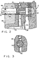
- FIG. 2 (as well as FIGS. 4 and 6) is a section taken on a different plane than the view in FIG. 1.
- FIG. 2 is taken through a section at which the cover member 17 defines a boss portion 59 which, in the subject embodiment, extends forwardly (to the left in FIG. 2) about the same distance as the cooling fins 57.
- the boss portion 59 and the main portion of the cover member 17 together define a stepped bore 61.
- Disposed adjacent the right end of the stepped bore 61 is a recess 63 defined by the input coupling member 11. It should be understood that during operation of the coupling device, the recess 63 is circumferentially aligned with the stepped bore 61, as shown in FIG. 2, only once during each rotation of the coupling member 11 relative to the cover member 17.
- a manually operable control member Disposed within the bore 61 is a manually operable control member, generally designated 65, the control member 65 including a threaded portion 67 and a cylindrical portion 69. Disposed about the cylindrical portion 69, and in sealing engagement with the bore 61 is a sealing ring 71.
- the cylindrical portion 69 also defines an opening 73 which may be configured for the insertion of a tool such as a hex-shaped Al- len wrench, to facilitate manual rotation of the control member 65 by the vehicle operator, or by a mechanic or test technician, for reasons which will be described in greater detail subsequently.
- the threaded portion 67 of the control member 65 defines an axially-extending passage 75 and a transverse passage 77.
- the cover member 17 defines a radial passage 79 which may be generally similar to the radial passage 47 shown in FIG. 1.
- the radial passage 79 intersects the stepped bore 61, and may be sealed at a location radially outward from the bore 61 by means of a pressed-in ball 81.
- the general function of the radial passage 79 is to provide a secondary fluid passage by means of which fluid may be communicated from the reservoir chamber 33 to the operating chamber 31 as will be described in greater detail subsequently.
- FIGS. 2 and 3 illustrate the "normal operation" of the fluid coupling device in which the control member 65 is rotated to the position shown such that the transverse passage 77 is blocked from fluid communication with the radial passage 79. In this position, no fluid. can flow from the reservoir chamber 33 through the radial passage 79, and into the shear space 55. Therefore, the coupling device operates in either the engaged mode or the disengaged mode, as determined solely by the "primary control means" and the manner in which it controls the flow of fluid through the "fluid passage means" in response to the predetermined temperature condition.
- the control member 65 may be rotated to the position shown in FIG. 4, in which the transverse passage 77 is aligned with, and in fluid communication with the radial passage . 79, such that there will be a continual flow of fluid from the reservoir chamber 33 radially outward through the radial passage 79, then through the transverse passage 77 and axial passage 75.
- Fluid leaving the passage 75 flows through the adjacent portion of the bore 61 and into the shear space 55. It should be apparent that it will be necessary to provide some sort of marking on the head of the control member 65 to indicate the orientation of the transverse passage 77, in order to know when looking at the front of the coupling device whether the control member 65 is in the normal operation position or in the fluid engaged position.
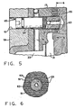
- the control member 65 may be fitted further inwardly to the position shown in FIG. 5 in which the threaded portion 67 is disposed within the recess 63. With the control member 65 in the position shown in FIGS. 5 and 6, the coupling device is now mechanically engaged, i.e., the output of the coupling is in engagement with or locked to the input, such that the cooling fan is driven at the same speed as the input shaft 21.
- control member 65 can subsequently be returned to the normal operation position shown in FIG. 2.
- FIG. 7 there is illustrated an alternative embodiment of the present invention, in which like elements bear like numerals, and new elements bear numerals in excess of 90.
- the valve plate 29 defines a greatly enlarged central opening 91 such that if the coupling device is at rest (as in FIG. 7), the fluid level in the reservoir chamber 33 will be "above” the bottom of the central opening 91, causing a substantial amount of fluid to flow from the reservoir chamber 33 into the operating chamber 31, substantially filling the shear space 55 as soon as the coupling device begins to rotate.
- the cover member 17 defines a boss portion 93, which may be generally similar to the boss portion 59 of the FIG. 2 embodiment.
- the boss portion 93 and cover member 17 define a stepped, threaded bore 95.
- the bore 95 intersects the radial passage 47 through which fluid is pumped from the operating chamber 31 back into the reservoir chamber 33.
- a manually operable control member 97 Disposed in the bore 95 is a manually operable control member 97, which includes a threaded portion 99 and a cylindrical portion 101.
- the control member 97 may be quite similar to the control member 65 of the FIG. 2 embodiment, except that the control member 97 does not define any fluid passages therethrough.
- control member 97 In the normal operation position of the FIG. 7 embodiment, the control member would be disposed such that the head of the control member 97 would be approximately flush with the front surface of the boss portion 93, and the threaded portion 99 would be disposed to permit normal discharge flow through the radial passage 47.
- the vehicle engine would be stopped for several minutes, such that the coupling device would be at rest and would have an opportunity for fluid to flow into the operating chamber 31, through the opening 91, in the manner described previously. While the engine is stopped, and the coupling device is at rest, the operator would then thread the control member 97 inwardly to the position shown in FIG. 7, blocking the radial passage 47.
- the fluid in the shear space 55 will result in torque transmission from the input coupling member 11 to the output coupling assembly 13, but because the control member 97 is now blocking the radial passage 47, the wiper 49 is unable to pump fluid out of the operating chamber 31 back into the reservoir chamber 33. Therefore, if the vehicle overheat were caused by improper calibration of the valve arm 39 and bimetal coil 43, such that the valve arm 39 would not uncover the fill opening 41 at the predetermined temperature, the manual control member 97 could be utilized to insure filling of the shear space 55 with fluid, and operation of the coupling device in the engaged condition.
- FIG. 7 has been shown only in the fluid engaged position and has been described in terms of the normal operation and fluid engaged positions. However, it would be understood by those skilled in the art that the bore 95 could be extended, and the coupling member 11 provided with a recess similar to the recess 63 in the embodiment of FIGS. 2-6, such that the control member 97 could be threaded inwardly to a position corresponding to the mechanically engaged position illustrated in FIG. 5.
- central opening 91 could be replaced by a plurality of openings spaced circumferentially around the valve plate 29, as long as the openings are positioned such that, when the coupling device is at rest, enough fluid flows from the reservoir chamber 33 to the operating chamber 31 to substantially fill the shear space 55 once the coupling device begins to rotate.
- FIG. 8 there is illustrated another alternative embodiment of the present invention in which like elements bear like numerals, and new or substantially modified elements bear numerals in excess of 110.
- the embodiment of FIG. 8 differs from the embodiments of FIGS. 2-6 and of FIG. 7 in that the manually operable control is not directly associated with a fluid passage (such as a "secondary" fill passage 79 in FIG. 4 or a "discharge” passage 47 in FIG. 7). Instead, the manual control in the FIG. 8 embodiment is operably associated with the primary control means (i.e., the valve arm 39) to control the flow of fluid in the "primary fluid passage means".
- the primary control means i.e., the valve arm 39
- the cover member 17 includes a boss portion 111 disposed on the inside of the cover member 17, and circumferentially aligned with the valve arm 39.
- the boss portion 111 defines a stepped, threaded bore 113 and disposed therein is a manually operable control member 115.
- the control member 115 includes a threaded portion 117 and a cylindrical portion 119.
- the control member 115 has a normal operation position in which the right end face of the member 115 would be approximately flush with the adjacent surface of the boss portion 111.
- FIG. 8 illustrates the fluid engaged position, in which of the manual control member 115 has been threaded inwardly to the position shown in FIG. 8 in which it engages the adjacent portion of the valve arm 39, moving that portion toward the right in FIG. 8.
- This rightward movement of that portion of the valve arm 39 causes the valve arm to pivot about a corner 121 of the stepped valve plate 29, the corner 121 acting as a fulcrum, causing the outer end of the valve arm 39 to move axially to the left in FIG. 8, uncovering the fill opening 41. Therefore, in the fluid engaged position of the manual control member 115, as shown in FIG. 8, the fill opening 41 is uncovered and the coupling device operates in the engaged mode, independently of the operation of the bimetal coil 43, and regardless of the current status of the temperature condition.
- FIG. 8 does not illustrate a specific arrangement for a mechanically engaged position.
- the valve arm 39 may be rotated, by manually turning the valve shaft 37, to a position in which the valve arm is no longer aligned with the control member 115.
- the control member 115 may then be threaded inwardly through the opening in the valve plate 29 to engage the input coupling member . 11, thus providing the mechanically engaged position.
Landscapes
- Engineering & Computer Science (AREA)
- General Engineering & Computer Science (AREA)
- Mechanical Engineering (AREA)
- Hydraulic Clutches, Magnetic Clutches, Fluid Clutches, And Fluid Joints (AREA)
- Nozzles (AREA)
Claims (10)
Applications Claiming Priority (2)
| Application Number | Priority Date | Filing Date | Title |
|---|---|---|---|
| US825507 | 1986-02-03 | ||
| US06/825,507 US4683999A (en) | 1986-02-03 | 1986-02-03 | Fluid coupling device including manual engagement means |
Publications (2)
| Publication Number | Publication Date |
|---|---|
| EP0232995A1 EP0232995A1 (de) | 1987-08-19 |
| EP0232995B1 true EP0232995B1 (de) | 1990-04-11 |
Family
ID=25244177
Family Applications (1)
| Application Number | Title | Priority Date | Filing Date |
|---|---|---|---|
| EP87300537A Expired EP0232995B1 (de) | 1986-02-03 | 1987-01-22 | Fluidkupplungseinrichtung mit handbetätigtem mechanischen Schaltmittel |
Country Status (4)
| Country | Link |
|---|---|
| US (1) | US4683999A (de) |
| EP (1) | EP0232995B1 (de) |
| JP (1) | JPS62188825A (de) |
| DE (1) | DE3762269D1 (de) |
Families Citing this family (8)
| Publication number | Priority date | Publication date | Assignee | Title |
|---|---|---|---|---|
| DE4030294A1 (de) * | 1989-09-28 | 1991-04-11 | Atsugi Unisia Corp | Fluidkupplung |
| US5022507A (en) * | 1990-07-16 | 1991-06-11 | General Motors Corporation | Anti-flowback check valve for a viscous fluid clutch |
| DE9103493U1 (de) * | 1991-03-21 | 1991-08-08 | Behr GmbH & Co, 7000 Stuttgart | Flüssigkeitsreibungskupplung |
| DE69521603T2 (de) * | 1994-03-02 | 2002-05-08 | Tl Systems Corp., Minneapolis | Füllungsvorrichtung für sterile flaschen |
| DE102004009073A1 (de) * | 2004-02-23 | 2005-09-15 | Behr Gmbh & Co. Kg | Regelbarer Antrieb für ein Kraftfahrzeug |
| DE102011016204A1 (de) * | 2011-04-06 | 2012-10-11 | Man Truck & Bus Ag | Antriebssystem der Motorkühlung für Kraftfahrzeuge |
| US9470278B1 (en) | 2015-11-10 | 2016-10-18 | Borgwarner Inc. | Apparatus employing shear forces to transmit energy having flow altering structures configured to increase heat rejection from a working fluid and related method |
| DE102018127343A1 (de) | 2017-11-06 | 2019-05-09 | Borgwarner Inc. | Schervorrichtung für ein viskoses fluid mit fest an eine gehäusebaueinheit gekoppeltem abstreifer |
Family Cites Families (9)
| Publication number | Priority date | Publication date | Assignee | Title |
|---|---|---|---|---|
| US2497893A (en) * | 1944-09-19 | 1950-02-21 | Linahan John | Synchronized and adjustable safety clutch |
| US3011607A (en) * | 1958-02-17 | 1961-12-05 | Schwitzer Corp | Fluid coupling for accessory drive |
| US3055473A (en) * | 1959-05-11 | 1962-09-25 | Eaton Mfg Co | Fluid coupling device |
| US3174600A (en) * | 1961-05-18 | 1965-03-23 | Oldberg Sidney | Temperature-responsive fluid clutch |
| NL294284A (de) * | 1962-06-20 | |||
| US3191733A (en) * | 1963-01-07 | 1965-06-29 | Schwitzer Corp | Torque transmitting fluid coupling |
| JPS5493760A (en) * | 1978-01-07 | 1979-07-25 | Toyota Motor Corp | Fluid coupling |
| US4320723A (en) * | 1979-06-11 | 1982-03-23 | Wendling Vincent F | Selectively operable fan drive arrangement |
| US4544054A (en) * | 1982-03-10 | 1985-10-01 | Eaton Corporation | Mounting shaft and adaptor for viscous coupling |
-
1986
- 1986-02-03 US US06/825,507 patent/US4683999A/en not_active Expired - Fee Related
-
1987
- 1987-01-22 DE DE8787300537T patent/DE3762269D1/de not_active Expired - Lifetime
- 1987-01-22 EP EP87300537A patent/EP0232995B1/de not_active Expired
- 1987-02-03 JP JP62023407A patent/JPS62188825A/ja active Pending
Also Published As
| Publication number | Publication date |
|---|---|
| EP0232995A1 (de) | 1987-08-19 |
| JPS62188825A (ja) | 1987-08-18 |
| US4683999A (en) | 1987-08-04 |
| DE3762269D1 (de) | 1990-05-17 |
Similar Documents
| Publication | Publication Date | Title |
|---|---|---|
| EP0009959B1 (de) | Flüssigkeitskupplung | |
| EP0015643B1 (de) | Flüssigkeitskupplung mit verbesserter Reaktionszeit | |
| US4570771A (en) | Viscous fluid coupling having centrifugal valve means | |
| US6530748B2 (en) | Enhanced fan and fan drive assembly | |
| US4544053A (en) | Temperature-responsive fluid coupling device | |
| JPH0333933B2 (de) | ||
| EP0232995B1 (de) | Fluidkupplungseinrichtung mit handbetätigtem mechanischen Schaltmittel | |
| US7044282B2 (en) | Clutchless viscous fan drive wherein input member serves as the body and the cover carries seal | |
| EP0061280B1 (de) | Regelbare Flüssigkeitsreibungskupplung | |
| US4134484A (en) | Fluid coupling | |
| US4606445A (en) | Fluid coupling device with improved fluid cooling capability | |
| US4678070A (en) | Fluid coupling device having improved heat dissipation | |
| GB2251287A (en) | Fluid friction coupling device | |
| US6896191B2 (en) | Heating device suitable for motor vehicles | |
| US4630721A (en) | Viscous clutch for engine cooling fan | |
| US4874071A (en) | Viscous clutch for engine cooling fan | |
| US4949825A (en) | Fluid coupling device having improved temperature responsiveness | |
| US4627524A (en) | Viscous fluid coupling device | |
| US5111923A (en) | Ramped clutch plate for a viscous fluid clutch | |
| EP0595073B1 (de) | Bei hohen Temperaturen ausschaltbare Flüssigkeitskupplung | |
| JPS61278626A (ja) | 流体クラツチ | |
| GB2153980A (en) | Fan coupling unit | |
| EP0201242B1 (de) | Flüssigkeitskupplungseinrichtung mit Wärmeauflösung | |
| EP0716243A1 (de) | Flüssigkeitskupplung und Wellenbefestigung dafür | |
| US5257686A (en) | Viscous fluid coupling device |
Legal Events
| Date | Code | Title | Description |
|---|---|---|---|
| PUAI | Public reference made under article 153(3) epc to a published international application that has entered the european phase |
Free format text: ORIGINAL CODE: 0009012 |
|
| AK | Designated contracting states |
Kind code of ref document: A1 Designated state(s): DE FR GB IT |
|
| 17P | Request for examination filed |
Effective date: 19880108 |
|
| 17Q | First examination report despatched |
Effective date: 19890120 |
|
| GRAA | (expected) grant |
Free format text: ORIGINAL CODE: 0009210 |
|
| AK | Designated contracting states |
Kind code of ref document: B1 Designated state(s): DE FR GB IT |
|
| ITF | It: translation for a ep patent filed | ||
| REF | Corresponds to: |
Ref document number: 3762269 Country of ref document: DE Date of ref document: 19900517 |
|
| ET | Fr: translation filed | ||
| PG25 | Lapsed in a contracting state [announced via postgrant information from national office to epo] |
Ref country code: GB Effective date: 19910122 |
|
| PLBE | No opposition filed within time limit |
Free format text: ORIGINAL CODE: 0009261 |
|
| STAA | Information on the status of an ep patent application or granted ep patent |
Free format text: STATUS: NO OPPOSITION FILED WITHIN TIME LIMIT |
|
| 26N | No opposition filed | ||
| GBPC | Gb: european patent ceased through non-payment of renewal fee | ||
| PG25 | Lapsed in a contracting state [announced via postgrant information from national office to epo] |
Ref country code: FR Effective date: 19910930 |
|
| PG25 | Lapsed in a contracting state [announced via postgrant information from national office to epo] |
Ref country code: DE Effective date: 19911001 |
|
| REG | Reference to a national code |
Ref country code: FR Ref legal event code: ST |
|
| PG25 | Lapsed in a contracting state [announced via postgrant information from national office to epo] |
Ref country code: IT Free format text: LAPSE BECAUSE OF NON-PAYMENT OF DUE FEES;WARNING: LAPSES OF ITALIAN PATENTS WITH EFFECTIVE DATE BEFORE 2007 MAY HAVE OCCURRED AT ANY TIME BEFORE 2007. THE CORRECT EFFECTIVE DATE MAY BE DIFFERENT FROM THE ONE RECORDED. Effective date: 20050122 |