EP0233143B1 - Aussenhaut von Fahrzeugen - Google Patents
Aussenhaut von Fahrzeugen Download PDFInfo
- Publication number
- EP0233143B1 EP0233143B1 EP87810042A EP87810042A EP0233143B1 EP 0233143 B1 EP0233143 B1 EP 0233143B1 EP 87810042 A EP87810042 A EP 87810042A EP 87810042 A EP87810042 A EP 87810042A EP 0233143 B1 EP0233143 B1 EP 0233143B1
- Authority
- EP
- European Patent Office
- Prior art keywords
- outer shell
- profile
- shell according
- window frame
- adjustable
- Prior art date
- Legal status (The legal status is an assumption and is not a legal conclusion. Google has not performed a legal analysis and makes no representation as to the accuracy of the status listed.)
- Expired
Links
Images


Classifications
-
- B—PERFORMING OPERATIONS; TRANSPORTING
- B61—RAILWAYS
- B61D—BODY DETAILS OR KINDS OF RAILWAY VEHICLES
- B61D25/00—Window arrangements peculiar to rail vehicles
-
- B—PERFORMING OPERATIONS; TRANSPORTING
- B32—LAYERED PRODUCTS
- B32B—LAYERED PRODUCTS, i.e. PRODUCTS BUILT-UP OF STRATA OF FLAT OR NON-FLAT, e.g. CELLULAR OR HONEYCOMB, FORM
- B32B17/00—Layered products essentially comprising sheet glass, or glass, slag, or like fibres
- B32B17/06—Layered products essentially comprising sheet glass, or glass, slag, or like fibres comprising glass as the main or only constituent of a layer, next to another layer of a specific material
- B32B17/10—Layered products essentially comprising sheet glass, or glass, slag, or like fibres comprising glass as the main or only constituent of a layer, next to another layer of a specific material of synthetic resin
- B32B17/10005—Layered products essentially comprising sheet glass, or glass, slag, or like fibres comprising glass as the main or only constituent of a layer, next to another layer of a specific material of synthetic resin laminated safety glass or glazing
- B32B17/10009—Layered products essentially comprising sheet glass, or glass, slag, or like fibres comprising glass as the main or only constituent of a layer, next to another layer of a specific material of synthetic resin laminated safety glass or glazing characterized by the number, the constitution or treatment of glass sheets
- B32B17/10036—Layered products essentially comprising sheet glass, or glass, slag, or like fibres comprising glass as the main or only constituent of a layer, next to another layer of a specific material of synthetic resin laminated safety glass or glazing characterized by the number, the constitution or treatment of glass sheets comprising two outer glass sheets
- B32B17/10045—Layered products essentially comprising sheet glass, or glass, slag, or like fibres comprising glass as the main or only constituent of a layer, next to another layer of a specific material of synthetic resin laminated safety glass or glazing characterized by the number, the constitution or treatment of glass sheets comprising two outer glass sheets with at least one intermediate layer consisting of a glass sheet
- B32B17/10055—Layered products essentially comprising sheet glass, or glass, slag, or like fibres comprising glass as the main or only constituent of a layer, next to another layer of a specific material of synthetic resin laminated safety glass or glazing characterized by the number, the constitution or treatment of glass sheets comprising two outer glass sheets with at least one intermediate layer consisting of a glass sheet with at least one intermediate air space
-
- B—PERFORMING OPERATIONS; TRANSPORTING
- B60—VEHICLES IN GENERAL
- B60J—WINDOWS, WINDSCREENS, NON-FIXED ROOFS, DOORS, OR SIMILAR DEVICES FOR VEHICLES; REMOVABLE EXTERNAL PROTECTIVE COVERINGS SPECIALLY ADAPTED FOR VEHICLES
- B60J1/00—Windows; Windscreens; Accessories therefor
- B60J1/08—Windows; Windscreens; Accessories therefor arranged at vehicle sides
- B60J1/10—Windows; Windscreens; Accessories therefor arranged at vehicle sides fixedly mounted
Definitions
- the invention relates to an outer skin of vehicles, in particular for the transportation of people by rail and road, with precisely aligned adjustable window glazing, which is held by means of window frame profiles detachably attached to the side wall or post profiles.
- DE-A 3 117 103 deals with the formation of the edging of the windows of vehicles, in particular those of rail-bound traffic.
- the window surrounds are flush with the respective window of the outer skin of the vehicle, the surround frame engaging over the vehicle-internal pane of the outside laminated glazing.
- This disc is dimensioned smaller than the inner disc. Together with the seal, which is also flush with the outer skin, this brings about an improvement in aerodynamic resistance, a simplification of the washing process and a reduction in noise during fast driving.
- the aim is to improve the flushness of the outer skin of the insulating glass windows by substantially simplifying the individual assembly of the window frame in the window cutout of the vehicle structure that is necessary to compensate for manufacturing tolerances.
- the vehicle structure in the region of the window cutout is designed as a hollow profile slotted on the vehicle interior, and the fastening means can be positioned behind the hollow profile slot so as to be displaceable on the hollow profile in the longitudinal direction of the slot.
- Compensating means inserted between the hollow profile of the vehicle structure and the profile leg of the window frame profile and clamped when the screws are tightened allow the outer pane to be exactly aligned with the outer skin of the vehicle when installed.
- the last-mentioned publication allows the flushness of the outer pane of the glazing to be adjusted in the direction perpendicular to the outer skin.
- this is extremely tedious, since numerous thicknesses of shims must be kept in stock. After assembly, the flushness of the outer pane can only be corrected if all screw connections are opened and the compensating means are replaced.
- the inventor has therefore set himself the task of creating an outer skin of vehicles with precisely aligned adjustable window glazing, wherein manufacturing tolerances can also be easily compensated for at any time even in the direction running vertically to the outer skin.
- the object is achieved according to the invention by means of means for anchoring the window frame profiles on the side wall or post profiles, which means are adjustable in length by means of a rotary movement, which means are mounted against rotation after the adjustment.
- the invention not only ensures simple, quick assembly with modest aids, but also ensures that the flushness of the outer pane or parts thereof can be adjusted at any time without dismantling work, previously only a cover must be removed or a lock nut loosened.
- the adjustable means for anchoring the window frame profiles are usually mounted with the positioning part facing outwards. If this is made exclusively of metallic parts, a cold bridge can arise, which must be carefully covered on the inside. For this reason, screw heads are preferably used, which consist of a steel sleeve which is encased in a hard plastic. In this case, the washer of the corresponding tightening nut is also made of a hard plastic.
- the hard plastic parts mentioned suitably consist of polyethylene, polypropylene or a polyamide. Other plastic materials that are also suitable per se, such as Polyvinyl chloride, are used less today because of their environmentally harmful character.
- the face of the threaded pin pointing away from the screw head, in case it has to be rotated in order to adjust the flushness of the outer washer, has in practice a cutout or molding for the positive reception of a tool.
- All known shapes are suitable, for example a slot for a screwdriver, a hexagonal blind hole for an Allen key or a square or hexagonal recess in the circumference for attaching a fork wrench.
- the adjustment sleeve can also be rotated for the aforementioned adjustment by means of a tool which engages at correspondingly shaped points.
- the window frame profile can be installed from the inside or outside.
- the screw head of the positioning part of the adjustable means is tightened in an undercut longitudinal groove of a side wall or post profile with a longitudinal slot pointing in the direction of the vehicle interior, in the second case in a correspondingly designed longitudinal groove of the window frame profile.
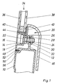
- the extruded side wall profile 10 made of a suitable aluminum alloy has, in the uppermost region, offset inwards, a profile flag 12 arranged in the vertical direction.
- a window frame profile 14 has a longitudinally extending, undercut longitudinal groove 16 in cross-section, into which laterally several screw heads 18 from adjustable means are introduced. These are distributed over the entire length of the window frame profile 14.
- Integrally formed on the screw head 18 is a locking device 22, which is inserted into the longitudinal slot of the undercut groove 16 pointing in the direction of the vehicle interior.
- a plastic washer 26 is first pushed onto the threaded pin 24, which is also formed integrally with the screw head 18, whereupon a tightening nut 28 is screwed on and tightened. As a result, the threaded pin 24 is firmly positioned.
- the window frame profile is inserted via the threaded pin 24 into a hole or an elongated hole of the profile flag 12 running in the longitudinal direction of the side wall profile 10. While one screw nut 30 is already screwed on before the threaded pin 24 is inserted, the other screw nut 32 is screwed on afterwards. In the present case, the two screw nuts 30 and 32, together with the end of the threaded pin 24 remote from the screw head 18, form the length-adjustable part of the ascertainable means. The two nuts can be tightened in a precisely adjustable position and the window frame profile 14 can thus be anchored to the side wall profile 10.
- the window glazing 34 of a known type comprises an outer composite pane 36 and an inner simple pane 38. A spacer 40 is at the same time a support frame, spacer and sealing of the cavity lying between the composite pane 36 and the inner pane 38. The window glazing 34 is fitted into an L-shaped stop 42, which is lined with a layer of adhesive 44.
- An inner cover plate 46 leads from the inner disc 38, initially curved in an arc, and then adjoins the inner side profile wall. This means that a screw head 18, which may not be insulated, cannot form a cold bridge.
- the firmly anchored window glazing can be adjusted exactly flush to the outer skin by tightening the screw nuts 30, 32 in the appropriate position. If the position of the window glazing has to be adjusted vertically to the laminated pane over the course of time, this can be done easily and without expensive disassembly work by loosening the screw nuts 30, 32 after changing the cover plate 46, slightly changing their position and then tightening them again.
- the window frame profile 14 consists of an injection molded plastic profile. Since a cold bridge cannot form under any circumstances, the screw head 18 is of purely metallic design for cost reasons.
- the side wall profile 10 is extruded such that the foot 48 of the window frame profile 14 can be supported indirectly on the shoulder 50 of the side wall profile 10.
- Adhesive 52 is applied between these two parts and seals the joint between window frame profile 14 and side wall profile 10 after drying.
- a horizontal groove running in the longitudinal direction in the area of the shoulder 50 of the side wall profile 10 is filled with foam 56, which extends over the horizontal area of the side wall profile up to the profile flag 12 and thus offers protection against structure-borne noise transmission in the connection area.
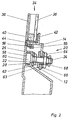
- the side wall profile 10 has an undercut longitudinal groove 58 in its uppermost region, into which a plurality of screw heads 60 by adjustable means 20 are inserted laterally.
- the anti-rotation device 22 inserted into the longitudinal slot of the groove can be seen from the inserted screw head 60.
- An insulating screw head 60 is necessary here, otherwise a cold bridge would be formed.
- the tightening nut 28 acts via the plastic washer 26 on the screw head 60, which is drawn against the longitudinal slot of the horizontal groove 58, which is C-shaped in cross section, and is thus positioned.
- An adjusting bush 62 is screwed onto the threaded pin 24, which can be freely rotated in the screw head, and which can be fixed in any position by means of a tightening nut 64, which acts on a washer 66.
- the window frame profile 14 which in the present case is made of aluminum, is fastened via a molded profile lug 12 by the tightening nut 64 clamping the adjustment lug 62 through a base or elongated hole through its base plate 63.
- the end face of the adjusting bush 62 which is provided with a slot and points in the direction of the interior of the carriage can be displaced in the longitudinal direction of the threaded pin 24 using a screwdriver or a similar tool.
- the adjusting sleeve 62 is fixed with a lock nut 68.
- the space between the adhesive layer 44 and the L-shaped extension 55 is filled with foam 56.
- the lock nut 68 can be loosened or removed and the tightening nut 64 loosened. Now the adjusting sleeve 62 can be rotated, which results in a precisely adjustable change in distance. Then the two nuts are tightened again.
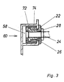
- a positioning part with an insulated screw head 60 is shown in detail in FIG. 3.
- the undercut longitudinal groove 58 of the side wall profile 10 receives the screw head 60, which consists of a steel sleeve 72 and an insulating coating 74 made of polyethylene.
- the anti-rotation device 22 is inserted into the longitudinal slot of the undercut C-shaped longitudinal groove 58.
- the set screw 24 is freely rotatable before tightening the tightening nut 28, which acts on the washer 26.
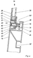
- the post profile 76 shown in FIG. 4 has an undercut longitudinal groove 78 running on the inside of the carriage for fastening the adjustable means 20 by means of a screw head 18.
- a profile lug 12 of the window frame profile 14 is penetrated by an adjusting bush 62.
- an Allen key is inserted into the blind hole, which is hexagonal in cross section, in the adjusting bush 62 and is rotated in the corresponding sense.
- the set screw 24 ends in a blind axial bore of the adjusting bush 62.
- the tightening nut 64 acts on the profile lug 12 via a washer 66, to which the base plate 63 of the adjusting bush 62 is pulled from the other side. This is fixed with a lock nut 68.
- the adjusting sleeve 62 is designed to be insulating, analogous to the screw head 60 shown in FIG. 3.
- the positioning part with the screw head 18 is designed as in the previous figures.
- Another undercut longitudinal profile 82 is used to fasten other structural parts.
- FIG. 5 shows the fixing of an aperture 84, which has the tone of a glass pane, by means of an adhesive 44.
- the representation of the adjustable means 20 has been dispensed with; these are - like the other construction parts - designed according to a previously illustrated embodiment.
- An insulating washer 34 with outer insulating 36 and inner glazing 38 is fastened by means of an adhesive 44 to a window frame profile 14, which in turn is fixed in an adjustable manner to the profile lug 12 of the side wall profile 10.
- FIG. 6 a variant of FIG. 1, a normal screw consisting of a hexagon screw head 18 and a set screw 24 is inserted from the inside through a bore in the profile lug 12 of the side wall profile 10 and fixed with a lock nut 68, whereby the positioning part is fixed .
- the set screw 24 is screwed into an insulating adjusting sleeve 62 (FIG. 3) which is fixed in the undercut longitudinal groove 16 by means of an anti-rotation device 22.
- the composite pane 36 of the window glazing 34 is arranged on the inside.
- the simple outer pane 86 is flush with the outer skin of the vehicle.
- FIG. 7 differs only by a sealing lip 88 arranged in an undercut longitudinal groove, which replaces the adhesive 52 from FIG. 6 and fills the longitudinal joint between the foot 48, the window frame profile 14 and the side wall profile 10 .
- the shoulder 50 of the side wall profile 10 is designed accordingly.
Landscapes
- Engineering & Computer Science (AREA)
- Mechanical Engineering (AREA)
- Window Of Vehicle (AREA)
- Outer Garments And Coats (AREA)
- Structure Of Belt Conveyors (AREA)
- Physical Deposition Of Substances That Are Components Of Semiconductor Devices (AREA)
- Paints Or Removers (AREA)
- Body Structure For Vehicles (AREA)
- Road Paving Structures (AREA)
- Seal Device For Vehicle (AREA)
- Escalators And Moving Walkways (AREA)
Description
- Die Erfindung bezieht sich auf eine Aussenhaut von Fahrzeugen, insbesondere zur Beförderung von Personen auf Schiene und Strasse, mit genau fluchtend einstellbarer Fensterverglasung, welche mittels an den Seitenwand- bzw. den Pfostenprofilen lösbar befestigter Fensterrahmenprofile gehaltert ist.
- Die DE-A 3 117 103 hat die Ausbildung der Einfassungen der Fenster von Fahrzeugen, insbesondere solchen des schienengebundenen Verkehrs, zum Gegenstand. Dabei sind die Fenstereinfassungen mit dem jeweiligen Fenster der Aussenhaut des Fahrzeuges bündig, wobei der Einfassrahmen die fahrzeuginnere Scheibe der aussenseitigen Verbundglasung übergreift. Diese Scheibe ist entsprechend kleiner bemessen als die innere Scheibe. Dies bringt - zusammen mit der ebenfalls aussenhautbündigen Dichtung - eine Verbesserung des aerodynamischen Widerstands, eine Vereinfachung des Waschvorgangs und eine Verminderung von Geräuschen bei schneller Fahrt.
- In der DE-A 3 344 180 wird angestrebt, die Aussenhautbündigkeit der Isolierglasfenster zu verbessern, indem die zum Ausgleich von Fertigungstoleranzen erforderliche, individuelle Montage des Fensterrahmens im Fensterausschnitt der Fahrzeugstruktur wesentlich vereinfacht wird. Dies wird dadurch erreicht, dass die Fahrzeugstruktur im Bereich des Fensterausschnitts als fahrzeuginnenseitig geschlitztes Hohlprofil ausgebildet ist, und die Befestigungsmittel jeweils den Hohlprofilschlitz hintergreifend in Schlitzlängsrichtung verschieblich am Hohlprofil positionierbar sind.
- Zwischen dem Hohlprofil der Fahrzeugstruktur und dem Profilschenkel des Fensterrahmenprofils eingelegte und beim Festziehen der Schrauben festgeklemmte Ausgleichsmittel erlauben, dass die Aussenscheibe im eingebauten Zustand exakt fluchtend zur Fahrzeugaussenhaut ausgerichtet ist.
- Die letztgenannte Druckschrift erlaubt im Gegensatz zur vorhergehenden, dass die Bündigkeit der Aussenscheibe der Verglasung in zur Aussenhaut senkrechter Richtung eingestellt werden kann. Dies ist jedoch ausserordentlich mühsam, müssen doch zahlreiche Dicken von Ausgleichsscheiben am Lager gehalten werden. Weiter kann nach der Montage die Bündigkeit der Aussenscheibe nur korrigiert werden, wenn alle Verschraubungen geöffnet und die Ausgleichsmittel ausgewechselt werden.
- Der Erfinder hat sich deshalb die Aufgabe gestellt, eine Aussenhaut von Fahrzeugen mit genau fluchtend einstellbarer Fensterverglasung zu schaffen, wobei Fertigungstoleranzen auch in vertikal zur Aussenhaut verlaufender Richtung jederzeit problemlos ausgeglichen werden können.
- Die Aufgabe wird erfindungsgemäss gelöst durch mit einer Drehbewegung in der Länge verstellbare Mittel zum Verankern der Fensterrahmenprofile an den Seitenwand- bzw. Pfostenprofilen, welche Mittel nach dem Einstellen verdrehsicher montiert sind.
- Die Erfindung gewährleistet nicht nur eine einfache, schnelle Montage mit bescheidenen Hilfsmitteln, sondern stellt weiter sicher, dass die Bündigkeit der Aussenscheibe oder Teilen davon jederzeit ohne Demontagearbeit justierbar ist, vorgängig muss höchstens eine Abdeckung entfernt bzw. eine Kontermutter gelöst werden.
- Die verstellbaren Mittel zum Verankern der Fensterrahmenprofile an der durch die Seitenwand-und die Pfostenprofile gebildeten Wagenstruktur bestehen im Prinzip aus drei Teilen:
- - Einem Gewindestift,
- - einem Positionierungsteil, welcher aus einem Schraubenkopf mit einer Verdrehsicherung und einer durchgehenden Bohrung zur Aufnahme des Gewindestifts und einer Festziehmutter mit Unterlagscheibe besteht, und
- - einem in bezug auf den Gewindestift längenverstellbaren Teil, welcher nach einer ersten Variante aus zwei Schraubenmuttern, nach einer zweiten Variante aus einer nicht in das Gewinde des Gewindestifts eingreifenden Verstellbüchse, einer Festziehmutter mit Unterlagscheibe und einer Kontermutter besteht.
- Die verstellbaren Mittel zum Verankern der Fensterrahmenprofile werden meist mit dem Positionierungsteil nach aussen montiert. Falls dieser ausschliesslich aus metallischen Teilen ausgebildet ist, kann eine Kältebrücke entstehen, welche nach innen sorgfältig abgedeckt werden muss. Deshalb werden vorzugsweise Schraubenköpfe eingesetzt, welche aus einer Stahlbüchse bestehen, die mit einem Hartkunststoff umhüllt ist. In diesem Fall besteht die Unterlagscheibe der entsprechenden Festziehmutter ebenfalls aus einem Hartkunststoff. Zweckmässig bestehen die erwähnten Hartkunststoffteile aus Polyäthylen, Polypropylen oder einem Polyamid. Andere, an sich ebenfalls geeignete Kunststoffwerkstoffe, wie z.B. Polyvinylchlorid, werden heute wegen ihres umweltbelastenden Charakters weniger eingesetzt.
- Die vom Schraubenkopf wegweisende Stirnseite des Gewindestifts weist, falls dieser zur Justierung der Bündigkeit der Aussenscheibe gedreht werden muss, in der Praxis eine Aussparung bzw. Anformung zur formschlüssigen Aufnahme eines Werkzeugs auf. Dabei sind alle bekannten Formen geeignet, beispielsweise ein Schlitz für einen Schraubenzieher, ein Sechskant-Sackloch für einen Imbusschlüssel oder eine vier- bzw. sechseckige Aussparung des Umfangs zum Ansetzen eines Gabelschlüssels.
- Anstelle des Gewindestifts, welcher auch mit dem Schraubenkopf verbunden oder mit diesem einstückig ausgebildet sein kann, kann zur erwähnten Justierung auch die Verstellbüchse mittels eines an entsprechend ausgeformten Stellen angreifenden Werkzeugs gedreht werden.
- Der Einbau des Fensterrahmenprofils kann von innen oder von aussen erfolgen. Im ersten Fall wird der Schraubenkopf des Positionierungsteils der verstellbaren Mittel in einer hinterschnittenen Längsnut eines Seitenwand- bzw. Pfostenprofils mit in Richtung des Fahrzeuginnern weisendem Längsschlitz festgezogen, im zweiten Fall in einer entsprechend ausgebildeten Längsnut des Fensterrahmenprofils.
- Die Erfindung wird anhand von in der Zeichnung dargestellten Ausführungsbeispielen näher erläutert. Es zeigen schematisch:
- - Fig. 1 einen vertikalen Teilschnitt durch den Uebergangsbereich Seitenwandprofil-Fensterverglasung, wobei der Einbau des Fensterrahmenprofils von aussen erfolgt,
- - Fig. 2 einen vertikalen Teilschnitt durch den Uebergangsbereich Seitenwandprofil-Fensterverglasung, wobei das Fensterrahmenprofil von innen eingebaut wird,
- - Fig. 3 einen vergrösserten Vertikalschnitt von Fig. 2 durch den Positionierungsteil,
- - Fig. 4 einen horizontalen Teilschnitt im Bereich des Uebergangs von einem Pfostenprofil zur Fensterverglasung,
- - Fig. 5 eine Variante von Fig. 4,
- - Fig. 6 eine Variante von Fig. 1, und
- - Fig. 7 eine Variante von Fig. 6.
- Das stranggepresste Seitenwandprofil 10 aus einer geeigneten Aluminiumlegierung hat im obersten Bereich, nach innen versetzt, eine in vertikaler Richtung angeordnete Profilfahne 12. Ein Fensterrahmenprofil 14 hat eine in Längsrichtung verlaufende, im Querschnitt C-förmige hinterschnittene Längsnut 16, in welche seitlich mehrere Schraubenköpfe 18 von verstellbaren Mitteln eingeführt werden. Diese werden über die ganze Länge des Fensterrahmenprofils 14 verteilt. Einstückig an den Schraubenkopf 18 angeformt ist eine Ver drehsicherung 22, welche in den in Richtung des Fahrzeuginnern weisenden Längsschlitz der hinterschnittenen Nut 16 eingeführt ist. Auf den ebenfalls einstückig mit dem Schraubenkopf 18 ausgebildeten Gewindestift 24 wird vorerst eine Unterlagscheibe 26 aus Kunststoff eingeschoben, worauf eine Festziehmutter 28 aufgeschraubt und angezogen wird. Dadurch wird der Gewindestift 24 fest positioniert.
- Das Fensterrahmenprofil wird über den Gewindestift 24 in ein Loch bzw. ein in Längsrichtung des Seitenwandprofils 10 verlaufendes Langloch der Profilfahne 12 eingeführt. Während die eine Schraubenmutter 30 bereits vor dem Einführen des Gewindestifts 24 aufgeschraubt ist, wird die andere Schraubenmutter 32 nachher aufgeschraubt. Die beiden Schraubenmuttern 30 und 32 bilden im vorliegenden Fall, zusammen mit dem dem Schraubenkopf 18 fernen Ende des Gewindestifts 24 den längenverstellbaren Teil der feststellbaren Mittel. Die beiden Schraubenmuttern können in exakt einstellbarer Lage angezogen und so das Fensterrahmenprofil 14 am Seitenwandprofil 10 verankert werden. Die Fensterverglasung 34 bekannter Bauart umfasst eine äussere Verbundscheibe 36 und eine innere einfache Scheibe 38. Ein Abstandstück 40 ist zugleich Stützrahmen, Distanzhalter und Versiegelung des zwischen der Verbundscheibe 36 und der inneren Scheibe 38 liegenden Hohlraums. Die Fensterverglasung 34 wird in einen L-förmigen Anschlag 42, welcher mit einer Schicht Klebstoff 44 ausgelegt ist, eingepasst.
- Von der inneren Scheibe 38 führt, vorerst bogenförmig geschwungen, eine innere Abdeckungsplatte 46 nach unten und schliesst sich dann an die innere Seitenprofilwand an. Damit kann ein gegebenenfalls nicht isolierter Schraubenkopf 18 keine Kältebrücke bilden.
- Die fest verankerte Fensterverglasung kann exakt bündig an die Aussenhaut angepasst werden, indem die Schraubenmuttern 30, 32 in entsprechender Lage angezogen werden. Muss nun die Position der Fensterverglasung im Laufe der Zeit vertikal zur Verbundscheibe justiert werden, kann dies problemlos und ohne aufwendige Demontagearbeiten erfolgen, indem nach dem Entfernen der Abdeckungsplatte 46 die Schraubenmuttern 30, 32 gelöst, ihre Position leicht verändert und dann wieder angezogen werden.
- Im Beispiel von Fig. 1 besteht das Fensterrahmenprofil 14 aus einem gespritzten Kunststoffprofil. Da sich auf keinen Fall eine Kältebrücke bilden kann, ist der Schraubenkopf 18 aus Kostengründen rein metallisch ausgebildet.
- Das Seitenwandprofil 10 ist so stranggepresst, dass sich der Fuss 48 des Fensterrahmenprofils 14 indirekt auf der Schulter 50 des Seitenwandprofils 10 abstützen kann. Zwischen diesen beiden Teilen ist Klebstoff 52 aufgetragen, welcher nach dem Trocknen die Fuge zwischen Fensterrahmenprofil 14 und Seitenwandprofil 10 abdichtet. Eine im Bereich der Schulter 50 des Seitenwandprofils 10 in Längsrichtung verlaufende Horizontalnut ist mit Schaumstoff 56 gefüllt, welcher sich über dem horizontalen Bereich des Seitenwandprofils bis zur Profilfahne 12 erstreckt und so im Verbindungsbereich einen Schutz gegen Körperschallübertragung bietet.
- In der Ausführungsform nach Fig. 2 hat das Seitenwandprofil 10 in dessen oberstem Bereich eine hinterschnittene Längsnut 58, in welche seitlich mehrere Schraubenköpfe 60 von verstellbaren Mitteln 20 eingeführt werden. Anhand des eingeführten Schraubenkopfs 60 ist die in den Längsschlitz der Nut eingeführte Verdrehsicherung 22 erkennbar. Ein isolierender Schraubenkopf 60 ist hier notwendig, weil sonst eine Kältebrücke gebildet würde. Die Festziehmutter 28 wirkt über die Unterlagscheibe 26 aus Kunststoff auf den Schraubenkopf 60 ein, welcher gegen den Längsschlitz der im Querschnitt C-förmigen Horizontalnut 58 gezogen und so positioniert wird. Auf den im Schraubenkopf frei drehbaren Gewindestift 24 ist eine Verstellbüchse 62 aufgeschraubt, welche in jeder beliebigen Lage mittels einer Festziehmutter 64, die auf eine Unterlagscheibe 66 einwirkt, fixiert werden kann.
- Das im vorliegenden Fall aus Aluminium bestehende Fensterrahmenprofil 14 wird über eine angeformte Profilfahne 12 befestigt, indem die Festziehmutter 64 die die erwähnte Profilfahne 12 in einem Loch bzw. Langloch durchgreifende Verstellbüchse 62 über ihre Basisplatte 63 festklemmt.
- Die mit einem Schlitz versehene, in Richtung des Wageninnern weisende Stirnfläche der Verstellbüchse 62 kann mit einem Schraubenzieher oder einem ähnlichen Werkzeug durch Drehen in Längsrichtung des Gewindestifts 24 verschoben werden. Wenn ihre endgültige Lage festgelegt ist, wird die Verstellbüchse 62 mit einer Kontermutter 68 fixiert.
- Die Fensterverglasung 34 mit der äusseren Verbundscheibe 36 und der inneren einfachen Scheibe 38, zusammengehalten vom Abstandstück 40, wird in den mit einer Klebstoffschicht 44 ausgelegten Anschlag 42 eingefügt. Der Raum zwischen der Klebstoffschicht 44 und dem L-förmigen Ansatz 55 ist mit Schaumstoff 56 gefüllt.
- Muss gemäss Fig. 2 die Bündigkeit von äusserer Verbundscheibe 36 und der äusseren Oberfläche des Seitenwandprofils 10 neu eingestellt werden, kann die Kontermutter 68 gelöst bzw. entfernt und die Festziehmutter 64 gelöst werden. Nun kann die Verstellbüchse 62 gedreht werden, was eine genau einstellbare Abstandsveränderung zur Folge hat. Dann werden die beiden Muttern wieder angezogen bzw. aufgesetzt.
- In Fig. 3 ist ein Positionierungsteil mit isoliertem Schraubenkopf 60 im Detail dargestellt. Die hinterschnittene Längsnut 58 des Seitenwandprofils 10 nimmt den Schraubenkopf 60 auf, welcher aus einer Stahlbüchse 72 und einem isolierenden Ueberzug 74 aus Polyäthylen besteht. Die Verdrehsicherung 22 ist in den Längsschlitz der hinterschnittenen C-förmigen Längsnut 58 eingeführt. Der Gewindestift 24 ist vor dem Anziehen der Festziehmutter 28, welche über die Unterlagscheibe 26 einwirkt, frei drehbar.
- Das in Fig. 4 dargestellte Pfostenprofil 76 hat zur Befestigung der verstellbaren Mittel 20 mittels eines Schraubenkopfs 18 eine auf der Wageninnenseite verlaufende hinterschnittene Längsnut 78. Analog zur Fig. 2 wird eine Profilfahne 12 des Fensterrahmenprofils 14 von einer Verstellbüchse 62 durchgriffen. Beim Einstellen der Bündigkeit der äusseren Verbundscheibe 36 wird ein Imbusschlüssei in das im Querschnitt sechseckige Sackloch in der Verstellbüchse 62 gesteckt und diese im entsprechenden Sinne gedreht. Der Gewindestift 24 endet in einer blinden Axialbohrung der Verstellbüchse 62. Die Festziehmutter 64 wirkt über eine Unterlagscheibe 66 auf die Profilfahne 12 ein, an welche von der andem Seite die Basisplatte 63 der Verstellbüchse 62 gezogen wird. Diese wird mit einer Kontermutter 68 fixiert. Die Verstellbüchse 62 ist analog zum in Fig. 3 dargestellten Schraubenkopf 60 isolierend ausgebildet.
- Der Positionierungsteil mit dem Schraubenkopf 18 ist wie in den vorhergehenden Figuren ausgebildet.
- Ein weiteres hinterschnittenes Längsprofil 82 dient der Befestigung von anderen Konstruktionsteilen.
- In Fig. 5 ist die Festlegung einer Blende 84, welche den Ton einer Glasscheibe hat, mittels eines Klebstoffs 44 gezeigt. Einfachheitshalber ist auf die Darstellung der verstellbaren Mittel 20 verzichtet worden, diese sind - wie die übrigen Konstruktionsteile - nach einer vorher dargestellten Ausführungsform konzipiert. Eine Isolierscheibe 34 mit äusserer Isolier- 36 und innerer Verglasung 38 ist mittels eines Klebstoffs 44 an einem Fensterrahmenprofil 14 befestigt, das seinerseits einstellbar an der Profilfahne 12 des Seitenwandprofils 10 fixiert ist.
- Nach Fig. 6, einer Variante von Fig. 1, ist eine normale Schraube aus einem Sechskant-Schraubenkopf 18 und einem Gewindestift 24 von innen durch eine Bohrung der Profilfahne 12 des Seitenwandprofils 10 gesteckt und mit einer Kontermutter 68 fixiert, wodurch der Positionierungsteil festgelegt ist. Der Gewindestift 24 ist in eine in der hinterschnittenen Längsnut 16 mittels einer Verdrehsicherung 22 festgelegte, isolierende Verstellbüchse 62 (Fig. 3) geschraubt. Diese Elemente bilden, zusammen mit der Festzieh mutter 28, den längenverstellbaren Teil der verstellbaren Mittel 20.
- Unterschiedlich zu Fig. 1 ist die Verbundscheibe 36 der Fensterverglasung 34 auf der Innenseite angeordnet. Die einfache Aussenscheibe 86 ist mit der Aussenhaut des Fahrzeugs bündig.
- Im Vergleich zu Fig. 6 unterscheidet sich Fig. 7 nur durch eine in einer hinterschnittenen Längsnut angeordnete Dichtlippe 88, welche den Klebstoff 52 von Fig. 6 ersetzt und die in Längsrichtung verlaufende Fuge zwischen dem Fuss 48, dem Fensterrahmenpropfil 14 und dem Seitenwandprofil 10 füllt. Die Schulter 50 des Seitenwandprofils 10 ist entsprechend ausgebildet.
Claims (10)
Applications Claiming Priority (2)
| Application Number | Priority Date | Filing Date | Title |
|---|---|---|---|
| CH442/86 | 1986-02-05 | ||
| CH44286 | 1986-02-05 |
Publications (3)
| Publication Number | Publication Date |
|---|---|
| EP0233143A1 EP0233143A1 (de) | 1987-08-19 |
| EP0233143B1 true EP0233143B1 (de) | 1989-09-13 |
| EP0233143B2 EP0233143B2 (de) | 1995-09-06 |
Family
ID=4187122
Family Applications (1)
| Application Number | Title | Priority Date | Filing Date |
|---|---|---|---|
| EP87810042A Expired - Lifetime EP0233143B2 (de) | 1986-02-05 | 1987-01-23 | Aussenhaut von Fahrzeugen |
Country Status (6)
| Country | Link |
|---|---|
| EP (1) | EP0233143B2 (de) |
| AT (1) | ATE46294T1 (de) |
| DE (1) | DE3760551D1 (de) |
| DK (1) | DK161504C (de) |
| ES (1) | ES2011301T5 (de) |
| NO (1) | NO165181C (de) |
Cited By (1)
| Publication number | Priority date | Publication date | Assignee | Title |
|---|---|---|---|---|
| DE4005091A1 (de) * | 1990-02-17 | 1991-08-22 | Daimler Benz Ag | Einricht- und feststellvorrichtung fuer eine fensterverglasung eines fahrzeugs |
Families Citing this family (11)
| Publication number | Priority date | Publication date | Assignee | Title |
|---|---|---|---|---|
| FR2627224A1 (fr) * | 1988-02-15 | 1989-08-18 | Pommier & Cie | Dispositif de garnissage pour baies vitrees de vehicules et applications analogues |
| WO1990001940A1 (en) * | 1988-08-18 | 1990-03-08 | California Biotechnology Inc. | Atrial natriuretic peptide clearance inhibitors |
| FR2679592A1 (fr) * | 1991-07-12 | 1993-01-29 | Klein Ets Georges | Vitrage, notamment pour fenetre de vehicule ferroviaire ou routier. |
| EP0609646A1 (de) * | 1992-12-29 | 1994-08-10 | Wiener Metallwerk Gmbh | Fenster in einer Aussenwand |
| FR2742099B1 (fr) † | 1995-12-08 | 1998-01-02 | Farnier & Penin | Dispositif de fermeture affleurant d'une baie de vehicule automobile |
| DE10043026B4 (de) * | 2000-09-01 | 2004-07-01 | Audi Ag | Gepanzertes Fahrzeug |
| SE518161C2 (sv) * | 2001-01-26 | 2002-09-03 | Bombardier Transp Gmbh | Ett fixerat fönster och ett sätt att fixera ett fönster |
| FR3005022B1 (fr) * | 2013-04-24 | 2016-12-23 | Alstom Transp Tech | Assemblage de plaque, voiture de vehicule ferroviaire et procede de montage associes |
| DE102015214484A1 (de) * | 2015-07-30 | 2017-02-02 | Siemens Aktiengesellschaft | Isolierglaselement sowie Fahrzeug mit Isolierglaselement |
| DE102016116395A1 (de) | 2016-09-01 | 2018-03-01 | Dr. Ing. H.C. F. Porsche Aktiengesellschaft | Tür zur Befestigung an einem Kraftfahrzeug |
| RU2718871C2 (ru) | 2016-11-03 | 2020-04-15 | СиАрАрСи ЦИНДАО СЫФАН КО., ЛТД. | Конструкция окна поезда и поезд с такой конструкцией окна |
Family Cites Families (3)
| Publication number | Priority date | Publication date | Assignee | Title |
|---|---|---|---|---|
| CH466906A (de) * | 1968-04-11 | 1968-12-31 | Otto Gamma Ag | Einrichtung zum Befestigen von plattenförmigen Bauteilen |
| DE8301436U1 (de) * | 1983-01-20 | 1988-09-15 | Messerschmitt-Boelkow-Blohm Gmbh, 8012 Ottobrunn, De | |
| DE3323238A1 (de) * | 1983-01-20 | 1985-01-10 | Messerschmitt-Bölkow-Blohm GmbH, 8012 Ottobrunn | Isolierglasfenster |
-
1987
- 1987-01-23 EP EP87810042A patent/EP0233143B2/de not_active Expired - Lifetime
- 1987-01-23 ES ES87810042T patent/ES2011301T5/es not_active Expired - Lifetime
- 1987-01-23 AT AT87810042T patent/ATE46294T1/de not_active IP Right Cessation
- 1987-01-23 DE DE8787810042T patent/DE3760551D1/de not_active Expired
- 1987-02-03 DK DK054587A patent/DK161504C/da not_active IP Right Cessation
- 1987-02-03 NO NO870427A patent/NO165181C/no unknown
Cited By (1)
| Publication number | Priority date | Publication date | Assignee | Title |
|---|---|---|---|---|
| DE4005091A1 (de) * | 1990-02-17 | 1991-08-22 | Daimler Benz Ag | Einricht- und feststellvorrichtung fuer eine fensterverglasung eines fahrzeugs |
Also Published As
| Publication number | Publication date |
|---|---|
| EP0233143A1 (de) | 1987-08-19 |
| DK161504B (da) | 1991-07-15 |
| DE3760551D1 (en) | 1989-10-19 |
| NO165181B (no) | 1990-10-01 |
| EP0233143B2 (de) | 1995-09-06 |
| ES2011301T5 (es) | 1996-01-16 |
| DK54587A (da) | 1987-08-06 |
| DK54587D0 (da) | 1987-02-03 |
| ES2011301B3 (es) | 1990-01-01 |
| ATE46294T1 (de) | 1989-09-15 |
| NO870427L (no) | 1987-08-06 |
| NO870427D0 (no) | 1987-02-03 |
| DK161504C (da) | 1992-01-13 |
| NO165181C (no) | 1991-01-09 |
Similar Documents
| Publication | Publication Date | Title |
|---|---|---|
| DE69600180T2 (de) | Befestigungselement mit schraubengewinde | |
| EP0233143B1 (de) | Aussenhaut von Fahrzeugen | |
| DE2240858A1 (de) | Fahrzeugtueren | |
| EP1090830B1 (de) | Baugruppenverbindung | |
| DE3502175A1 (de) | Verstellvorrichtung an einem waehrend und nach der montage verstellbaren tuer- und fensterband | |
| DE4342097A1 (de) | Halterung für die biegemomentfreie Lagerung von Glasplatten | |
| DE3344180C2 (de) | ||
| EP2108545B1 (de) | Anordnung zur Befestigung eines Profils, insbesondere eines Hohlprofils, an einem Fahrzeugdach | |
| EP2792834B1 (de) | Anordnung umfassend ein Halteprofil für ein Rahmenprofil sowie rahmenintegrierte Absturzsicherung | |
| EP1332264A1 (de) | Büchse für die befestigung eines beschlagteils an einem mit einem vorgesetzten profilteil versehenen hohlprofil | |
| DE4009348A1 (de) | Fahrzeugfenster, insbesondere fuer reisezugwagen | |
| DE2407196A1 (de) | Treibstangenbeschlag fuer fenster, tueren o.dgl., insbesondere kunststoff-fluegelrahmen | |
| EP0856626B1 (de) | Klemmbefestigungsvorrichtung für Beschlagteile | |
| DE202017105765U1 (de) | Befestigungsvorrichtung zur Befestigung von mindestens einem Bauteil | |
| DE19948543A1 (de) | Vorrichtung für Fenster- oder Türrahmen zu deren Justage beim Einbau in Mauer- oder dergleichen Wandöffnungen und Verfahren zur Herstellung von Fensterrahmen | |
| EP0770784A1 (de) | Klemmverbindung | |
| DE19844324C2 (de) | Plattenhaltersystem | |
| DE10304361A1 (de) | Halter für plattenförmige Bauteile | |
| DE10035569B4 (de) | Beschlagsteil für ein Fenster, eine Tür oder dergleichen | |
| EP1036945B1 (de) | Bausatz mit einer Vorrichtung zur verstellbaren Befestigung von festen oder beweglichen Platten | |
| DE2340893A1 (de) | Schienengleicher bahnuebergang | |
| EP0527999A1 (de) | Schraube zum eindrehen in sacklöcher geringer tiefe. | |
| EP0736436B1 (de) | Schienenfahrzeug | |
| AT523545B1 (de) | Verstellbarer punkthalter | |
| DE19621328C2 (de) | Verfahren zur Herstellung einer Fahrzeugtür |
Legal Events
| Date | Code | Title | Description |
|---|---|---|---|
| PUAI | Public reference made under article 153(3) epc to a published international application that has entered the european phase |
Free format text: ORIGINAL CODE: 0009012 |
|
| AK | Designated contracting states |
Kind code of ref document: A1 Designated state(s): AT BE CH DE ES FR GB IT LI NL SE |
|
| 17P | Request for examination filed |
Effective date: 19880112 |
|
| R17P | Request for examination filed (corrected) |
Effective date: 19880127 |
|
| 17Q | First examination report despatched |
Effective date: 19881124 |
|
| ITF | It: translation for a ep patent filed | ||
| GRAA | (expected) grant |
Free format text: ORIGINAL CODE: 0009210 |
|
| AK | Designated contracting states |
Kind code of ref document: B1 Designated state(s): AT BE CH DE ES FR GB IT LI NL SE |
|
| REF | Corresponds to: |
Ref document number: 46294 Country of ref document: AT Date of ref document: 19890915 Kind code of ref document: T |
|
| GBT | Gb: translation of ep patent filed (gb section 77(6)(a)/1977) | ||
| REF | Corresponds to: |
Ref document number: 3760551 Country of ref document: DE Date of ref document: 19891019 |
|
| ET | Fr: translation filed | ||
| PLBI | Opposition filed |
Free format text: ORIGINAL CODE: 0009260 |
|
| 26 | Opposition filed |
Opponent name: MERCEDES- BENZ AG Effective date: 19900609 |
|
| NLR1 | Nl: opposition has been filed with the epo |
Opponent name: MERCEDES- BENZ AG. |
|
| RAP2 | Party data changed (patent owner data changed or rights of a patent transferred) |
Owner name: ALUSUISSE-LONZA SERVICES AG |
|
| ITTA | It: last paid annual fee | ||
| NLT2 | Nl: modifications (of names), taken from the european patent patent bulletin |
Owner name: ALUSUISSE-LONZA SERVICES AG TE ZUERICH, ZWITSERLAN |
|
| REG | Reference to a national code |
Ref country code: GB Ref legal event code: 732 |
|
| PGFP | Annual fee paid to national office [announced via postgrant information from national office to epo] |
Ref country code: GB Payment date: 19941229 Year of fee payment: 9 |
|
| PGFP | Annual fee paid to national office [announced via postgrant information from national office to epo] |
Ref country code: FR Payment date: 19950103 Year of fee payment: 9 |
|
| PGFP | Annual fee paid to national office [announced via postgrant information from national office to epo] |
Ref country code: BE Payment date: 19950109 Year of fee payment: 9 |
|
| PGFP | Annual fee paid to national office [announced via postgrant information from national office to epo] |
Ref country code: SE Payment date: 19950112 Year of fee payment: 9 Ref country code: AT Payment date: 19950112 Year of fee payment: 9 |
|
| PGFP | Annual fee paid to national office [announced via postgrant information from national office to epo] |
Ref country code: ES Payment date: 19950120 Year of fee payment: 9 |
|
| EAL | Se: european patent in force in sweden |
Ref document number: 87810042.9 |
|
| PGFP | Annual fee paid to national office [announced via postgrant information from national office to epo] |
Ref country code: NL Payment date: 19950131 Year of fee payment: 9 |
|
| PGFP | Annual fee paid to national office [announced via postgrant information from national office to epo] |
Ref country code: DE Payment date: 19950220 Year of fee payment: 9 |
|
| PGFP | Annual fee paid to national office [announced via postgrant information from national office to epo] |
Ref country code: CH Payment date: 19950223 Year of fee payment: 9 |
|
| PUAH | Patent maintained in amended form |
Free format text: ORIGINAL CODE: 0009272 |
|
| STAA | Information on the status of an ep patent application or granted ep patent |
Free format text: STATUS: PATENT MAINTAINED AS AMENDED |
|
| 27A | Patent maintained in amended form |
Effective date: 19950906 |
|
| AK | Designated contracting states |
Kind code of ref document: B2 Designated state(s): AT BE CH DE ES FR GB IT LI NL SE |
|
| REG | Reference to a national code |
Ref country code: CH Ref legal event code: AEN |
|
| NLR2 | Nl: decision of opposition | ||
| ITF | It: translation for a ep patent filed | ||
| GBTA | Gb: translation of amended ep patent filed (gb section 77(6)(b)/1977) |
Effective date: 19951115 |
|
| NLR3 | Nl: receipt of modified translations in the netherlands language after an opposition procedure | ||
| ET3 | Fr: translation filed ** decision concerning opposition | ||
| REG | Reference to a national code |
Ref country code: ES Ref legal event code: DC2A Kind code of ref document: T5 Effective date: 19960116 |
|
| PG25 | Lapsed in a contracting state [announced via postgrant information from national office to epo] |
Ref country code: GB Effective date: 19960123 Ref country code: AT Effective date: 19960123 |
|
| PG25 | Lapsed in a contracting state [announced via postgrant information from national office to epo] |
Ref country code: SE Effective date: 19960124 Ref country code: ES Free format text: LAPSE BECAUSE OF EXPIRATION OF PROTECTION Effective date: 19960124 |
|
| PG25 | Lapsed in a contracting state [announced via postgrant information from national office to epo] |
Ref country code: LI Effective date: 19960131 Ref country code: CH Effective date: 19960131 Ref country code: BE Effective date: 19960131 |
|
| BERE | Be: lapsed |
Owner name: ALUSUISSE-LONZA SERVICES A.G. Effective date: 19960131 |
|
| PG25 | Lapsed in a contracting state [announced via postgrant information from national office to epo] |
Ref country code: NL Effective date: 19960801 |
|
| GBPC | Gb: european patent ceased through non-payment of renewal fee |
Effective date: 19960123 |
|
| REG | Reference to a national code |
Ref country code: CH Ref legal event code: PL |
|
| PG25 | Lapsed in a contracting state [announced via postgrant information from national office to epo] |
Ref country code: FR Effective date: 19960930 |
|
| NLV4 | Nl: lapsed or anulled due to non-payment of the annual fee |
Effective date: 19960801 |
|
| PG25 | Lapsed in a contracting state [announced via postgrant information from national office to epo] |
Ref country code: DE Effective date: 19961001 |
|
| EUG | Se: european patent has lapsed |
Ref document number: 87810042.9 |
|
| REG | Reference to a national code |
Ref country code: FR Ref legal event code: ST |
|
| REG | Reference to a national code |
Ref country code: CH Ref legal event code: AEN Free format text: AUFRECHTERHALTUNG DES PATENTES IN GEAENDERTER FORM |
|
| REG | Reference to a national code |
Ref country code: ES Ref legal event code: FD2A Effective date: 19991201 |
|
| PG25 | Lapsed in a contracting state [announced via postgrant information from national office to epo] |
Ref country code: IT Free format text: LAPSE BECAUSE OF NON-PAYMENT OF DUE FEES Effective date: 20050123 |
|
| APAH | Appeal reference modified |
Free format text: ORIGINAL CODE: EPIDOSCREFNO |