EP0233157A2 - Vorrichtung zur Gewinnung von Wasser aus Auspuffgasen einer Brennkraftmaschine und zu dessen Rückführung zum Brennstoff - Google Patents
Vorrichtung zur Gewinnung von Wasser aus Auspuffgasen einer Brennkraftmaschine und zu dessen Rückführung zum Brennstoff Download PDFInfo
- Publication number
- EP0233157A2 EP0233157A2 EP87830009A EP87830009A EP0233157A2 EP 0233157 A2 EP0233157 A2 EP 0233157A2 EP 87830009 A EP87830009 A EP 87830009A EP 87830009 A EP87830009 A EP 87830009A EP 0233157 A2 EP0233157 A2 EP 0233157A2
- Authority
- EP
- European Patent Office
- Prior art keywords
- pipe
- fuel
- engine
- exhaust pipe
- disposed
- Prior art date
- Legal status (The legal status is an assumption and is not a legal conclusion. Google has not performed a legal analysis and makes no representation as to the accuracy of the status listed.)
- Withdrawn
Links
Images
Classifications
-
- F—MECHANICAL ENGINEERING; LIGHTING; HEATING; WEAPONS; BLASTING
- F02—COMBUSTION ENGINES; HOT-GAS OR COMBUSTION-PRODUCT ENGINE PLANTS
- F02M—SUPPLYING COMBUSTION ENGINES IN GENERAL WITH COMBUSTIBLE MIXTURES OR CONSTITUENTS THEREOF
- F02M25/00—Engine-pertinent apparatus for adding non-fuel substances or small quantities of secondary fuel to combustion-air, main fuel or fuel-air mixture
- F02M25/022—Adding fuel and water emulsion, water or steam
- F02M25/0221—Details of the water supply system, e.g. pumps or arrangement of valves
- F02M25/0222—Water recovery or storage
-
- F—MECHANICAL ENGINEERING; LIGHTING; HEATING; WEAPONS; BLASTING
- F02—COMBUSTION ENGINES; HOT-GAS OR COMBUSTION-PRODUCT ENGINE PLANTS
- F02M—SUPPLYING COMBUSTION ENGINES IN GENERAL WITH COMBUSTIBLE MIXTURES OR CONSTITUENTS THEREOF
- F02M25/00—Engine-pertinent apparatus for adding non-fuel substances or small quantities of secondary fuel to combustion-air, main fuel or fuel-air mixture
- F02M25/022—Adding fuel and water emulsion, water or steam
- F02M25/0228—Adding fuel and water emulsion
-
- F—MECHANICAL ENGINEERING; LIGHTING; HEATING; WEAPONS; BLASTING
- F02—COMBUSTION ENGINES; HOT-GAS OR COMBUSTION-PRODUCT ENGINE PLANTS
- F02M—SUPPLYING COMBUSTION ENGINES IN GENERAL WITH COMBUSTIBLE MIXTURES OR CONSTITUENTS THEREOF
- F02M25/00—Engine-pertinent apparatus for adding non-fuel substances or small quantities of secondary fuel to combustion-air, main fuel or fuel-air mixture
- F02M25/022—Adding fuel and water emulsion, water or steam
- F02M25/025—Adding water
- F02M25/028—Adding water into the charge intakes
-
- Y—GENERAL TAGGING OF NEW TECHNOLOGICAL DEVELOPMENTS; GENERAL TAGGING OF CROSS-SECTIONAL TECHNOLOGIES SPANNING OVER SEVERAL SECTIONS OF THE IPC; TECHNICAL SUBJECTS COVERED BY FORMER USPC CROSS-REFERENCE ART COLLECTIONS [XRACs] AND DIGESTS
- Y02—TECHNOLOGIES OR APPLICATIONS FOR MITIGATION OR ADAPTATION AGAINST CLIMATE CHANGE
- Y02T—CLIMATE CHANGE MITIGATION TECHNOLOGIES RELATED TO TRANSPORTATION
- Y02T10/00—Road transport of goods or passengers
- Y02T10/10—Internal combustion engine [ICE] based vehicles
- Y02T10/12—Improving ICE efficiencies
Definitions
- This invention relates to an apparatus for recovering water from internal combustion engine exhaust gas and feeding it in emulsified form into the fuel, in order to improve the fuel efficiency.
- the exhaust gas from internal combustion engines is rich in water in the vapor state, this constituting one of the main hydrocarbon combustion products.
- the object of the present invention is therefore to provide an apparatus which enables part of the water present in the exhaust gas, which is at high temperature and at a pressure exceeding atmospheric by virtue of the presence of the silencer at the end of the exhaust pipe, to be recovered, stored and fed in the liquid state to a mixer member which mixes it with the fuel under optimum conditions.
- an apparatus for recovering water from internal combustion engine exhaust gas and feeding it in emulsified form into the fuel comprising an auxiliary pipe branching from the engine main exhaust pipe and leading into a surface condenser member possessing an outlet pipe which returns to the main exhaust pipe, the surface condenser member being provided with a condensed water collection reservoir in its interior, said reservoir being provided with a pipe which connects it to a mixer member.
- the condenser member consists of an externally finned coil opening into a multi-tubular element, at the end of which there is provided a collection chamber from which the return pipe leads to the engine exhaust pipe, the condensed water collection reservoir being provided at the base of said collection chamber.
- the return pipe to the engine exhaust pipe opens downstream of the secondary pipe into a zone in which the exhaust gas flows under reduced pressure.
- it opens conveniently into the exhaust pipe in a constriction connected by converging and diverging pipe pieces to the adjacent portions of the exhaust pipe.
- the condenser member is conveniently disposed in a naturally ventilated zone of the engine compartment, and can also be provided with a cooling fan.
- the return pipe to the exhaust pipe can conveniently be provided with a pump should the vacuum induced by the constriction in the exhaust pipe not be sufficient to cause passage of a sufficient gas throughput through the condenser member.
- a periodically replaceable filter arranged to retain those solid particles present in the exhaust gas which are removed by the condensed water.
- the condensed water collection reservoir is provided with a float valve which shuts off the connection pipe to the fuel mixer member when there is no water in the reservoir.
- the condensed water collection reservoir is also provided with a pipe branching from the position of the maximum allowable level in it and opening into the throat of a venturi tube disposed in the return pipe to the main exhaust pipe in order to keep the maximum level of liquid present in it constant.
- the coil can also comprise bimetallic Peltier-effect cooling elements fed by thermoelectric elements disposed on the exhaust pipe.
- connection pipe to the mixer member comprises a pump arranged to feed water from the collection reservoir to the mixer member at a pressure less than the fuel feed pressure.
- the mixer member consists of an atomiser nozzle disposed in the air-fuel mixture feed pipe to the engine, downstream of the carburettor.
- the mixer member consists of a venturi tube disposed in the fuel feed pipe, and into the throat of which there opens a feed nozzle for the water originating from the collection reservoir of the condenser member.
- the mixer member comprises a static emulsifier disposed in the fuel feed line to the injector.
- means for adjusting the maximum fuel feed pressure to the mixer member are provided.
- a non-return valve is provided in the water feed pipe to the mixer member in order to prevent fuel returning to the water.
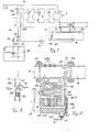
- Figure 1 shows an engine 1 provided with cylinders 2 to which fuel and air are fed through a feed manifold 3.
- the engine I discharges its burnt exhaust gas through the exhaust pipe 4.
- the exhaust pipe 4 is connected to a condenser member 5 by an inlet pipe 6 and return pipe 7.
- the condenser member 5 separates the water contained in the exhaust gas and feeds it through the pipe 8, by way of a pump 9, to an emulsifier apparatus 10 disposed in the line 11 through which fuel is fed to the feed manifold 3, into which it is fed by way of an injector member lla in the case of injection engines.
- the fuel is withdrawn from a tank 12 through the dip tube 13 and filter 14, and is fed by the pump 15.
- the return line 16 to the tank 12 is provided with a valve 17 for adjusting the fuel feed pressure.
- the condenser member 5 is inserted into a duct 18 provided with a cooling fan 19, or alternatively is disposed in a ventilated zone of the vehicle, to ensure its effective cooling.
- the inlet pipe 6 forms a coil 22 provided with fins 23 to increase its heat transfer, and then extends into an also finned multi-tubular unit 24 which opens into a manifold 25 after passing through a filter 26.
- the condensed water collection reservoir 27 is provided below the manifold 25, and the pipe 28 is connected to the return pipe 7 in order to feed uncondensed gas back into the exhaust pipe 4.
- thermoelectric elements 29a fed by thermoelectric elements 29a disposed on the walls of the portion 20 traversed by the high-temperature exhaust gas can conveniently be provided on the walls of the coil 22 to contribute to the cooling of the gas flowing through the coil 22.
- the high-temperature exhaust gas withdrawn from the pipe 6 thus undergoes substantially cooling which causes the water contained therein to condense and accumulate in the collection reservoir 27 from which it is withdrawn in order to be emulsified with the fuel.
- the collection reservoir 27 is provided with a float valve 30 arranged to shut-off passage in the case of lack of water in the reservoir, in order to prevent exhaust gas flowing in such a case to the engine feed fuel.
- the return pipe 7 is inserted into the portion 20 of the exhaust pipe 4 in correspondence with a constriction 31 forming a venturi tube which provides a vacuum for drawing the gas through the condenser member. Should this vacuum be insufficient to ensure circulation of the required throughput, a pump 32 is provided in the pipe 7.
- a pipe 33 branches from the maximum allowable level position in the reservoir 27 and is inserted into the throat of a venturi tube 34 formed in'the pipe 28, to thus ensure that this excess water is drawn off.
- the filter 26, which retains any solid particles present in the exhaust gas which have been removed with the condensed water, can be conveniently of the disposable type, and can be extracted and replaced through an access aperture 35.
- venturi tube 36 in which the fuel, fed through the pipe 11 in the direction of the arrow, undergoes during its passage a pressure drop which draws the water through the atomiser nozzle 37.
- the pressure of the fuel fed by the pump 15 is kept greater than the water pressure in the pipe 8.
- a static emulsifier 40 Downstream of the venturi tube 36 there is a static emulsifier 40, which enables the liquids to be completely emulsified before they are fed into the injector 11a.
- the mixer member In the case of non-supercharged engines, the mixer member, not shown in the figure, consists of a metering and atomising nozzle disposed in the air-fuel mixture feed pipe to the engine downstream of the carburettor, and the water throughput through said metering and atomising nozzle is governed by the vacuum in the feed.
- the apparatus produces water for emulsification in a constant quantity with respect to requirements, without needing large-volume water storage or buffer tanks.
- the condenser member 5 can be fixed rigidly to the body of the engine by way of thermoinsulating elements, or if the exhaust pipe is fixed non-rigidly to the engine block the condenser member can be fixed autonomously to a fixed element of the vehicle and connected to the engine exhaust pipe by flexible hoses.
- the pipes of the apparatus are constructed of corrosion- resistant materials.
- the pipes 6, 7, exposed to high-temperature gas are constructed of stainless steel alloy, whereas the other parts, operating at low temperature, are constructed of plastics material.
Landscapes
- Engineering & Computer Science (AREA)
- Chemical & Material Sciences (AREA)
- Combustion & Propulsion (AREA)
- Mechanical Engineering (AREA)
- General Engineering & Computer Science (AREA)
- Water Supply & Treatment (AREA)
- Health & Medical Sciences (AREA)
- Public Health (AREA)
- Exhaust Gas After Treatment (AREA)
Applications Claiming Priority (2)
| Application Number | Priority Date | Filing Date | Title |
|---|---|---|---|
| IT47523/86A IT1190162B (it) | 1986-01-13 | 1986-01-13 | Apparecchiatura per il recupero di acqua dai gas di scarico di motori a combustione interna e per l'alimentazione della stessa in emulsione nel combustibile |
| IT4752386 | 1986-01-13 |
Publications (2)
| Publication Number | Publication Date |
|---|---|
| EP0233157A2 true EP0233157A2 (de) | 1987-08-19 |
| EP0233157A3 EP0233157A3 (de) | 1988-09-14 |
Family
ID=11260870
Family Applications (1)
| Application Number | Title | Priority Date | Filing Date |
|---|---|---|---|
| EP87830009A Withdrawn EP0233157A3 (de) | 1986-01-13 | 1987-01-13 | Vorrichtung zur Gewinnung von Wasser aus Auspuffgasen einer Brennkraftmaschine und zu dessen Rückführung zum Brennstoff |
Country Status (2)
| Country | Link |
|---|---|
| EP (1) | EP0233157A3 (de) |
| IT (1) | IT1190162B (de) |
Cited By (4)
| Publication number | Priority date | Publication date | Assignee | Title |
|---|---|---|---|---|
| EP0292446A3 (en) * | 1987-05-20 | 1989-10-18 | Ital Idee S.R.L. | Fuel feed device, particularly for internal combustion engines, comprising fuel filtering and emulsifying members |
| WO2005031144A1 (de) * | 2003-09-24 | 2005-04-07 | Munters Euroform Gmbh | Brennkraftmaschineneinheit mit befeuchtungseinrichtung |
| DE102011079927A1 (de) * | 2011-07-27 | 2013-01-31 | Endress + Hauser Conducta Gesellschaft für Mess- und Regeltechnik mbH + Co. KG | Verfahren zur Bestimmung eines Dosiervolumens eines automatischen Peristaltik-Probenehmers |
| DE102015213954A1 (de) * | 2015-07-23 | 2017-01-26 | Bayerische Motoren Werke Aktiengesellschaft | Kondensatgewinnung aus einer Abgasanlage einer Brennkraftmaschine |
Family Cites Families (5)
| Publication number | Priority date | Publication date | Assignee | Title |
|---|---|---|---|---|
| GB1159061A (en) * | 1966-08-03 | 1969-07-23 | Brooks Walker | Internal Combustion Engines having Exhaust Gas Treatment Apparatus. |
| WO1980001190A1 (en) * | 1978-12-11 | 1980-06-12 | E Cottell | Fuel and water emulsification supply system |
| FR2492002A1 (fr) * | 1980-10-10 | 1982-04-16 | Henckel Andre | Dispositif d'injection d'eau dans l'alimentation d'un moteur a combustion interne, ou externe, ou dans un foyer sous pression |
| IT1207972B (it) * | 1983-02-08 | 1989-06-01 | S I E T T E Divisione Iao Ind | Metodo e dispositivo per eliminare la condensa all'interno degli impianti di scarico dei motori acombustione interna |
| JPS6176747A (ja) * | 1984-09-19 | 1986-04-19 | Snow Brand Milk Prod Co Ltd | 内燃機関への酸素添加エマルジヨン燃料の供給方法 |
-
1986
- 1986-01-13 IT IT47523/86A patent/IT1190162B/it active
-
1987
- 1987-01-13 EP EP87830009A patent/EP0233157A3/de not_active Withdrawn
Cited By (4)
| Publication number | Priority date | Publication date | Assignee | Title |
|---|---|---|---|---|
| EP0292446A3 (en) * | 1987-05-20 | 1989-10-18 | Ital Idee S.R.L. | Fuel feed device, particularly for internal combustion engines, comprising fuel filtering and emulsifying members |
| WO2005031144A1 (de) * | 2003-09-24 | 2005-04-07 | Munters Euroform Gmbh | Brennkraftmaschineneinheit mit befeuchtungseinrichtung |
| DE102011079927A1 (de) * | 2011-07-27 | 2013-01-31 | Endress + Hauser Conducta Gesellschaft für Mess- und Regeltechnik mbH + Co. KG | Verfahren zur Bestimmung eines Dosiervolumens eines automatischen Peristaltik-Probenehmers |
| DE102015213954A1 (de) * | 2015-07-23 | 2017-01-26 | Bayerische Motoren Werke Aktiengesellschaft | Kondensatgewinnung aus einer Abgasanlage einer Brennkraftmaschine |
Also Published As
| Publication number | Publication date |
|---|---|
| EP0233157A3 (de) | 1988-09-14 |
| IT1190162B (it) | 1988-02-16 |
| IT8647523A0 (it) | 1986-01-13 |
Similar Documents
| Publication | Publication Date | Title |
|---|---|---|
| US4267802A (en) | Fuel vaporization and delivery system | |
| SE441947B (sv) | Forbrenningsmotor avsedd att drivas med vetgas samt forfarande for drift av motorn | |
| US2461580A (en) | Method and apparatus for emulsifying fuels | |
| US4046119A (en) | Water vapor injection system for internal combustion engines | |
| US3530842A (en) | Vapor injector system | |
| US3141447A (en) | Moisturizers and vaporizers for internal combustion engines | |
| US4611557A (en) | Internal-combustion engine | |
| EP0233157A2 (de) | Vorrichtung zur Gewinnung von Wasser aus Auspuffgasen einer Brennkraftmaschine und zu dessen Rückführung zum Brennstoff | |
| US4409946A (en) | Internal combustion engines | |
| EP0045601A1 (de) | Brennstoffdampfsystem für eine Brennkraftmaschine | |
| US4188928A (en) | Fuel vaporizing apparatus for internal combustion engines | |
| US4569322A (en) | Hot plate fuel vaporizer | |
| US4419967A (en) | Method and apparatus for utilizing ethanol of any purity as a fuel in 4-stroke internal combustion engines | |
| US4233945A (en) | Carburetion in an internal combustion engine | |
| US4603672A (en) | Fuel vaporizer for internal combustion engine | |
| US3294381A (en) | Carburetor | |
| US4108126A (en) | Fuel feed device of an internal combustion engine | |
| US2252415A (en) | Process and apparatus for providing internal combustion engines with explosive charges | |
| US4345568A (en) | Multi-fuel vapor charger carburetion system and device therefor | |
| US1610508A (en) | Mixture humidifier for explosive engines | |
| US4129106A (en) | Vapor lock and fuel vaporization controls | |
| EP0020711B1 (de) | Emulgiersystem für brennstoff und wasser | |
| CA1234026A (en) | Internal-combustion engine | |
| US4667643A (en) | Heated fuel vapourizer and slidable throttle valve | |
| US5694888A (en) | Fuel consumption optimizer and exhaust emissions reducer based on an air-vacuum liquid compensation system |
Legal Events
| Date | Code | Title | Description |
|---|---|---|---|
| PUAI | Public reference made under article 153(3) epc to a published international application that has entered the european phase |
Free format text: ORIGINAL CODE: 0009012 |
|
| AK | Designated contracting states |
Kind code of ref document: A2 Designated state(s): AT BE CH DE ES FR GB GR LI LU NL SE |
|
| PUAL | Search report despatched |
Free format text: ORIGINAL CODE: 0009013 |
|
| AK | Designated contracting states |
Kind code of ref document: A3 Designated state(s): AT BE CH DE ES FR GB GR LI LU NL SE |
|
| STAA | Information on the status of an ep patent application or granted ep patent |
Free format text: STATUS: THE APPLICATION IS DEEMED TO BE WITHDRAWN |
|
| 18D | Application deemed to be withdrawn |
Effective date: 19890315 |
|
| RIN1 | Information on inventor provided before grant (corrected) |
Inventor name: CANTONI, ANGELO |