EP0233237B1 - Kernspintomographie von hochgeschwindigkeitsströmungen mit geringer radiofrequenzbelastung - Google Patents
Kernspintomographie von hochgeschwindigkeitsströmungen mit geringer radiofrequenzbelastung Download PDFInfo
- Publication number
- EP0233237B1 EP0233237B1 EP86904859A EP86904859A EP0233237B1 EP 0233237 B1 EP0233237 B1 EP 0233237B1 EP 86904859 A EP86904859 A EP 86904859A EP 86904859 A EP86904859 A EP 86904859A EP 0233237 B1 EP0233237 B1 EP 0233237B1
- Authority
- EP
- European Patent Office
- Prior art keywords
- pulses
- read
- pulse
- slice selection
- gradient
- Prior art date
- Legal status (The legal status is an assumption and is not a legal conclusion. Google has not performed a legal analysis and makes no representation as to the accuracy of the status listed.)
- Expired - Lifetime
Links
- 238000002595 magnetic resonance imaging Methods 0.000 title claims description 9
- 230000005284 excitation Effects 0.000 claims abstract description 27
- 230000005291 magnetic effect Effects 0.000 claims abstract description 23
- 230000000295 complement effect Effects 0.000 claims abstract description 6
- 238000000034 method Methods 0.000 claims description 40
- 238000001208 nuclear magnetic resonance pulse sequence Methods 0.000 claims description 23
- 230000035945 sensitivity Effects 0.000 claims description 12
- 239000000126 substance Substances 0.000 claims description 5
- 230000001131 transforming effect Effects 0.000 claims 3
- 230000010363 phase shift Effects 0.000 abstract description 14
- 230000015654 memory Effects 0.000 abstract description 11
- 238000003384 imaging method Methods 0.000 description 26
- 230000000747 cardiac effect Effects 0.000 description 18
- 239000000463 material Substances 0.000 description 17
- 230000005415 magnetization Effects 0.000 description 13
- 230000017531 blood circulation Effects 0.000 description 9
- 230000000694 effects Effects 0.000 description 9
- 238000013507 mapping Methods 0.000 description 8
- 239000008280 blood Substances 0.000 description 7
- 210000004369 blood Anatomy 0.000 description 7
- 238000005259 measurement Methods 0.000 description 7
- 238000005481 NMR spectroscopy Methods 0.000 description 6
- 230000001419 dependent effect Effects 0.000 description 6
- 230000008901 benefit Effects 0.000 description 5
- 238000002592 echocardiography Methods 0.000 description 5
- 230000003068 static effect Effects 0.000 description 4
- 238000006073 displacement reaction Methods 0.000 description 3
- 239000012530 fluid Substances 0.000 description 3
- 238000000264 spin echo pulse sequence Methods 0.000 description 3
- 230000004075 alteration Effects 0.000 description 2
- 230000002238 attenuated effect Effects 0.000 description 2
- 210000004204 blood vessel Anatomy 0.000 description 2
- 230000006870 function Effects 0.000 description 2
- 238000010438 heat treatment Methods 0.000 description 2
- 238000012986 modification Methods 0.000 description 2
- 230000004048 modification Effects 0.000 description 2
- 238000012544 monitoring process Methods 0.000 description 2
- 230000010287 polarization Effects 0.000 description 2
- 230000009467 reduction Effects 0.000 description 2
- 238000003325 tomography Methods 0.000 description 2
- 230000002411 adverse Effects 0.000 description 1
- 210000000709 aorta Anatomy 0.000 description 1
- 238000010420 art technique Methods 0.000 description 1
- 239000013060 biological fluid Substances 0.000 description 1
- 210000001715 carotid artery Anatomy 0.000 description 1
- 230000015556 catabolic process Effects 0.000 description 1
- 230000008859 change Effects 0.000 description 1
- 230000001427 coherent effect Effects 0.000 description 1
- 210000004351 coronary vessel Anatomy 0.000 description 1
- 238000013480 data collection Methods 0.000 description 1
- 238000006731 degradation reaction Methods 0.000 description 1
- 230000003111 delayed effect Effects 0.000 description 1
- 230000008021 deposition Effects 0.000 description 1
- 230000008030 elimination Effects 0.000 description 1
- 238000003379 elimination reaction Methods 0.000 description 1
- 229940082150 encore Drugs 0.000 description 1
- 125000004435 hydrogen atom Chemical group [H]* 0.000 description 1
- 230000006872 improvement Effects 0.000 description 1
- 238000001727 in vivo Methods 0.000 description 1
- 230000000670 limiting effect Effects 0.000 description 1
- 238000013421 nuclear magnetic resonance imaging Methods 0.000 description 1
- 230000036961 partial effect Effects 0.000 description 1
- 230000008569 process Effects 0.000 description 1
- 230000000750 progressive effect Effects 0.000 description 1
- 210000001147 pulmonary artery Anatomy 0.000 description 1
- 230000002829 reductive effect Effects 0.000 description 1
- 229920006395 saturated elastomer Polymers 0.000 description 1
- 238000004904 shortening Methods 0.000 description 1
- 239000007787 solid Substances 0.000 description 1
- 230000009466 transformation Effects 0.000 description 1
- 230000001960 triggered effect Effects 0.000 description 1
- 238000004804 winding Methods 0.000 description 1
Images

Classifications
-
- G—PHYSICS
- G01—MEASURING; TESTING
- G01R—MEASURING ELECTRIC VARIABLES; MEASURING MAGNETIC VARIABLES
- G01R33/00—Arrangements or instruments for measuring magnetic variables
- G01R33/20—Arrangements or instruments for measuring magnetic variables involving magnetic resonance
- G01R33/44—Arrangements or instruments for measuring magnetic variables involving magnetic resonance using nuclear magnetic resonance [NMR]
- G01R33/48—NMR imaging systems
- G01R33/54—Signal processing systems, e.g. using pulse sequences ; Generation or control of pulse sequences; Operator console
- G01R33/56—Image enhancement or correction, e.g. subtraction or averaging techniques, e.g. improvement of signal-to-noise ratio and resolution
- G01R33/565—Correction of image distortions, e.g. due to magnetic field inhomogeneities
- G01R33/56509—Correction of image distortions, e.g. due to magnetic field inhomogeneities due to motion, displacement or flow, e.g. gradient moment nulling
-
- G—PHYSICS
- G01—MEASURING; TESTING
- G01F—MEASURING VOLUME, VOLUME FLOW, MASS FLOW OR LIQUID LEVEL; METERING BY VOLUME
- G01F1/00—Measuring the volume flow or mass flow of fluid or fluent solid material wherein the fluid passes through a meter in a continuous flow
- G01F1/704—Measuring the volume flow or mass flow of fluid or fluent solid material wherein the fluid passes through a meter in a continuous flow using marked regions or existing inhomogeneities within the fluid stream, e.g. statistically occurring variations in a fluid parameter
- G01F1/708—Measuring the time taken to traverse a fixed distance
- G01F1/716—Measuring the time taken to traverse a fixed distance using electron paramagnetic resonance [EPR] or nuclear magnetic resonance [NMR]
-
- G—PHYSICS
- G01—MEASURING; TESTING
- G01R—MEASURING ELECTRIC VARIABLES; MEASURING MAGNETIC VARIABLES
- G01R33/00—Arrangements or instruments for measuring magnetic variables
- G01R33/20—Arrangements or instruments for measuring magnetic variables involving magnetic resonance
- G01R33/44—Arrangements or instruments for measuring magnetic variables involving magnetic resonance using nuclear magnetic resonance [NMR]
- G01R33/48—NMR imaging systems
- G01R33/4818—MR characterised by data acquisition along a specific k-space trajectory or by the temporal order of k-space coverage, e.g. centric or segmented coverage of k-space
- G01R33/482—MR characterised by data acquisition along a specific k-space trajectory or by the temporal order of k-space coverage, e.g. centric or segmented coverage of k-space using a Cartesian trajectory
-
- G—PHYSICS
- G01—MEASURING; TESTING
- G01R—MEASURING ELECTRIC VARIABLES; MEASURING MAGNETIC VARIABLES
- G01R33/00—Arrangements or instruments for measuring magnetic variables
- G01R33/20—Arrangements or instruments for measuring magnetic variables involving magnetic resonance
- G01R33/44—Arrangements or instruments for measuring magnetic variables involving magnetic resonance using nuclear magnetic resonance [NMR]
- G01R33/48—NMR imaging systems
- G01R33/54—Signal processing systems, e.g. using pulse sequences ; Generation or control of pulse sequences; Operator console
-
- G—PHYSICS
- G01—MEASURING; TESTING
- G01R—MEASURING ELECTRIC VARIABLES; MEASURING MAGNETIC VARIABLES
- G01R33/00—Arrangements or instruments for measuring magnetic variables
- G01R33/20—Arrangements or instruments for measuring magnetic variables involving magnetic resonance
- G01R33/44—Arrangements or instruments for measuring magnetic variables involving magnetic resonance using nuclear magnetic resonance [NMR]
- G01R33/48—NMR imaging systems
- G01R33/54—Signal processing systems, e.g. using pulse sequences ; Generation or control of pulse sequences; Operator console
- G01R33/56—Image enhancement or correction, e.g. subtraction or averaging techniques, e.g. improvement of signal-to-noise ratio and resolution
- G01R33/563—Image enhancement or correction, e.g. subtraction or averaging techniques, e.g. improvement of signal-to-noise ratio and resolution of moving material, e.g. flow contrast angiography
- G01R33/56308—Characterization of motion or flow; Dynamic imaging
-
- G—PHYSICS
- G01—MEASURING; TESTING
- G01R—MEASURING ELECTRIC VARIABLES; MEASURING MAGNETIC VARIABLES
- G01R33/00—Arrangements or instruments for measuring magnetic variables
- G01R33/20—Arrangements or instruments for measuring magnetic variables involving magnetic resonance
- G01R33/44—Arrangements or instruments for measuring magnetic variables involving magnetic resonance using nuclear magnetic resonance [NMR]
- G01R33/48—NMR imaging systems
- G01R33/54—Signal processing systems, e.g. using pulse sequences ; Generation or control of pulse sequences; Operator console
- G01R33/56—Image enhancement or correction, e.g. subtraction or averaging techniques, e.g. improvement of signal-to-noise ratio and resolution
- G01R33/563—Image enhancement or correction, e.g. subtraction or averaging techniques, e.g. improvement of signal-to-noise ratio and resolution of moving material, e.g. flow contrast angiography
- G01R33/56308—Characterization of motion or flow; Dynamic imaging
- G01R33/56316—Characterization of motion or flow; Dynamic imaging involving phase contrast techniques
Definitions
- the present invention relates to the art of magnetic resonance imaging of moving substances and velocity determination by phase mapping. It finds particular application in conjunction with measuring blood flow and will be described with particular reference thereto. However, it is to be appreciated that the invention is also applicable to imaging or phase mapping other anatomical tissue movement, non-biological fluid flows, multicomponent systems in which one gaseous, fluid, semi-fluid, solid, or other component moves relative to other components, or the like.
- the spin-echo magnetic resonance imaging signal from material flowing through a field gradient experiences a phase shift.
- the spin-echo imaging and phase mapping have been used to measure velocities of slow moving, uniform flows, including blood flows in vivo.
- varying flow rates cause corresponding variations in the phase shift which interferes with the phase encoding.
- These phase variations result in noise which extends from the blood vessel across the image in the phase encoding direction. This is particularly serious at high flow velocities at which there are frequently small velocity variations and eddy currents which cause significant phase shifts.
- High blood flow rates of clinical interest occur in the coronary, carotid, and pulmonary arteries and the aorta.
- phase shift at each pixel is dependent on the flow in both the read and the slice select direction. Although the relative phase shift at each pixel may be rendered sensitive to flow in only a single direction, the high sensitivity to flow velocity variations remains. Commonly, a phase shift of greater than 20 degrees for each centimeter per second of velocity change is experienced.
- the velocity sensitivity has two adverse effects on the resultant image.
- magnetic resonance signals are phase dependent on the varying phase-encode field gradient.
- the two dimensional Fourier transform method of spatially mapping the magnetic resonance signals identifies signal components arising from different positions along the phase-encode gradient. As the gradient is incremented to collect a plurality of views, the signal arising from a given position changes in phase by an amount proportional to its position. Spatial resolution is improved by the Fourier transformation of the signals acquired over a plurality of views or increments of the phase encoded gradient, e.g. 256 views.
- phase dependence of the magnetic resonance signal on velocity introduces an extra term in the phase encoding process.
- the extra term has no effect on the spatial resolution.
- the velocity changes from view to view such as from turbulence or minor irregularities in heart rate or ejection volume
- the associated phase changes are interpreted as noise when decoding the spatial position of the resonance signal component.
- the available signal intensity is dispersed through the image in the phase encoding dimension or direction. This prevents signal phase, hence, velocity determination.
- the second effect of the velocity sensitivity is a reduction in the signal intensity from vessels flowing in the read direction by phase cancellation through a flow profile.
- laminar flow through a circular pipe lying within the selected slice has a flow profile which is parabolic.
- the maximum flow velocity is at the center of the pipe, while the flow velocity is zero at the boundary with the wall.
- one resultant resonance signal represents the projection or integral of the signal components from columns of incremental volume elements extending across the pipe.
- the component from each incremental volume element has the same intensity but each has a phase which is proportional to the local velocity.
- Summing or projecting the phases in the column across the pipe sums components from incremental volume elements which have the generally parabolic range of velocities.
- phase cancellation This summation of signal components across the pipe leads to signal attenuation by phase cancellation.
- phase sensitivity to velocity increases, the phase cancellation becomes greater.
- attenuations of over 75% have been encountered.
- the attenuation is lower attributable to the non-Newtonian nature of blood. Blood travels through the body with a flow which approximates plug flow more closely than laminar flow.
- broadband refocusing pulses introduce another problem in blood and other materials with relatively long relaxation times.
- Material outside the selected slice is subject to a series of the broadband refocusing pulses arising from repetition of the imaging sequence. This has the effect of inverting Z-magnetization at every repetition of the imaging sequence, typically at least every second.
- the inversion pulses then cause a progressive saturation of the material outside the slice until a semi-saturated steady state polarization is reached. When this material moves into the slice, it produces a signal proportional to this polarization. Partial saturation then produces a corresponding reduction in signal intensity. For example, when imaging blood with a 20 ms spin-echo sequence repeated every one second, the intensity is reduced approximately 45% relative to fully polarized blood.
- the reconstruction technique of EP-A-0233906 has certain drawbacks relative to the present improvement.
- the R.F. characteristics of the EP-A-0233906 imaging sequence limit data collection to one echo signal measurement per heart beat
- the imaging sequence duration contributes to a degradation in resolution and accuracy in rapidly accelerating flows and an increase in larger R.F. dosages and heating.
- artifacts attributable to transverse magnetization arising from the spin-echo refocusing pulse are commonly removed by acquiring a second data set with a phase-inverted refocusing pulse.
- the collection and combining of two data sets doubles the acquisition time, undesirable from patient consideration.
- EP-A-0142343 there is described a spin-echo nuclear magnetic resonance imaging technique for acquiring signals which are substantially insensitive to motion in a given direction wherein there are applied gradient pulse sequences which exhibit zero value first moments in time. This specification also describes comparing an image produced using such a technique with a corresponding image in which motion effects are represented and using the results to make a velocity histogram of motion.
- the present invention provides a technique which provides signals having a desired sensitivity to motion which avoids the use of spin-echoes.
- the invention provides a method of magnetic resonance imaging an object comprising the steps of: applying a resonance excitation pulse; applying a slice selection magnetic field gradient pulse sequence; applying a phase encode magnetic field gradient; and collecting an echo resonance signal; at least one of the slice selection and read gradient pulse sequences being such that the effective first moment in time of that pulse sequence is substantially zero, thereby to cause the echo signal to be substantially insensitive to motion of the object; characterised in that said at least one of the slice selection and read pulse sequences includes complementary pulses of a like product of duration and amplitude between the resonance excitation pulse and the echo signal and of opposite polarity such that the collected signal is a field gradient echo resonance signal.
- the invention also provides a method of magnetic resonance imaging moving substances comprising the steps of: applying a resonance excitation pulse; applying a plurality of slice selection magnetic field gradient pulses of opposite polarity; applying a read magnetic field gradient pulse sequence between application of the resonance excitation pulse and collection of the resonance echo signal; the slice selection and/or read gradient pulses being chosen so that the collected signal exhibits a desired sensitivity to motion of the moving substances characterised in that the slice selection and read pulse sequences are such that the collected signal is a field gradient echo resonance signal; and in that the steps of the method are repeated with at least one of the slice selection pulses and read pulses altered so that the collected field echo signal has a sensitivity to motion different from that of the previously collected field echo signal.
- One advantage of the present invention is that the image sequence is sufficiently fast to successfully phase map high flow velocities.
- Another advantage resides in the mapping of flows which include turbulence, beat variation, and other non- constant flow components.
- the present invention is further advantageous in that the imaging sequence is sufficiently short that multiple sequences can be applied during each cardiac cycle.
- the shorter pulse squence enables more rapid imaging and improved imaging of rapidly accelerating flows.
- the use of repeated imaging sequences during a single cardiac cycle enhances contrast between static and flowing materials.
- a further advantage resides in reducing R.F. dosage, associated tissue heating, and R.F. power consumption by eliminating broadband inversion pulses.
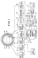
- the magnetic resonance imaging apparatus includes a plurality of magnetics 10 and a control circuit 12 therefor that generate a substantially uniform magnetic field linearly through an image region 14.
- a radio frequency (R.F.) coil 20 is connected with a resonance excitation control circuit or means 22 which selectively causes the R.F. coil to transmit a resonance excitation pulse, such as a 90 degree pulse.
- a radio frequency receiver 24 receives radio frequency resonance signal components generated by resonating nuclei in the image region. Separate transmit and receive coils may be provided orthe R.F. coil 20 may function alternately as a transmitter and as a receiving antenna.
- a gradient coil 30 includes the appropriate windings for causing gradients across the main magnetic field in the image region atselectable angles and with selectable durations and periodicity.
- a slice selection gradient control means or circuit 32 selectively applies electrical power to the gradient coil 30 to select a slice or plane in the image region 14 to be phase mapped. Commonly, the slice is selected by applying a linear field gradient across the image region and applying a narrow band excitation pulse to excite spins over a limited range of resonance frequencies.
- a read gradient control 34 selectively applies a read gradient across the image region.
- a phase encoder or means 36 selectively adjusts the gradients so as to cause a phase shift which varies with spatial position such that the resonance signal is spatially encoded.
- a transform means 40 transforms or maps discretely sampled values of the received resonance signal from a phase domain to a spatial domain.
- a fast Fourier transform algorithm transforms or maps the received resonance signal from each field or gradient echo to generate real and imaginary components of a corresponding view in the spatial domain.
- a switching or selection means 52 channels to a first memory 54 separate real components A cos a and imaginary components A sin of views of the same phase in the cardiac cycle.
- the views are summed pixel by pixel, in the first memory to produce a first image representation in which the phase is substantially independent of flow velocity.
- Real components B cos and imaginary components B sin of views or resonance data of the same phase in the cardiac cycle which are encoded with information on the moving portions of the object as discussed above are channelled by the switch means 52 into a second memory 56.
- images at the other phases of the cardiac cycle may be generated if views from several phases of the cardiac cycle are stored in the mass memory means 50.
- a threshold means 58 compares the magnitude of the value stored at each pixel in the real and imaginary portions of the first and second memories to determine whether the stored value exceeds a preselected threshold level. If the threshold level is not exceeded, the data values are discarded. Values above the threshold level are utilized by a phase difference determining means 60 to determine the phase difference a - ⁇ which, of course, varies with the flow.
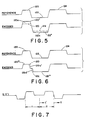
- a slice select gradient pulse sequence includes a pulse 112 of a first polarity which is applied during the application of the excitation pulse 100, a complementary pulse 114 of a second polarity, and a third pulse 116 of the first polarity.
- the three pulses are preferably of identical amplitudes, with durations such that pulse 116 is of half the duration of pulse 114 and approximately matches that section of pulse 112 occuring after the center of the excitation pulse 100.
- the magnitudes and durations of the pulses contained in the slice-selection gradient sequence are selected such that the magnetization of material moving perpendicular to the slice plane is rephased.
- the even-echo rephasing technique is applied to tailor the read gradient pulse-sequence to achieve rephasing of magnetization moving parallel to the read axis.
- a read gradient pulse 120 is followed by a pulse 122 of a second polarity and a third pulse 124 of the first polarity, applied contemporaneously with the monitored field echo data 102.
- Pulses 120,122,124 are preferably of identical amplitudes, with durations such that pulse 120 is of half the duration of pulse 122 and approximately matches that section of pulse 124 occuring before the center of the field echo 102.
- the magnitudes and durations of the pulses contained in the read gradient sequence are selected such that the magnetization of material moving parallel to the read axis is rephased.
- Pulses 120, 124 may be applied contemporaneously with pulses 112,114 and a phase encode pulse 130 if required, butthis is not a requirement of the invention.
- phase encode pulse 130 During the phase encoding pulse, one of a selected plurality of phases are encoded.
- shifting either pulse will reveal flow velocities, but only the absolute flow multiplied by its direction cosine.
- the oblique angle obtained by shifting both pulses is defined by the relative phase sensitivity of the two gradients. For example, shifts causing twice the phase sensitivity to flow in the read direction than in the slice selection direction will be most sensitive to flow angled 26 degrees (an arctangent of 0.5) from the read axis and be insensitive to flow perpendicular to this direction.
- the read gradient pulses 120 and 122 can be shortened equally to pulses 120"' and 122"'.
- the decrease in area 120a' and 122a' are equal such that the first and second polarity portions of the pulse sequence between the excitation pulse 100 and the echo 102 remain equal. That is, the zeroth moment remains zero although the first moment changes.
- pulses 122 and 124 may be time sealed in a like manner.
- the gradient pulses 114 and 116 or pulses 112 and 114 of the slice selection gradient sequence may be time scaled analogously.
- the multiple repetition of the sequence allows measurements of the blood flow velocity at various points during the cardiac cycle.
- the relaxation factor in Equation (2) i.e., all the terms except the sine term
- the reconstructed images and phase maps show contrast enhancement between flowing and stationary material. This occurs primarily when the Ernst angle is exceeded, i.e., when cos 8 is less than exp(-Tr/TI) and when the repeat time Tr is less than the longitudinal relaxation time TI.
- gradient pulsing limitations tend to limit the repeat time Tr to a minimum of about 50 ms. It might be noted that the slice definition of the static material may be degraded when the flip angle 0 of the R.F. pulse varies across the slice and the central flip angle is greater than the Ernst angle.
- gradient pulses of approximately one kilohertz per centimeter held for4 milliseconds can code velocities up to one meter per second when time shifted by 1.25 milliseconds.
- the read gradients are shifted analogously.
- Concurrent encoding in both the read and slice select directions may be achieved analogously or shifting or scaling the amplitudes of both gradients.
Landscapes
- Physics & Mathematics (AREA)
- General Physics & Mathematics (AREA)
- High Energy & Nuclear Physics (AREA)
- Condensed Matter Physics & Semiconductors (AREA)
- Nuclear Medicine, Radiotherapy & Molecular Imaging (AREA)
- Engineering & Computer Science (AREA)
- Signal Processing (AREA)
- Health & Medical Sciences (AREA)
- Radiology & Medical Imaging (AREA)
- General Health & Medical Sciences (AREA)
- Vascular Medicine (AREA)
- Fluid Mechanics (AREA)
- Magnetic Resonance Imaging Apparatus (AREA)
Claims (17)
Applications Claiming Priority (4)
| Application Number | Priority Date | Filing Date | Title |
|---|---|---|---|
| US06/766,757 US4683431A (en) | 1985-08-16 | 1985-08-16 | Magnetic resonance imaging of high velocity flows |
| US766757 | 1985-08-16 | ||
| US798750 | 1985-11-15 | ||
| US06/798,750 US4689560A (en) | 1985-08-16 | 1985-11-15 | Low R.F. dosage magnetic resonance imaging of high velocity flows |
Publications (2)
| Publication Number | Publication Date |
|---|---|
| EP0233237A1 EP0233237A1 (de) | 1987-08-26 |
| EP0233237B1 true EP0233237B1 (de) | 1991-09-11 |
Family
ID=27117798
Family Applications (1)
| Application Number | Title | Priority Date | Filing Date |
|---|---|---|---|
| EP86904859A Expired - Lifetime EP0233237B1 (de) | 1985-08-16 | 1986-07-31 | Kernspintomographie von hochgeschwindigkeitsströmungen mit geringer radiofrequenzbelastung |
Country Status (4)
| Country | Link |
|---|---|
| US (1) | US4689560A (de) |
| EP (1) | EP0233237B1 (de) |
| DE (1) | DE3681436D1 (de) |
| WO (1) | WO1987001201A1 (de) |
Families Citing this family (24)
| Publication number | Priority date | Publication date | Assignee | Title |
|---|---|---|---|---|
| FR2602869B1 (fr) * | 1986-08-14 | 1989-03-31 | Thomson Cgr | Procede d'application des impulsions de gradient dans une experimentation d'imagerie au moyen d'une machine de resonance magnetique nucleaire |
| JPH0814584B2 (ja) * | 1986-12-22 | 1996-02-14 | 株式会社東芝 | 磁気共鳴イメ−ジング装置における流速測定方法 |
| US4912412A (en) * | 1987-02-27 | 1990-03-27 | Hitachi, Ltd. | MR imaging method and apparatus |
| US5124649A (en) * | 1987-06-02 | 1992-06-23 | Picker International, Inc. | Magnetic resonance imaging with selective phase encoding averaging |
| NL8701642A (nl) * | 1987-07-13 | 1989-02-01 | Philips Nv | Werkwijze en inrichting voor het uitvoeren van een fasecorrectie bij mr angiografie. |
| DE3726932A1 (de) * | 1987-08-13 | 1989-02-23 | Spectrospin Ag | Verfahren zum kodieren von n parametern bei der mehrdimensionalen fourier-nmr-spektroskopie |
| JPH0634785B2 (ja) * | 1988-02-05 | 1994-05-11 | 株式会社日立メディコ | 核磁気共鳴イメージング装置 |
| IL86231A (en) * | 1988-04-29 | 1991-07-18 | Elscint Ltd | Correction for eddy current caused phase degradation |
| US4881032A (en) * | 1988-10-21 | 1989-11-14 | General Electric Company | Method of, and apparatus for, NMR spectroscopic metabolite imaging and quantification |
| US5115812A (en) * | 1988-11-30 | 1992-05-26 | Hitachi, Ltd. | Magnetic resonance imaging method for moving object |
| US4918386A (en) * | 1988-12-23 | 1990-04-17 | General Electric Company | Method for simultaneously obtaining three-dimensional NMR angiograms and stationary tissue NMR images |
| US5034694A (en) * | 1989-11-22 | 1991-07-23 | Picker International, Inc. | Minimum basis set MR angiography |
| EP0447970B1 (de) * | 1990-03-20 | 1997-09-10 | Kabushiki Kaisha Toshiba | Verfahren und Apparat zur Bilderzeugung von Blutgefässen mittels magnetischer Resonanz |
| US5101156A (en) * | 1990-08-09 | 1992-03-31 | General Electric | Rapid flow measurement using an nmr imaging system |
| US5093620A (en) * | 1990-08-09 | 1992-03-03 | General Electric | Encoding for nmr phase contrast flow measurement |
| US5348011A (en) * | 1991-11-14 | 1994-09-20 | Picker International, Inc. | Shared excitation phase encode grouping for improved throughput cardiac gated MRI cine imaging |
| US5329925A (en) * | 1991-11-14 | 1994-07-19 | Picker International, Inc. | Reduced scan time cardiac gated magnetic resonance cine and flow imaging |
| US5261282A (en) * | 1992-03-03 | 1993-11-16 | Kraft General Foods, Inc. | Method and apparatus for monitoring a continuous cooking process based on particulate residence time |
| US5408180A (en) * | 1993-08-13 | 1995-04-18 | Wisconsin Alumni Research Foundation | Measurement of flow using a complex difference method of magnetic resonance imaging |
| DE4402646C1 (de) * | 1994-01-29 | 1995-06-22 | Bruker Medizintech | Magnetresonanzmessung mit geschaltetem Phasenkodiergradienten |
| US5810727A (en) * | 1996-04-24 | 1998-09-22 | U.S. Philips Corporation | Method of and device for the imaging of objects by means of magnetic resonance |
| US6245027B1 (en) * | 1998-04-10 | 2001-06-12 | Noam Alperin | Method of measuring intracranial pressure |
| US7180288B2 (en) * | 2004-11-10 | 2007-02-20 | Schlumberger Technology Corporation | Downhole NMR flow and formation characterization while sampling fluids |
| DE102005008753B4 (de) * | 2005-02-25 | 2007-09-27 | Siemens Ag | Verfahren zur Darstellung von Fluss in einem Magnetresonanzbild |
Family Cites Families (15)
| Publication number | Priority date | Publication date | Assignee | Title |
|---|---|---|---|---|
| GB1596160A (en) * | 1976-12-15 | 1981-08-19 | Nat Res Dev | Nuclear magnetic resonance apparatus and methods |
| GB2107469B (en) * | 1981-09-21 | 1985-09-18 | Peter Mansfield | Nuclear magnetic resonance methods |
| US4528985A (en) * | 1981-12-21 | 1985-07-16 | Albert Macovski | Blood vessel imaging system using nuclear magnetic resonance |
| EP0103372A3 (de) * | 1982-08-11 | 1986-05-07 | Picker International Limited | Kernmagnetische Resonanzmethode und -Vorrichtung |
| GB2127155B (en) * | 1982-09-17 | 1987-04-08 | Picker Int Ltd | Flow determination by nuclear magnetic resonance |
| US4516075A (en) * | 1983-01-04 | 1985-05-07 | Wisconsin Alumni Research Foundation | NMR scanner with motion zeugmatography |
| US4551680A (en) * | 1983-04-21 | 1985-11-05 | Albert Macovski | Selective region NMR projection imaging system |
| US4516582A (en) * | 1983-05-02 | 1985-05-14 | General Electric Company | NMR blood flow imaging |
| US4532473A (en) * | 1983-05-18 | 1985-07-30 | General Electric Company | NMR method for measuring and imaging fluid flow |
| US4574239A (en) * | 1983-07-19 | 1986-03-04 | The Regents Of The University Of California | Method for flow measurement using nuclear magnetic resonance |
| US4602641A (en) * | 1983-08-15 | 1986-07-29 | The Regents Of The University Of California | Method and apparatus for NMR detection and imaging of flowing fluid nuclei |
| US4649346A (en) * | 1983-11-09 | 1987-03-10 | Technicare Corporation | Complex quotient nuclear magnetic resonance imaging |
| US4616180A (en) * | 1983-11-14 | 1986-10-07 | Technicare Corporation | Nuclear magnetic resonance imaging with reduced sensitivity to motional effects |
| US4595879A (en) * | 1983-11-14 | 1986-06-17 | Technicare Corporation | Nuclear magnetic resonance flow imaging |
| US4570119A (en) * | 1983-11-15 | 1986-02-11 | General Electric Company | Method for visualization of in-plane fluid flow by proton NMR imaging |
-
1985
- 1985-11-15 US US06/798,750 patent/US4689560A/en not_active Expired - Lifetime
-
1986
- 1986-07-31 DE DE8686904859T patent/DE3681436D1/de not_active Expired - Lifetime
- 1986-07-31 WO PCT/GB1986/000459 patent/WO1987001201A1/en not_active Ceased
- 1986-07-31 EP EP86904859A patent/EP0233237B1/de not_active Expired - Lifetime
Non-Patent Citations (1)
| Title |
|---|
| Journal of Computer Assisted Tomography, vol 8, no 4, August 1984 (New York US) pages 588-593 * |
Also Published As
| Publication number | Publication date |
|---|---|
| DE3681436D1 (de) | 1991-10-17 |
| EP0233237A1 (de) | 1987-08-26 |
| US4689560A (en) | 1987-08-25 |
| WO1987001201A1 (en) | 1987-02-26 |
Similar Documents
| Publication | Publication Date | Title |
|---|---|---|
| EP0233237B1 (de) | Kernspintomographie von hochgeschwindigkeitsströmungen mit geringer radiofrequenzbelastung | |
| EP0233906B1 (de) | Kernspintomographie von hochgeschwindigkeitsströmungen | |
| O'donnell | NMR blood flow imaging using multiecho, phase contrast sequences | |
| Hawkes et al. | Rapid Fourier imaging using steady‐state free precession | |
| US6891373B2 (en) | Method to determine the ADC coefficients in diffusion-weighted magnetic resonance imaging given use of steady-state sequences | |
| EP0498570B1 (de) | Quantitative Messung der Blutdurchströmung bei Anwendung von zylindrisch örtlicher Fourrier-Geschwindigkeitskodierung | |
| EP0171070B1 (de) | Abbildung des Blutflusses mittels magnetischer Kernresonanz durch Phasenkontrast vom Mehrfach-Echo | |
| US5233298A (en) | Quantitative measurement of blood flow at multiple positions using comb excitation and fourier velocity encoding | |
| US4718424A (en) | NMR imaging of blood flow by moment variation of magnetic gradients | |
| EP0126381A1 (de) | Messung und Abbildung eines Flüssigkeitsflusses mittels kernmagnetischer Resonanz | |
| Gatenby et al. | Mechanisms of signal loss in magnetic resonance imaging of stenoses | |
| US5300886A (en) | Method to enhance the sensitivity of MRI for magnetic susceptibility effects | |
| US4731583A (en) | Method for reduction of MR image artifacts due to flowing nuclei by gradient moment nulling | |
| CN103597370A (zh) | 空间编码的相位对比磁共振成像 | |
| US4574240A (en) | Method for flow measurement using nuclear magnetic resonance | |
| US4574239A (en) | Method for flow measurement using nuclear magnetic resonance | |
| JP2769473B2 (ja) | Nmrにより身体内の体積素の運動を表示する装置 | |
| Duerk | Principles of MR image formation and reconstruction | |
| US4862080A (en) | Method of deriving a spin resonance signal from a moving fluid, and device for performing this method | |
| GB2201794A (en) | Magnetic resonance imaging system | |
| Madio et al. | Ultra‐fast velocity imaging in stenotically produced turbulent jets using RUFIS | |
| Kittler et al. | Real-time fluid transport characterization through direct acquisition of the averaged propagator | |
| Oh et al. | Study of RF, gradient pulse and magnet instability effect in NMR tomography | |
| Loecher et al. | k-Space | |
| Blum et al. | Fast magnetic resonance imaging using spiral trajectories |
Legal Events
| Date | Code | Title | Description |
|---|---|---|---|
| PUAI | Public reference made under article 153(3) epc to a published international application that has entered the european phase |
Free format text: ORIGINAL CODE: 0009012 |
|
| 17P | Request for examination filed |
Effective date: 19870413 |
|
| AK | Designated contracting states |
Kind code of ref document: A1 Designated state(s): DE GB NL |
|
| 17Q | First examination report despatched |
Effective date: 19890609 |
|
| GRAA | (expected) grant |
Free format text: ORIGINAL CODE: 0009210 |
|
| AK | Designated contracting states |
Kind code of ref document: B1 Designated state(s): DE GB NL |
|
| REF | Corresponds to: |
Ref document number: 3681436 Country of ref document: DE Date of ref document: 19911017 |
|
| PLBE | No opposition filed within time limit |
Free format text: ORIGINAL CODE: 0009261 |
|
| STAA | Information on the status of an ep patent application or granted ep patent |
Free format text: STATUS: NO OPPOSITION FILED WITHIN TIME LIMIT |
|
| 26N | No opposition filed | ||
| PGFP | Annual fee paid to national office [announced via postgrant information from national office to epo] |
Ref country code: GB Payment date: 19960612 Year of fee payment: 11 |
|
| PG25 | Lapsed in a contracting state [announced via postgrant information from national office to epo] |
Ref country code: GB Free format text: LAPSE BECAUSE OF NON-PAYMENT OF DUE FEES Effective date: 19970731 |
|
| GBPC | Gb: european patent ceased through non-payment of renewal fee |
Effective date: 19970731 |
|
| PGFP | Annual fee paid to national office [announced via postgrant information from national office to epo] |
Ref country code: NL Payment date: 20020618 Year of fee payment: 17 |
|
| PG25 | Lapsed in a contracting state [announced via postgrant information from national office to epo] |
Ref country code: NL Free format text: LAPSE BECAUSE OF NON-PAYMENT OF DUE FEES Effective date: 20040201 |
|
| NLV4 | Nl: lapsed or anulled due to non-payment of the annual fee |
Effective date: 20040201 |
|
| PGFP | Annual fee paid to national office [announced via postgrant information from national office to epo] |
Ref country code: DE Payment date: 20050913 Year of fee payment: 20 |