EP0233449B1 - Steuerverfahren und Anlage für den Zündzeitpunkt von Brennkraftmaschinen - Google Patents
Steuerverfahren und Anlage für den Zündzeitpunkt von Brennkraftmaschinen Download PDFInfo
- Publication number
- EP0233449B1 EP0233449B1 EP87100095A EP87100095A EP0233449B1 EP 0233449 B1 EP0233449 B1 EP 0233449B1 EP 87100095 A EP87100095 A EP 87100095A EP 87100095 A EP87100095 A EP 87100095A EP 0233449 B1 EP0233449 B1 EP 0233449B1
- Authority
- EP
- European Patent Office
- Prior art keywords
- ignition timing
- engine speed
- adv
- correction amount
- timing correction
- Prior art date
- Legal status (The legal status is an assumption and is not a legal conclusion. Google has not performed a legal analysis and makes no representation as to the accuracy of the status listed.)
- Expired - Lifetime
Links
- 238000000034 method Methods 0.000 title claims description 17
- 238000002485 combustion reaction Methods 0.000 title claims description 13
- 238000012937 correction Methods 0.000 claims description 99
- 230000007935 neutral effect Effects 0.000 claims description 14
- 230000004069 differentiation Effects 0.000 claims description 2
- 238000012545 processing Methods 0.000 description 14
- 239000000446 fuel Substances 0.000 description 12
- 230000003247 decreasing effect Effects 0.000 description 10
- 230000000694 effects Effects 0.000 description 9
- 238000010586 diagram Methods 0.000 description 6
- 238000002347 injection Methods 0.000 description 6
- 239000007924 injection Substances 0.000 description 6
- 230000007423 decrease Effects 0.000 description 4
- 230000005540 biological transmission Effects 0.000 description 3
- 230000001788 irregular Effects 0.000 description 3
- 230000001419 dependent effect Effects 0.000 description 2
- 230000006399 behavior Effects 0.000 description 1
- 230000015556 catabolic process Effects 0.000 description 1
- 238000006731 degradation reaction Methods 0.000 description 1
- 239000002828 fuel tank Substances 0.000 description 1
- 238000012986 modification Methods 0.000 description 1
- 230000004048 modification Effects 0.000 description 1
- 230000001629 suppression Effects 0.000 description 1
Images


Classifications
-
- B—PERFORMING OPERATIONS; TRANSPORTING
- B65—CONVEYING; PACKING; STORING; HANDLING THIN OR FILAMENTARY MATERIAL
- B65D—CONTAINERS FOR STORAGE OR TRANSPORT OF ARTICLES OR MATERIALS, e.g. BAGS, BARRELS, BOTTLES, BOXES, CANS, CARTONS, CRATES, DRUMS, JARS, TANKS, HOPPERS, FORWARDING CONTAINERS; ACCESSORIES, CLOSURES, OR FITTINGS THEREFOR; PACKAGING ELEMENTS; PACKAGES
- B65D63/00—Flexible elongated elements, e.g. straps, for bundling or supporting articles
- B65D63/10—Non-metallic straps, tapes, or bands; Filamentary elements, e.g. strings, threads or wires; Joints between ends thereof
-
- F—MECHANICAL ENGINEERING; LIGHTING; HEATING; WEAPONS; BLASTING
- F02—COMBUSTION ENGINES; HOT-GAS OR COMBUSTION-PRODUCT ENGINE PLANTS
- F02P—IGNITION, OTHER THAN COMPRESSION IGNITION, FOR INTERNAL-COMBUSTION ENGINES; TESTING OF IGNITION TIMING IN COMPRESSION-IGNITION ENGINES
- F02P5/00—Advancing or retarding ignition; Control therefor
- F02P5/04—Advancing or retarding ignition; Control therefor automatically, as a function of the working conditions of the engine or vehicle or of the atmospheric conditions
- F02P5/145—Advancing or retarding ignition; Control therefor automatically, as a function of the working conditions of the engine or vehicle or of the atmospheric conditions using electrical means
- F02P5/15—Digital data processing
- F02P5/1502—Digital data processing using one central computing unit
- F02P5/1504—Digital data processing using one central computing unit with particular means during a transient phase, e.g. acceleration, deceleration, gear change
-
- F—MECHANICAL ENGINEERING; LIGHTING; HEATING; WEAPONS; BLASTING
- F02—COMBUSTION ENGINES; HOT-GAS OR COMBUSTION-PRODUCT ENGINE PLANTS
- F02P—IGNITION, OTHER THAN COMPRESSION IGNITION, FOR INTERNAL-COMBUSTION ENGINES; TESTING OF IGNITION TIMING IN COMPRESSION-IGNITION ENGINES
- F02P5/00—Advancing or retarding ignition; Control therefor
- F02P5/04—Advancing or retarding ignition; Control therefor automatically, as a function of the working conditions of the engine or vehicle or of the atmospheric conditions
- F02P5/045—Advancing or retarding ignition; Control therefor automatically, as a function of the working conditions of the engine or vehicle or of the atmospheric conditions combined with electronic control of other engine functions, e.g. fuel injection
-
- F—MECHANICAL ENGINEERING; LIGHTING; HEATING; WEAPONS; BLASTING
- F02—COMBUSTION ENGINES; HOT-GAS OR COMBUSTION-PRODUCT ENGINE PLANTS
- F02P—IGNITION, OTHER THAN COMPRESSION IGNITION, FOR INTERNAL-COMBUSTION ENGINES; TESTING OF IGNITION TIMING IN COMPRESSION-IGNITION ENGINES
- F02P5/00—Advancing or retarding ignition; Control therefor
- F02P5/04—Advancing or retarding ignition; Control therefor automatically, as a function of the working conditions of the engine or vehicle or of the atmospheric conditions
- F02P5/145—Advancing or retarding ignition; Control therefor automatically, as a function of the working conditions of the engine or vehicle or of the atmospheric conditions using electrical means
- F02P5/15—Digital data processing
- F02P5/1502—Digital data processing using one central computing unit
- F02P5/151—Digital data processing using one central computing unit with means for compensating the variation of the characteristics of the engine or of a sensor, e.g. by ageing
-
- F—MECHANICAL ENGINEERING; LIGHTING; HEATING; WEAPONS; BLASTING
- F02—COMBUSTION ENGINES; HOT-GAS OR COMBUSTION-PRODUCT ENGINE PLANTS
- F02P—IGNITION, OTHER THAN COMPRESSION IGNITION, FOR INTERNAL-COMBUSTION ENGINES; TESTING OF IGNITION TIMING IN COMPRESSION-IGNITION ENGINES
- F02P5/00—Advancing or retarding ignition; Control therefor
- F02P5/04—Advancing or retarding ignition; Control therefor automatically, as a function of the working conditions of the engine or vehicle or of the atmospheric conditions
- F02P5/145—Advancing or retarding ignition; Control therefor automatically, as a function of the working conditions of the engine or vehicle or of the atmospheric conditions using electrical means
- F02P5/15—Digital data processing
- F02P5/1502—Digital data processing using one central computing unit
- F02P5/1514—Digital data processing using one central computing unit with means for optimising the use of registers or of memories, e.g. interpolation
-
- Y—GENERAL TAGGING OF NEW TECHNOLOGICAL DEVELOPMENTS; GENERAL TAGGING OF CROSS-SECTIONAL TECHNOLOGIES SPANNING OVER SEVERAL SECTIONS OF THE IPC; TECHNICAL SUBJECTS COVERED BY FORMER USPC CROSS-REFERENCE ART COLLECTIONS [XRACs] AND DIGESTS
- Y02—TECHNOLOGIES OR APPLICATIONS FOR MITIGATION OR ADAPTATION AGAINST CLIMATE CHANGE
- Y02T—CLIMATE CHANGE MITIGATION TECHNOLOGIES RELATED TO TRANSPORTATION
- Y02T10/00—Road transport of goods or passengers
- Y02T10/10—Internal combustion engine [ICE] based vehicles
- Y02T10/40—Engine management systems
Definitions
- the present invention relates to an apparatus and method for controlling ignition timing for an internal combustion engine, and in particular, to such apparatus and method capable of suppressing variations in revolution of the internal combustion engine.
- the method of the present invention for controlling the ignition timing of internal combustion engines comprises the steps of
- the method of the present invention as defined above is characterized in that it is discriminated whether the engine is in a specific operational condition or not, and the ignition timing correction amounts are made different depending on whether the engine is in a specific operational condition or not.
- the ignition timing control apparatus for internal combustion engines comprises:
- the ignition timing control apparatus as defined above is characterized in that condition discriminating means are provided for discriminating whether the engine is in a specific operational condition or not, and the ignition timing correcting means are designed such as to determine ignition timing correction amounts which are different depending on whether the engine is in a specific operational condition or not.
- a method of controlling the ignition timing of internal combustion engines comprising the above-defined features a to g and an apparatus comprising the features A to G as defined above is known from FR-A-2 531 145.
- no speed change rate dependent signal is used for determining the fundamental ignition timing amount.
- US-A-4 498 438 describes a similar ignition timing control system where a speed change is determined by determining the difference between the actual engine speed value and an averaged value obtained from previously detected speed values, and the basic ignition timing value is corrected in accordance with this difference.
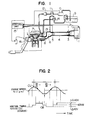
- Fig. 1 is a system diagram of the present invention
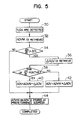
- Fig 2 is a characteristic diagram of engine speed (rpm) and ignition timing
- Fig. 3 is a block diagram illustrating an embodiment of the present invention
- Fig. 4 is a block diagram of an arrangement of a control unit
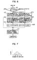
- Figs. 5 and 6 are respectively flowcharts of an embodiment of the present invention
- Fig. 7 is a graph of a relationship between the number of ignitions and the amount of correction
- Figs. 8, 9A and 9B are characteristic diagrams showing relationships between the engine speed and the ignition timing
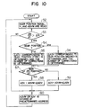
- Figs. 10, 11, 12, 15 and 16 are flowcharts of other embodiments of the present invention
- Fig. 13 is a characteristic diagram of an amount of correction with respect to a variation in revolution
- Fig. 14 is a graph for determining a correction area based on the engine speed and load.
- Fig. 1 air is introduced from an inlet portion 2 of an air cleaner 1, and passes through a hot wire type air flow meter 3 detecting sucked air volume, a duct 4, and a throttle body 5 having a throttle valve for controlling air flow, and enters into a collector 6.
- the air is distributed to each intake manifold 8 communicating directly with an internal combustion engine 7, and is sucked into a cylinder.
- fuel is sucked and pressured by a fuel pump 10 from a fuel tank 9, and is supplied to a fuel system including a fuel damper 11, a fuel filter 12, an injection valve 13 and a fuel regulator 14.
- the fuel is adjusted to a constant pressure by the fuel regulator 14, and is injected into the intake manifold 8 from the injection valve 13.
- a signal indicative of a detected amount of air sucked therein is outputted from the air flow meter 3, and this output signal is inputted to a control unit 15.
- a crank angle sensor 16a is built in a distributor 16, and outputs reference signals for fuel injection timing and ignition timing as well as a signal representing a detected engine speed, and these signals are supplied to the control unit 15.
- the control of the ignition timing in accordance with the present invention will be described in detail with reference to Figs. 2 and 3.
- the engine speed (rpm) is shown in the upper portion of the figure, and the behavior of the ignition timing is shown in the lower portion.
- the ignition timing is obtained by differentiating an amount of change in the engine speed (dN/dt) and by considering the sign of the dN/dt which indicates that when the engine speed is decreasing, the sign is negative and when it is increasing, the sign is positive.
- the stair-shaped curve representing the ignition timing shows that the ignition timing is retarded when the rate of change is larger than a predetermined value and the sign is positive, and the ignition timing is advanced when the sign is negative.
- an engine speed signal N detected by the crank angle sensor 16 is converted to a differentiated signal ⁇ in a differentiated value generating means 17.
- the differentiated signal ⁇ is supplied to a change rate discriminating means 18 for discriminating whether or not a change rate of the engine speed larger than a predetermined value ⁇ pre is caused or not, and is further supplied to a sign discriminating means 19 for discriminating a direction of change in the engine speed.
- a correction ignition timing amount ⁇ ADV is determined by a correction ignition timing amount determining means 20.
- a fundamental ignition amount ADVM is obtained in a fundamental ignition timing amount determining means 21 based on the engine speed signal N and an air volume signal Q a , correction ignition timing amount ⁇ ADV from the correction ignition timing amount determining means 20 and the fundamental ignition timing amount ADVM from the fundamental ignition amount determining means 21 are summed in a final ignition timing amount determining means 22 to produce a final ignition timing amount ADV.
- the control unit 15 is, as shown in Fig. 4, composed of an MPU, a RAM, a ROM, and an I/O device including an A/D converter and an input/output circuit.
- the control unit 15 performs predetermined computation and processing based on the output signal from the air flow meter 3 and the output signals from the crank angle sensor 16, etc., and an output signal of the control unit 15, representing the results of the computation is supplied to the fuel injection valve 13 to actuate so that a required amount of fuel is injected into each intake manifold 8. Further, it is designed to control the ignition timing by supplying a signal from the control unit 15 to a power transistor which controls a primary current of an ignition coil.
- a fundamental ignition timing amount ADVM determined by N and Q a is obtained.
- This fundamental ignition timing amount ADVM has been stored in the ROM as a map.
- the correction ignition timing amount ⁇ ADV is added to or subtracted from the fundamental ignition timing amount ADVM, and a final ignition timing amount ADV is obtained.
- the ignition timing amount ADVM or ADV determined in the steps 32, 40, and 42 is stored in a predetermined address in the RAM.
- the correction of the ignition timing is not carried out, and instead, at a portion at which the rate of change in the engine speed is large, the ignition timing is advanced if the engine speed is decreasing thereby to increase a torque, and the ignition timing is retarded when the engine speed is increasing thereby to decrease the torque.
- a satisfactory effect of suppressing the vibrations can be attained.
- the number of ignitions is counted from a time at which the differentiated value ⁇ is changed from a positive sign to a negative sign, or from the negative sign to the positive sign.
- Steps 48A and 48B are identical Steps 48A and 48B:
- a correction ignition timing amount ⁇ ADV is retrieved from a table in ROM.
- the correction ignition timing amount ⁇ ADV obtained in step 48A or 48B is added to or subtracted from the fundamental ignition timing amount ADVM to obtain a final ignition timing amount ADV.
- the fundamental ignition timing amount ADVM obtained in Step 32 and the final ignition timing amount ADV obtained in Step 49A or 49B are stored at predetermined addresses of the RAM.
- the ignition timing is corrected by using the correction amount and the number of corrections which are predetermined based on limited factors, even when the revolution period is changed.
- the vibration suppressing effect is further improved in another embodiment which will be explained hereinafter.
- the characteristic feature of this embodiment resides in that the number of corrections and the correction amount are changed in correspondence to a change in period of the revolution variation.
- Fig. 9A shows a change in the engine speed and ignition timing when a transmission is shifted to a first gear position
- Fig. 9B shows a change in the engine speed and ignition timing when the transmission is shifted to a second gear position.
- the period and amplitude of revolution variation differ between the first gear position and the second gear position, and there is a problem in that when the number of corrections and the amount of correction are determined uniformly, the surging is promoted, and irregular vibrations occur due to excessively large torque.
- a gear position signal and an actual engine speed N are read, and a fundamental ignition timing amount ADVM is read from a memory map.
- this step it is decided whether a change in the engine speed per a predetermined time dN/dt is larger than a predetermined engine speed change ⁇ N or not.
- a gear position is decided as to whether it is in a first position or in a second position.
- step 54 After the gear position has been decided in step 54, based on this decision, a correction ignition timing amount ⁇ ADV and a number of corrections are decided in correspondence with the gear position.
- this step it is decided whether a change in the engine speed is positive or negative. That is, a direction of change in the engine speed is decided.
- the correction amount ⁇ ADV obtained in steps 54 to 57 is added to or subtracted from the fundamental ignition timing amount ADVM.
- the final ignition timing amount ADV obtained in steps 58 and 59, or the fundamental ignition timing amount ADVM is stored at a predetermined address.
- the correction amount and the number of corrections may be changed, as shown in Fig. 11, using a predetermined changeover engine speed as a boundary.
- a predetermined changeover engine speed as a boundary.
- a correction amount ⁇ ADV and the number of corrections are determined in a similar manner as in the embodiment of Fig. 10.
- the correction ignition timing amount is changed from one value to the other in a manner as in switching operation depending on the gear position and the engine speed.
- the correction ignition timing amount is changed gradually.
- Step 62
- the engine speed N obtained in step 61 is differentiated, and it is decided whether a differentiated value dN/dt is larger than a predetermined value ⁇ N or not.
- step 62 When it is decided in step 62 that the engine speed is changing, the changing rate dN/dt is decided as to its magnitude, and a correction amount ⁇ ADV corresponding to the value is obtained from a memory map having a characteristic as shown in Fig. 13.
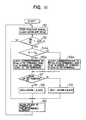
- step 64 When it is decided that the engine speed is in the increasing direction in step 64, the correction amount ⁇ ADV obtained in step 63 is subtracted from the fundamental ignition timing amount ADVM to obtain a final ignition timing amount ADV.
- Step 66
- the correction amount ⁇ ADV obtained in step 63 is added to the fundamental ignition timing amount ADVM to obtain a final ignition timing amount ADV.
- the fundamental ignition timing amount ADVM obtained in step 61, and the correction amount obtained in step 65 or 66 are stored at predetermined addresses, and actual ignition control is carried out.
- the modified embodiment it is designed to perform the aforementioned fundamental control only in a predetermined range of the engine speed.
- the ignition timing control is carried out in a range of the engine speed, that is above N1 and below N2.
- N1 corresponds to about 600 rpm and N2 corresponds to 1200 rpm, and a further condition is that a clutch is meeting.
- the reason for selecting N1 as 600 rpm is based on the findings in which at the time when the clutch meets, the engine speed decreases, and thus when the aforementioned fundamental control is carried out, it results in the control for advancing the ignition timing, and the output of the engine to cope with the load is decreased.
- the reason for selecting N2 as 1200 rpm is that the surging is essentially difficult to occur at the engine speed above 1200 rpm, and when the execution of the fundamental control is continued even at the engine speed above 1200 rpm a control time is needed for the microcomputer superfluously and the utilization efficiency is lowered.
- the correction area can be defined also by load.
- the load is obtained from a pulse width T p applied to the injection valve, and it is possible to determine that the control is carried out in a range wherein the load is smaller than a predetermined value T Pl .
- Step 68
- the engine speed N, load T p and fundamental ignition timing amount ADVM are read.
- Step 62
- step 62 When it is decided that a variation in the engine speed is equal to or larger than a predetermined value in step 62, it is decided in this step as to whether a correction of the ignition timing is really necessary or not.
- Fig. 14 The conditions for this decision are shown in Fig. 14 in that the ignition timing is corrected when the clutch is meeting and the engine speed N is in the range of N1 ⁇ N ⁇ N2, or further, the ignition timing is corrected when the load T P is smaller than the predetermined value T Pl .
- step 69 When it is decided that the operating parameters are in the correction area in step 69, the same processing as in step 63 in Fig. 12 is performed.
- Step 66
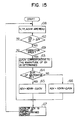
- the degree of suppression of vibrations due to surging in the engine differs depending on the load on the engine. In other words, even when the change in the engine speed is the same, and hence even when the same correction of the ignition timing is applied, the vibration suppressing effect differs depending on whether the transmission is at a neutral position or at any of the other positions. Thus, when the correction appropriate in the case of the neutral gear position is applied in other cases, the vibration suppressing effect is reduced.
- the gear position is read from a neutral switch, and further, an engine speed N at the present time and a fundamental ignition timing ADVM are read.
- Step 62
- a correction amount ⁇ ADV corresponding to a change in the engine speed dN is obtained from a characteristic curve G ON of the memory map in Fig. 13.
- a correction amount ⁇ ADV corresponding to the change in the engine speed dN is obtained from a characteristic curve G OFF in the memory map in Fig. 13.
- Step 66
- the gear position is decided whether it is at the neutral position or at any of the other positions, and depending on this decision, the correction amount is changed even when the change in the engine speed is the same. As a result, an optimum vibration suppressing effect can be obtained.
Landscapes
- Engineering & Computer Science (AREA)
- Mechanical Engineering (AREA)
- Chemical & Material Sciences (AREA)
- Combustion & Propulsion (AREA)
- General Engineering & Computer Science (AREA)
- Theoretical Computer Science (AREA)
- Signal Processing (AREA)
- Electrical Control Of Ignition Timing (AREA)
- Package Frames And Binding Bands (AREA)
- Table Devices Or Equipment (AREA)
- Gloves (AREA)
Claims (17)
- Verfahren zum Steuern des Zündzeitpunkts von Verbrennungskraftmaschinen, das die folgenden Schritte umfaßt:(a) Erfassen der Motordrehzahl (N),(b) Bestimmen der Motordrehzahländerungsgeschwindigkeit (dN/dt),(c) Unterscheiden, ob die Motordrehzahländerungsgeschwindigkeit (dN/dt) größer ist als ein vorbestimmter Wert,(d) Unterscheiden der Änderungsrichtung der Motordrehzahl (N) durch Bestimmen des Vorzeichens der Änderungsgeschwindigkeit (dN/dt),(e) Bestimmen eines Grundzündzeitpunktverstellbetrags (ADVM) auf der Basis von Betriebsbedingungen (N, Qa) des Motors,(f) Bestimmen eines Zündzeitpunktkorrekturbetrags (△ ADV) und(g) Bestimmen eines Endzündzeitpunktverstellbetrags (ADV) durch additives Korrigieren des Grundzündzeitpunktverstellbetrags (ADVM) durch den Zündzeitpunktkorrekturbetrag (△ ADV), wenn die Motordrehzahländerungsgeschwindigkeit (dN/dt) größer ist als der vorbestimmte Wert,dadurch gekennzeichnet, daß
der Zündzeitpunktkorrekturbetrag (△ ADV) derart auf der Basis des Ergebnisses der Unterscheidungsschritte c und d bestimmt wird, daß für eine vorbestimmte Anzahl von Zündungen nach einer Umkehrung des Vorzeichens des Änderungsgeschwindigkeitssignals (dN/dt) kein Zündzeitpunktkorrekturbetrag (△ ADV) angewandt wird, und ein Zündzeitpunktkorrekturbetrag (△ ADV) für eine vorbestimmte Anzahl von den nicht korrigierten Zündungen folgenden Zündungen angewandt wird, abhängig von der Anzahl der der Vorzeichenumkehr folgenden Zündungen. - Verfahren nach Anspruch 1,
dadurch gekennzeichnet, daß
unterschieden wird, ob sich der Motor in einer spezifischen Betriebsbedingung (N, Getriebeschaltstellung) befindet oder nicht und die Zündzeitpunktkorrekturbeträge (△ ADV) geändert werden, abhängig davon, ob sich der Motor in einer spezifischen Betriebsbedingung befindet oder nicht. - Verfahren nach Anspruch 1 und 2,
dadurch gekennzeichnet, daß
die Getriebeschaltstellung unterschieden wird und der Zündzeitpunktkorrekturbetrag (△ ADV) derart bestimmt wird, daß für eine niedrigere Getriebeschaltstellung der Zündzeitpunktkorrekturbetrag (△ ADV) größer wird. - Verfahren nach Anspruch 1 bis 3,
dadurch gekennzeichnet, daß
unterschieden wird, ob die Motordrehzahl (N) gleich oder größer ist als ein vorbestimmter Wert (Nn) oder nicht und der Zündzeitpunktkorrekturbetrag (△ ADV) derart bestimmt wird, daß mit einer höheren Motordrehzahl (N) der Zündzeitpunktkorrekturbetrag (△ ADV) größer wird. - Verfahren nach Anspruch 1 bis 4,
gekennzeichnet
dadurch, daß der Zündzeitpunktkorrekturbetrag (△ ADV) proportional zu der Motordrehzahländerungsgeschwindigkeit (dN/dt) bestimmt wird. - Verfahren nach Anspruch 1 bis 5,
dadurch gekennzeichnet, daß
erfaßt wird, ob die Motordrehzahl (N) innerhalb eines vorbestimmten Bereichs liegt, und die Bestimmung des Zündzeitpunktkorrekturbetrags (△ ADV) nur durchgeführt wird, wenn die Motordrehzahl (N) innerhalb des vorbestimmten Drehzahlbereichs liegt. - Verfahren nach Anspruch 6,
dadurch gekennzeichnet, daß
erfaßt wird, ob die Motorlast gleich oder kleiner als ein vorbestimmter Wert ist, und der Zündzeitpunktkorrekturbetrag (△ ADV) nur bestimmt wird, wenn die Last gleich oder kleiner als der vorbestimmte Wert ist und die Motordrehzahl (N) innerhalb des vorbestimmten Drehzahlbereichs liegt. - Verfahren nach Anspruch 1 bis 7,
dadurch gekennzeichnet, daß
erfaßt wird, ob das Getriebe in Leerlaufstellung ist oder nicht, und der Zündzeitpunktkorrekturbetrag (△ ADV) derart bestimmt wird, daß er für die Leerlaufstellung des Getriebes kleiner ist als für andere Getriebeschaltstellungen. - Verfahren nach Anspruch 1 bis 8,
dadurch gekennzeichnet, daß
der Zündzeitpunktkorrekturbetrag (△ ADV) derart bestimmt wird, daß er einen Maximalwert zu dem Zeitpunkt besitzt, an dem die Motordrehzahländerungsgeschwindigkeit (dN/dt) ein Maximum besitzt. - Vorrichtung zum Steuern des Zündzeitpunkts von Verbrennungskraftmaschinen, insbesondere zum Durchführen des Verfahrens nach Anspruch 1 bis 9, umfassend:(A) Motordrehzahlerfassungsmittel (16, 30, 52, 61, 68, 70) zum Erfassen der Motordrehzahl durch ein Motordrehzahlsignal (N)(B) Differentiationsmittel (17) zum Differenzieren des Motordrehzahlsignals (N) und zum Erzeugen eines dazu gehörigen Motordrehzahländerungsgeschwindigkeitssignals (dN/dt),(C) Änderungsgeschwindigkeitsunterscheidungsmittel (18, 34, 53, 62) zum Unterscheiden, ob das Motordrehzahländerungsgeschwindigkeitssignal (dN/dt) größer ist als ein vorbestimmter Wert,(D) Änderungsrichtungsunterscheidungsmittel (19, 38, 57, 64) zum Unterscheiden der Richtung der Änderung des Motordrehzahlsignals (N) durch Bestimmen des Vorzeichens des Änderungsgeschwindigkeitssignals (dN/dt),(E) Grundzündzeitpunktverstellbetrag-Bestimmungsmittel (21, 32) zum Bestimmen eines Grundzündzeitpunktverstellbetrags (ADVM) auf der Basis von Betriebsbedingungen (N, Qa) des Motors,(F) Zündzeitpunktkorrekturmittel (20) zum Bestimmen eines Zündzeitpunktkorrekturbetrags (△ ADV),
und(G) Endzündzeitpunktverstellbetrag-Bestimmungsmittel (22, 40, 42, 49A, 49B, 58, 59, 65, 66) zum Bestimmen eines Endzündzeitpunktverstellbetrags (ADV) durch additives Korrigieren des Grundzündzeitpunktverstellbetrags (ADVM) durch den Zündzeitpunktkorrekturbetrag(△ADV), wenn das Motordrehzahländerungsgeschwindigkeitssignal (dN/dt) größer ist als der durch die Änderungsgeschwindigkeitsunterscheidungsmittel (18, 34, 53, 62) bestimmte vorbestimmte Wert,dadurch gekennzeichnet, daß
die Zündzeitpunktkorrekturmittel (20, 36, 48A, 48B) derart ausgeführt sind, daß sie den Zündzeitpunktkorrekturbetrag (△ ADV) auf der Basis der durch die Änderungsgeschwindigkeitsunterscheidungsmittel (18, 34, 53, 62) und die Änderungsrichtungsunterscheidungsmittel (19, 38, 57,64) bestimmten Ergebnisse derart bestimmen, daß für eine vorbestimmte Anzahl von Zündungen nach der Umkehrung des Vorzeichens des Änderungsgeschwindigkeitssignals (dN/dt) kein Zündzeitpunktkorrekturbetrag (△ ADV) angewandt wird, und ein Zündzeitpunktkorrekturbetrag (△ ADV) für eine vorbestimmte Anzahl der nichtkorrigierten Zündungen folgenden Zündungen angewandt wird, abhängig von der Anzahl der der Vorzeichenumkehr folgenden Zündungen. - Vorrichtung nach Anspruch 10,
dadurch gekennzeichnet, daß
Bedingungsunterscheidungsmittel (54, 54A) vorgesehen sind, zum Bestimmen, ob der Motor in einer spezifischen Betriebsbedingung (N, Getriebeschaltstellung) ist oder nicht, und die Zündzeitpunktkorrekturmittel (20) derart ausgeführt sind, daß sie Zündzeitpunktkorrekturbeträge (△ ADV) bestimmen, die in Abhängigkeit davon, ob der Motor in einer spezifischen Betriebsbedingung ist oder nicht, unterschiedlich sind. - Vorrichtung nach Anspruch 11,
dadurch gekennzeichnet, daß
die Bedingungsunterscheidungsmittel (54) die Getriebeschaltstellung unterscheiden und die Zündzeitpunktkorrekturmittel (20) den Zündzeitpunktkorrekturbetrag (△ ADV) derart bestimmen, daß für eine niedrigere Getriebeschaltstellung der Zündzeitpunktkorrekturbetrag (△ ADV) größer wird. - Vorrichtung nach Anspruch 11,
dadurch gekennzeichnet, daß
die Bedingungsunterscheidungsmittel (54A) unterscheiden, ob die Motordrehzahl (N) gleich oder größer als ein vorbestimmter Wert (Nn) ist oder nicht, und die Zündzeitpunktkorrekturmittel (20) den Zündzeitpunktkorrekturbetrag (△ ADV) derart bestimmen, daß mit einer höheren Motordrehzahl (N) der Zündzeitpunktkorrekturbetrag (△ ADV) größer wird. - Vorrichtung nach Anspruch 10 bis 13,
dadurch gekennzeichnet, daß
die Zündzeitpunktkorrekturmittel (20) derart ausgeführt sind, daß der Zündzeitpunktkorrekturbetrag (△ ADV) proportional zu der Motordrehzahländerungsgeschwindigkeit (dN/dt) bestimmt wird. - Vorrichtung nach Anspruch 10 bis 14,
dadurch gekennzeichnet, daß
sie Geschwindigkeitsbereichserfassungsmittel (69) enthält zum Erfassen, daß die Motordrehzahl (N) innerhalb eines vorbestimmten Bereichs liegt, und die Zündzeitpunktkorrekturmittel (20) derart ausgeführt sind, daß ein Zündzeitpunktkorrekturbetrag (△ ADV) nur dann bestimmt wird, wenn die Motordrehzahl (N) innerhalb des vorbestimmten Drehzahlbereichs liegt. - Vorrichtung nach Anspruch 15,
dadurch gekennzeichnet, daß
sie Lasterfassungsmittel (Fig. 14) enthält, zum Erfassen, daß die Motorlast gleich oder kleiner als ein vorbestimmter Wert ist, und die Zündzeitpunktkorrekturmittel (20) derart ausgeführt sind, daß ein Zündzeitpunktkorrekturbetrag (△ ADV) nur bestimmt wird, wenn die Last gleich oder kleiner als der vorbestimmte Wert ist und die Motordrehzahl (N) innerhalb des vorbestimmten Drehzahlbereichs liegt. - Vorrichtung nach Anspruch 10 bis 16,
dadurch gekennzeichnet, daß
sie Leerlauferfassungsmittel (71) enthält, zum Erfassen, ob das Getriebe in Leerlaufstellung ist oder nicht, und die Zündzeitpunktkorrekturmittel (20) derart ausgeführt sind, daß der Zündzeitpunktkorrekturbetrag (△ ADV) für die Leerlaufstellung des Getriebes kleiner ist als für andere Getriebeschaltstellungen.
Applications Claiming Priority (2)
| Application Number | Priority Date | Filing Date | Title |
|---|---|---|---|
| JP614/86 | 1986-01-08 | ||
| JP61000614A JP2511862B2 (ja) | 1986-01-08 | 1986-01-08 | 内燃機関の点火時期制御方法 |
Publications (2)
| Publication Number | Publication Date |
|---|---|
| EP0233449A1 EP0233449A1 (de) | 1987-08-26 |
| EP0233449B1 true EP0233449B1 (de) | 1991-06-12 |
Family
ID=11478610
Family Applications (1)
| Application Number | Title | Priority Date | Filing Date |
|---|---|---|---|
| EP87100095A Expired - Lifetime EP0233449B1 (de) | 1986-01-08 | 1987-01-07 | Steuerverfahren und Anlage für den Zündzeitpunkt von Brennkraftmaschinen |
Country Status (5)
| Country | Link |
|---|---|
| US (1) | US4799469A (de) |
| EP (1) | EP0233449B1 (de) |
| JP (1) | JP2511862B2 (de) |
| KR (2) | KR870007358A (de) |
| DE (1) | DE3770652D1 (de) |
Families Citing this family (35)
| Publication number | Priority date | Publication date | Assignee | Title |
|---|---|---|---|---|
| US4843556A (en) * | 1985-07-23 | 1989-06-27 | Lucas Industries Public Limited Company | Method and apparatus for controlling an internal combustion engine |
| GB8700759D0 (en) * | 1987-01-14 | 1987-02-18 | Lucas Ind Plc | Adaptive control system |
| DE3871832T2 (de) * | 1987-03-25 | 1993-01-14 | Japan Electronic Control Syst | Vorrichtung zur zuendsteuerung und zur unterdrueckung von stoerschwingungen waehrend des beschleunigens einer brennkraftmaschine. |
| GB8715130D0 (en) * | 1987-06-27 | 1987-08-05 | Lucas Ind Plc | Adaptive control system for i c engine |
| GB8721688D0 (en) * | 1987-09-15 | 1987-10-21 | Lucas Ind Plc | Adaptive control system |
| JPH01100379A (ja) * | 1987-10-09 | 1989-04-18 | Daihatsu Motor Co Ltd | エンジンのサージ防止方法 |
| JP2646216B2 (ja) * | 1987-10-29 | 1997-08-27 | 三信工業株式会社 | 2サイクル内燃機関の点火時期制御装置 |
| JP2701270B2 (ja) * | 1987-11-05 | 1998-01-21 | 株式会社日立製作所 | 点火進角制御装置 |
| JP2585312B2 (ja) * | 1987-11-09 | 1997-02-26 | 日産自動車株式会社 | 内燃機関の点火時期制御装置 |
| US4945875A (en) * | 1988-03-07 | 1990-08-07 | Mitsubishi Denki Kabushiki Kaisha | Electronic ignition timing control device |
| US5090384A (en) * | 1988-03-25 | 1992-02-25 | Robert Bosch Gmbh | Electronic control device for modulating fuel quantities in an internal combustion engine |
| JPH086667B2 (ja) * | 1988-04-15 | 1996-01-29 | 株式会社日立製作所 | 内燃機関の点火時期制御装置 |
| US5021956A (en) * | 1988-04-25 | 1991-06-04 | Mazda Motor Corporation | Control systems for vehicle engines coupled with automatic transmissions |
| GB8810878D0 (en) * | 1988-05-07 | 1988-06-08 | Lucas Ind Plc | Adaptive control system for i c engine |
| JPH0223268A (ja) * | 1988-07-13 | 1990-01-25 | Toyota Motor Corp | 内燃機関用点火時期制御装置 |
| JPH0814271B2 (ja) * | 1988-09-12 | 1996-02-14 | 日産自動車株式会社 | 内燃機関の点火時期制御装置 |
| EP0372102B2 (de) * | 1988-12-02 | 1995-11-29 | Siemens Aktiengesellschaft | Verfahren zur Steuerung des Zündwinkels einer Brennkraftmaschine |
| JP2544472B2 (ja) * | 1989-03-01 | 1996-10-16 | 株式会社日立製作所 | 多気筒エンジン用燃焼制御装置 |
| JP3085382B2 (ja) * | 1989-08-25 | 2000-09-04 | 株式会社日立製作所 | 内燃機関の燃焼状態制御方法 |
| DE4011386A1 (de) * | 1990-04-07 | 1991-10-10 | Bosch Gmbh Robert | Verfahren zur zuendwinkelverstellung bei lastaenderungen |
| US5452698A (en) * | 1990-05-07 | 1995-09-26 | Robert Bosch Gmbh | Device for suppressing discontinuous motion of a moving motor vehicle |
| FR2678986A1 (fr) * | 1991-07-09 | 1993-01-15 | Siemens Automotive Sa | Procede de correction en regime transitoire de l'avance a l'allumage d'un moteur a combustion interne et son application au lissage des a-coups du regime du moteur. |
| FR2680203B1 (fr) * | 1991-08-06 | 1993-11-05 | Siemens Automotive Sa | Procede de lissage d'a-coups d'acceleration d'un vehicule propulse par un moteur a combustion interne. |
| JP2833935B2 (ja) * | 1992-07-10 | 1998-12-09 | 三菱電機株式会社 | 内燃機関制御装置 |
| DE4232204C2 (de) * | 1992-09-25 | 1995-11-02 | Siemens Ag | Verfahren zur Unterdrückung von Schwingungen im Antriebsstrang eines Kraftfahrzeugs |
| FR2713286B1 (fr) * | 1993-11-30 | 1996-01-05 | Renault | Procédé de correction des à-coups de couple d'un moteur à combustion interne. |
| US5701865A (en) * | 1996-04-26 | 1997-12-30 | Chrysler Corporation | Method of adjusting idle spark for an individual cylinder of an internal combustion engine |
| US6892702B2 (en) * | 2000-10-12 | 2005-05-17 | Kabushiki Kaisha Moric | Ignition controller |
| JP2002202038A (ja) * | 2001-01-09 | 2002-07-19 | Honda Motor Co Ltd | エンジンの点火時期制御装置 |
| US20030015175A1 (en) * | 2001-07-18 | 2003-01-23 | Andersson Martin N. | Ignition timing control system for light duty combustion engines |
| US7198028B2 (en) * | 2001-07-18 | 2007-04-03 | Walbro Engine Management, L.L.C. | Ignition timing control system for light duty combustion engines |
| US6814053B2 (en) * | 2002-11-06 | 2004-11-09 | Detroit Diesel Corporation | Method and apparatus for limiting engine operation in a programmable range |
| CN101213368A (zh) * | 2005-07-01 | 2008-07-02 | 百佳车辆有限公司 | 用于控制发动机噪声的方法及系统 |
| GB0705024D0 (en) * | 2007-03-15 | 2007-04-25 | Delphi Tech Inc | Vehicle diagnosis device and method |
| JP6621787B2 (ja) * | 2017-10-19 | 2019-12-18 | 本田技研工業株式会社 | 内燃機関の点火時期制御装置 |
Family Cites Families (14)
| Publication number | Priority date | Publication date | Assignee | Title |
|---|---|---|---|---|
| FR1377282A (fr) * | 1963-03-07 | 1964-11-06 | Renault | Procédé et dispositif pour obtenir par variation d'avance la décélération du moteur d'un véhicule automobile muni d'une boîte de vitesse automatique |
| DE2961307D1 (en) * | 1978-08-09 | 1982-01-14 | Bosch Gmbh Robert | Ignition and fuel injection control system for internal combustion engines |
| US4276860A (en) * | 1979-11-01 | 1981-07-07 | Motorola, Inc. | Apparatus for the generation of monostable pulses having predetermined durations independent of input signal period |
| JPS56113049A (en) * | 1980-02-12 | 1981-09-05 | Nissan Motor Co Ltd | Ignition timing control method |
| FR2477236B1 (fr) * | 1980-03-03 | 1987-04-17 | Mitsubishi Electric Corp | Systeme de commande du point d'allumage pour un moteur a combustion interne |
| JPS5738642A (en) * | 1980-08-19 | 1982-03-03 | Nippon Denso Co Ltd | Method of internal-combustion engine control |
| JPS57143161A (en) * | 1981-03-02 | 1982-09-04 | Nippon Denso Co Ltd | Ignition time controlling method for internal combustion engine |
| JPS5848738A (ja) * | 1981-09-16 | 1983-03-22 | Toyota Motor Corp | 車両の振動抑制制御装置 |
| US4424783A (en) * | 1981-11-11 | 1984-01-10 | General Motors Corporation | Combustion chamber inlet temperature corrected combustion initiation timing |
| FR2531145B1 (fr) * | 1982-07-27 | 1987-04-30 | Marchal Equip Auto | Procede de regulation auto-adaptative de l'angle d'avance a l'allumage d'un moteur thermique a allumage commande |
| DE3242483A1 (de) * | 1982-11-18 | 1984-05-24 | Vdo Adolf Schindling Ag, 6000 Frankfurt | Elektrische vorrichtung zum beseitigen des ruckelns von fahrzeugen |
| DE3243235A1 (de) * | 1982-11-23 | 1984-05-24 | Robert Bosch Gmbh, 7000 Stuttgart | Einrichtung zum daempfen von ruckelschwingungen bei einer brennkraftmaschine in einem kraftfahrzeug |
| JPS606071A (ja) * | 1983-06-24 | 1985-01-12 | Toyota Motor Corp | 車両用エンジンの点火時期制御装置 |
| JPS6259741U (de) * | 1985-10-03 | 1987-04-14 |
-
1986
- 1986-01-08 JP JP61000614A patent/JP2511862B2/ja not_active Expired - Lifetime
-
1987
- 1987-01-05 US US07/000,446 patent/US4799469A/en not_active Expired - Lifetime
- 1987-01-06 KR KR870000027A patent/KR870007358A/ko active Granted
- 1987-01-07 DE DE8787100095T patent/DE3770652D1/de not_active Expired - Lifetime
- 1987-01-07 EP EP87100095A patent/EP0233449B1/de not_active Expired - Lifetime
-
1988
- 1988-01-06 KR KR1019870000027A patent/KR930009908B1/ko not_active Expired - Fee Related
Also Published As
| Publication number | Publication date |
|---|---|
| DE3770652D1 (de) | 1991-07-18 |
| JPS62159771A (ja) | 1987-07-15 |
| KR870007358A (ko) | 1987-08-18 |
| KR890011761A (ko) | 1989-08-22 |
| KR930009908B1 (ko) | 1993-10-13 |
| JP2511862B2 (ja) | 1996-07-03 |
| EP0233449A1 (de) | 1987-08-26 |
| US4799469A (en) | 1989-01-24 |
Similar Documents
| Publication | Publication Date | Title |
|---|---|---|
| EP0233449B1 (de) | Steuerverfahren und Anlage für den Zündzeitpunkt von Brennkraftmaschinen | |
| US4852537A (en) | Ignition timing control apparatus for internal combustion engine | |
| US4596217A (en) | Method and system to prevent knocking operation of an internal combustion engine | |
| US4582032A (en) | Ignition timing control system for internal combustion engine | |
| US4509331A (en) | Knock-free engine control system for turbocharged automotive engine | |
| KR100679475B1 (ko) | 내연기관의 노킹 억제 방법 | |
| US4425890A (en) | Spark timing control apparatus for use with a internal combustion engine | |
| US4446832A (en) | Method and system for controlling the idle speed of an internal combustion engine at variable ignition timing | |
| US4636957A (en) | Method for controlling operating state of an internal combustion engine with an overshoot preventing function | |
| EP0921296B1 (de) | Kraftstoffeinspritzsteuerungsvorrichtung für eine Brennkraftmaschine | |
| EP0345814B1 (de) | Elektrisches Steuergerät für Kraftfahrzeug und Kompensationsverfahren der Zeitverzögerung von Messdaten | |
| JPH07208309A (ja) | 内燃機関制御方法及び装置 | |
| US5174259A (en) | Fuel injection control system for turbocharged diesel engine | |
| KR100317158B1 (ko) | 내연기관의아이들링속도제어시스템 | |
| EP0337491B1 (de) | Verfahren und Vorrichtung zur Steuerung vom Zündzeitpunkt bei Brennkraftmaschinen | |
| US4367711A (en) | Method and apparatus for ignition system spark timing control within warm-up period of the engine | |
| US4370968A (en) | Electronically controlled, fuel injection method | |
| EP0216291B2 (de) | Verfahren zur Steuerung einer Brennkraftmaschine | |
| EP0098584B2 (de) | Zündzeitpunktsteuerverfahren für Brennkraftmaschine | |
| EP0347756A2 (de) | Steuereinrichtung für einen Turbolader bei einem Verbrennungsmotor | |
| EP0980972B1 (de) | Kraftstoffeinspritzsteuervorrichtung und -Verfahren für eine Brennkraftmaschine | |
| US4909217A (en) | Electronic-type engine control method | |
| EP0196657B1 (de) | Elektronisches Kraftstoffeinspritzverfahren und entsprechende Vorrichtung für eine Brennkraftmaschine | |
| US4785779A (en) | Internal combustion engine control apparatus | |
| US5295466A (en) | Knock suppression apparatus for an internal combustion engine |
Legal Events
| Date | Code | Title | Description |
|---|---|---|---|
| PUAI | Public reference made under article 153(3) epc to a published international application that has entered the european phase |
Free format text: ORIGINAL CODE: 0009012 |
|
| AK | Designated contracting states |
Kind code of ref document: A1 Designated state(s): DE GB |
|
| 17P | Request for examination filed |
Effective date: 19870828 |
|
| 17Q | First examination report despatched |
Effective date: 19890602 |
|
| GRAA | (expected) grant |
Free format text: ORIGINAL CODE: 0009210 |
|
| AK | Designated contracting states |
Kind code of ref document: B1 Designated state(s): DE GB |
|
| REF | Corresponds to: |
Ref document number: 3770652 Country of ref document: DE Date of ref document: 19910718 |
|
| PLBE | No opposition filed within time limit |
Free format text: ORIGINAL CODE: 0009261 |
|
| STAA | Information on the status of an ep patent application or granted ep patent |
Free format text: STATUS: NO OPPOSITION FILED WITHIN TIME LIMIT |
|
| 26N | No opposition filed | ||
| REG | Reference to a national code |
Ref country code: GB Ref legal event code: IF02 |
|
| PGFP | Annual fee paid to national office [announced via postgrant information from national office to epo] |
Ref country code: GB Payment date: 20020107 Year of fee payment: 16 |
|
| PGFP | Annual fee paid to national office [announced via postgrant information from national office to epo] |
Ref country code: DE Payment date: 20020328 Year of fee payment: 16 |
|
| PG25 | Lapsed in a contracting state [announced via postgrant information from national office to epo] |
Ref country code: GB Free format text: LAPSE BECAUSE OF NON-PAYMENT OF DUE FEES Effective date: 20030107 |
|
| PG25 | Lapsed in a contracting state [announced via postgrant information from national office to epo] |
Ref country code: DE Free format text: LAPSE BECAUSE OF NON-PAYMENT OF DUE FEES Effective date: 20030801 |
|
| GBPC | Gb: european patent ceased through non-payment of renewal fee |
Effective date: 20030107 |