EP0233458A1 - Borne de raccordement pour câble de protection - Google Patents
Borne de raccordement pour câble de protection Download PDFInfo
- Publication number
- EP0233458A1 EP0233458A1 EP87100194A EP87100194A EP0233458A1 EP 0233458 A1 EP0233458 A1 EP 0233458A1 EP 87100194 A EP87100194 A EP 87100194A EP 87100194 A EP87100194 A EP 87100194A EP 0233458 A1 EP0233458 A1 EP 0233458A1
- Authority
- EP
- European Patent Office
- Prior art keywords
- rail
- compression spring
- foot
- recess
- edge
- Prior art date
- Legal status (The legal status is an assumption and is not a legal conclusion. Google has not performed a legal analysis and makes no representation as to the accuracy of the status listed.)
- Granted
Links
- 230000006835 compression Effects 0.000 claims abstract description 46
- 238000007906 compression Methods 0.000 claims abstract description 46
- 230000001681 protective effect Effects 0.000 claims abstract description 28
- 239000004020 conductor Substances 0.000 claims description 27
- 230000000694 effects Effects 0.000 description 1
- 230000007704 transition Effects 0.000 description 1
- 230000000007 visual effect Effects 0.000 description 1
Images
Classifications
-
- H—ELECTRICITY
- H01—ELECTRIC ELEMENTS
- H01R—ELECTRICALLY-CONDUCTIVE CONNECTIONS; STRUCTURAL ASSOCIATIONS OF A PLURALITY OF MUTUALLY-INSULATED ELECTRICAL CONNECTING ELEMENTS; COUPLING DEVICES; CURRENT COLLECTORS
- H01R9/00—Structural associations of a plurality of mutually-insulated electrical connecting elements, e.g. terminal strips or terminal blocks; Terminals or binding posts mounted upon a base or in a case; Bases therefor
- H01R9/22—Bases, e.g. strip, block, panel
- H01R9/24—Terminal blocks
- H01R9/26—Clip-on terminal blocks for side-by-side rail- or strip-mounting
- H01R9/2691—Clip-on terminal blocks for side-by-side rail- or strip-mounting with ground wire connection to the rail
Definitions
- the invention relates to a protective conductor terminal, in particular in a terminal block housing, the foot of which serves as a tension bracket and has supports in a deep and in a shallow recess for support on hat-shaped support rails in cross section and holds a compression spring which springs with sliding zones against the recesses and when Put on a mounting rail to make contact.
- a protective conductor terminal is the subject of a patent application with older seniority (DE: P 35 26 494.2).
- the compression spring has a rounded end on a rail edge in the deep recess.
- An external additional spring which is integrally formed on the housing, is laterally in the deep recess against the rail edge of an inserted mounting rail and presses the housing away from it, so that the flat recess can grip around the other rail edge, whereby the clamp is fastened to the mounting rail.
- the compression spring is shaped in the transition to its end on the flat recess in such a way that a sliding zone is formed against the inner edge of a support rail which is hat-shaped in cross section, so that the compression spring slides in a wedge shape against the edge of the rail and rubs off insulating dirt or oxide layers. This ensures good electrical contact.
- An electrical terminal block is known, which is designed as a protective conductor terminal (DE-PS 31 26 535), in which a pressure bracket, under the force of the clamping screw of an electrical connection terminal, presses against a rail edge of a mounting rail inserted into the recesses of the tension bracket.
- the electrical contact should be achieved by teeth in the support of the associated recess for the rail edge in the drawbar.
- the protective conductor connecting terminal initially does not find a secure hold when it is placed on the mounting rail, which disturbs during assembly. With the protective conductor connection terminal with older seniority, a secure hold on the mounting rail is achieved regardless of the clamping screw, but an additional spring is used for this.
- the invention has for its object to develop a protective conductor terminal that finds a secure hold already when it is placed on the mounting rail, but does with a single compression spring.
- the solution of the described task is according to the invention is that the compression spring due to its shape with respect to the recesses in the foot and with respect to abutments on the foot when placing the foot with the deep recess on a mounting rail its tensioning and moving the foot to reach around the rail edge caused by the flat recess by a force component parallel to the rail plane.
- the slide-on zones are aligned here in such a way that the compressive force of the tensioned compression spring has a component which is directed parallel to the rail plane to the flat recess and in opposition to the rail pulls the foot with the flat recess onto the rail edge.
- the sliding movement on the slide-on zone also allows dirt or oxide layers to be rubbed off, so that electrical contact is ensured.
- the protective conductor terminal can generate the forces for transferring your foot into a secure hold on the mounting rail according to claim 2 only at the deep recess, according to claim 3 solely by the sliding zone on the flat recess or according to claim 4 by mutual support.
- the deep recess in the foot of the protective conductor connection terminal enables an oblique placement on a mounting rail according to the shape and inclination of the support for the rail edge, the placement and removal is facilitated. On the other hand, this also gives a visual indication of which terminal is attached and which terminal is only loosely attached.
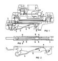
- a protective conductor terminal is illustrated, the foot of which is designed according to the invention.
- the protective conductor connection terminal 1 has a foot 2, which forms a pull bracket for attachment to a mounting rail.
- he has in a deep recess 3 and in a flat recess 4 supports for support on hat-shaped support rails 5 - according to FIG. If you put the protective conductor terminal 1 on a mounting rail, it is tensioned, which also ensures electrical contact.
- 1 is in the exemplary embodiment part of a terminal block with further connection levels 9 and 10.
- the compression spring 6 is tensioned by its shape with respect to the recesses 3, 4 in the foot 2 and with respect to abutments 11, 12 on the foot 2 when the foot with the deep recess 3 is placed on a mounting rail. Under the force of the tensioned compression spring, the foot 2 is then shifted until the flat recess 4 is gripped around the rail edge. This causes a force component of the spring in each case parallel to the rail plane in counteraction with the rail.
- the compression spring 6 As a holder for the compression spring 6 13 in a flank U-shaped bent foot 2 according to FIGS. 2 and 3 in its flanks 13 14 excluded. Lugs 15 of the compression spring 6 engage in this, with play being left so that the compression spring 6 remains somewhat displaceable in the longitudinal direction in the foot 2.
- the compression spring 6 is formed from round wire, which is bent at one end and returned over the entire length of the spring, as can be seen from FIG. 3.
- the spring jet not only has the advantage of strong compressive forces, but also low friction and good contact, since the compression spring rubs dirt and oxide layers in a narrow channel when it slides on a mounting rail.
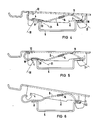
- Fig. 4 it is illustrated how a protective conductor terminal with two sliding zones 7 and 8, with its foot 2 is placed on a mounting rail 5.
- a mounting rail edge is inserted into the deep recess 3.
- the compression spring 6 is supported between its holder, window 14, in the foot and the deep recess 3 against an abutment 11 on the foot. With its rounded end, it engages in the deep recess 3, the apex 16 still lying outside the rail edge when the position is raised by the rail thickness.
- the compression spring 6 is at the rail edge in an imaginary sliding plane 17.
- a horizontal component of the spring force oriented with reference to the drawing acts, which pushes the foot 2 against the rail edge and thereby pulls the flat recess 4 onto the other rail edge.
- the compression spring 6 When the compression spring 6 is tensioned, it changes from a position according to FIG. 2 into a position according to FIG. 4.
- the other rail edge slides along the slope 18 of the foot in the flat recess. 5 is snapped onto the mounting rail, the end of the compression spring 6 is supported against an abutment 12 on the foot.
- This abutment is seen in the longitudinal direction of the foot near the support 19 of the compression spring 6 on the rail edge in order to form a hard spring for the terminal seat and for making contact.
- the compression spring is then raised by the rail thickness.
- the compression spring 6 can be supported at least shortly before against the abutment 12 in order to increase the spring force.
- the compression spring 6 between the flat recess 4 and the position of the adjacent inner rail edge 20 of an inserted mounting rail has a sliding zone 8 according to the exemplary embodiment in a sliding plane 21 which runs obliquely to the rail edge, as shown in FIG. 4, the foot can thereby be connected to the flat recess 4 Carrier rail can be snapped on.
- This slide zone on the shallow recess supports the effect of the slide zone on the deep recess.
- the end of the compression spring 6 between the support 19 according to FIG. 5 at the rail edge and the abutment 12 at the base 2 provides essential holding forces for the protective conductor connection clamp when it is snapped onto a mounting rail.
- the compression spring 6 conveys further holding forces with its other end depending on the length between the abutment 9 at the base 2 and the support in the sliding plane 17 on the rail edge, in connection with the clamping point in the window 14.
- the forces which ensure that the Feet with its shallow recess 4 on the rail edge provide the slide levels 17 and 21. It is sufficient if one of the slide levels 17 and 21 can be effective. These can support each other in the case of two sliding levels.
- the deep recess 3 in the foot 2 enables an oblique placement on the mounting rail by the shape and / or inclination of the support 22 for the rail edge. This position can be achieved in particular if the foot 2 is released from the mounting rail 5 by lateral pressure on the rail edge at the deep recess 3. If a slide zone 8 is formed on the compression spring 6 in front of its opposite end, the inclined position of the foot according to FIG. 6 can also be allowed for assembly, since the slide zone 8 then ensures that the foot 2 is securely pulled up and held during assembly.
Landscapes
- Connections Arranged To Contact A Plurality Of Conductors (AREA)
- Insulated Conductors (AREA)
- Non-Insulated Conductors (AREA)
- Coupling Device And Connection With Printed Circuit (AREA)
- Cable Accessories (AREA)
Priority Applications (1)
| Application Number | Priority Date | Filing Date | Title |
|---|---|---|---|
| AT87100194T ATE64798T1 (de) | 1986-01-23 | 1987-01-09 | Schutzleiteranschlussklemme. |
Applications Claiming Priority (2)
| Application Number | Priority Date | Filing Date | Title |
|---|---|---|---|
| DE3602003 | 1986-01-23 | ||
| DE3602003 | 1986-01-23 |
Publications (2)
| Publication Number | Publication Date |
|---|---|
| EP0233458A1 true EP0233458A1 (fr) | 1987-08-26 |
| EP0233458B1 EP0233458B1 (fr) | 1991-06-26 |
Family
ID=6292480
Family Applications (1)
| Application Number | Title | Priority Date | Filing Date |
|---|---|---|---|
| EP87100194A Expired - Lifetime EP0233458B1 (fr) | 1986-01-23 | 1987-01-09 | Borne de raccordement pour câble de protection |
Country Status (4)
| Country | Link |
|---|---|
| EP (1) | EP0233458B1 (fr) |
| AT (1) | ATE64798T1 (fr) |
| AU (1) | AU600465B2 (fr) |
| DE (1) | DE3770949D1 (fr) |
Cited By (10)
| Publication number | Priority date | Publication date | Assignee | Title |
|---|---|---|---|---|
| DE4203184A1 (de) * | 1992-02-05 | 1993-08-12 | Weidmueller Interface | Schutzleiterklemme |
| EP0597191A1 (fr) * | 1992-11-09 | 1994-05-18 | Weidmüller Interface GmbH & Co. | Borne pour conducteur de protection |
| FR2786941A1 (fr) * | 1998-12-02 | 2000-06-09 | Patrick Bourgin | Dispositif de raccordement a la masse d'une borne d'un appareil electrique |
| FR2803440A1 (fr) * | 2000-01-04 | 2001-07-06 | Entrelec Sa | Ressort de fixation d'un bloc de jonction ou similaire sur un rail |
| DE19960838A1 (de) * | 1999-12-16 | 2001-07-19 | Siemens Ag | Schutzleiteranschlußklemme |
| EP1191643A3 (fr) * | 2000-09-25 | 2002-11-13 | PHOENIX CONTACT GmbH & Co. Kg | Boítier pour un dispositif électronique |
| EP1182735A3 (fr) * | 2000-08-22 | 2003-11-05 | Phoenix Contact GmbH & Co. KG | Réglette d'interconnexion électrique |
| EP1860738A1 (fr) | 2006-05-22 | 2007-11-28 | Legrand France | Bloc de jonction pour conducteurs électriques |
| WO2015090729A1 (fr) * | 2013-12-18 | 2015-06-25 | Phoenix Contact Gmbh & Co. Kg | Élément métallique de connexion de conducteur de terre et bloc de jonction électrique |
| WO2017102764A1 (fr) * | 2015-12-17 | 2017-06-22 | Te Connectivity Germany Gmbh | Prise de rail à transmission de courant améliorée |
Families Citing this family (4)
| Publication number | Priority date | Publication date | Assignee | Title |
|---|---|---|---|---|
| DE3903752A1 (de) * | 1989-02-06 | 1990-08-09 | Wago Verwaltungs Gmbh | Schutzleiter-reihenklemme |
| FR2659118B1 (fr) * | 1990-03-02 | 1992-05-07 | Entrelec Sa | Dispositif de fixation d'un bloc de jonction sur un profile support symetrique. |
| EP0751585B1 (fr) | 1995-06-28 | 2000-01-19 | Siemens Aktiengesellschaft | Butée d'arrêt pour barrettes de raccordement |
| DE19708912C1 (de) * | 1997-03-05 | 1998-06-10 | Weidmueller Interface | Schutzleiteranschlußklemme, insbesondere in einem Reihenklemmengehäuse |
Citations (2)
| Publication number | Priority date | Publication date | Assignee | Title |
|---|---|---|---|---|
| DE1070719B (fr) * | 1959-12-10 | |||
| GB927219A (en) * | 1959-03-11 | 1963-05-29 | Charlotte Glasel | Improvements in housings or bodies for electrical terminal block units or series connectors |
Family Cites Families (1)
| Publication number | Priority date | Publication date | Assignee | Title |
|---|---|---|---|---|
| GB1436707A (en) * | 1972-07-21 | 1976-05-26 | Rotaflex Ltd | Electrical supply installations |
-
1987
- 1987-01-09 EP EP87100194A patent/EP0233458B1/fr not_active Expired - Lifetime
- 1987-01-09 DE DE8787100194T patent/DE3770949D1/de not_active Expired - Lifetime
- 1987-01-09 AT AT87100194T patent/ATE64798T1/de active
- 1987-01-22 AU AU67910/87A patent/AU600465B2/en not_active Ceased
Patent Citations (2)
| Publication number | Priority date | Publication date | Assignee | Title |
|---|---|---|---|---|
| DE1070719B (fr) * | 1959-12-10 | |||
| GB927219A (en) * | 1959-03-11 | 1963-05-29 | Charlotte Glasel | Improvements in housings or bodies for electrical terminal block units or series connectors |
Cited By (14)
| Publication number | Priority date | Publication date | Assignee | Title |
|---|---|---|---|---|
| DE4203184A1 (de) * | 1992-02-05 | 1993-08-12 | Weidmueller Interface | Schutzleiterklemme |
| EP0597191A1 (fr) * | 1992-11-09 | 1994-05-18 | Weidmüller Interface GmbH & Co. | Borne pour conducteur de protection |
| FR2786941A1 (fr) * | 1998-12-02 | 2000-06-09 | Patrick Bourgin | Dispositif de raccordement a la masse d'une borne d'un appareil electrique |
| DE19960838A1 (de) * | 1999-12-16 | 2001-07-19 | Siemens Ag | Schutzleiteranschlußklemme |
| FR2803440A1 (fr) * | 2000-01-04 | 2001-07-06 | Entrelec Sa | Ressort de fixation d'un bloc de jonction ou similaire sur un rail |
| DE10100182B4 (de) * | 2000-01-04 | 2006-12-14 | Entrelec Sa | Feder zur Befestigung einer Reihenklemme an einer Schiene |
| EP1182735A3 (fr) * | 2000-08-22 | 2003-11-05 | Phoenix Contact GmbH & Co. KG | Réglette d'interconnexion électrique |
| EP1191643A3 (fr) * | 2000-09-25 | 2002-11-13 | PHOENIX CONTACT GmbH & Co. Kg | Boítier pour un dispositif électronique |
| EP1860738A1 (fr) | 2006-05-22 | 2007-11-28 | Legrand France | Bloc de jonction pour conducteurs électriques |
| WO2015090729A1 (fr) * | 2013-12-18 | 2015-06-25 | Phoenix Contact Gmbh & Co. Kg | Élément métallique de connexion de conducteur de terre et bloc de jonction électrique |
| CN105830282A (zh) * | 2013-12-18 | 2016-08-03 | 菲尼克斯电气公司 | 金属的保护导体连接元件及电气端子板 |
| US9831569B2 (en) | 2013-12-18 | 2017-11-28 | Phoenix Contact Gmbh & Co. Kg | Metal protective conductor connection element and electrical series terminal |
| CN105830282B (zh) * | 2013-12-18 | 2019-04-16 | 菲尼克斯电气公司 | 金属的保护导体连接元件及电气端子板 |
| WO2017102764A1 (fr) * | 2015-12-17 | 2017-06-22 | Te Connectivity Germany Gmbh | Prise de rail à transmission de courant améliorée |
Also Published As
| Publication number | Publication date |
|---|---|
| DE3770949D1 (de) | 1991-08-01 |
| AU600465B2 (en) | 1990-08-16 |
| ATE64798T1 (de) | 1991-07-15 |
| AU6791087A (en) | 1987-07-30 |
| EP0233458B1 (fr) | 1991-06-26 |
Similar Documents
| Publication | Publication Date | Title |
|---|---|---|
| DE3743410C2 (fr) | ||
| DE19654611B4 (de) | Federkraftklemmanschluß für elektrische Leiter | |
| DE102010025930B4 (de) | Anschlussklemme | |
| EP0233458B1 (fr) | Borne de raccordement pour câble de protection | |
| DE19711051B4 (de) | Elektrische Klemme | |
| DE10355195B4 (de) | Leiteranschluss | |
| DE19835459C2 (de) | Anschlußklemme für elektrische Leiter | |
| DE10324144A1 (de) | Elektrische Reihenklemme und metallisches Schutzleiteranschlußelement zur Verwendung in einer elektrischen Reihenklemme | |
| DE2149838C3 (de) | Elektrisches Kupplungselement | |
| DE202007018500U1 (de) | Isolier-Clip sowie System zum Befestigung einer Schiene für Schienenfahrzeuge | |
| EP0364745B1 (fr) | Pied de fixation universel pour rail de support profilé | |
| DE2237231A1 (de) | Steckverbinder mit schnellbefestigung | |
| DE2611446A1 (de) | Elektrische anschlussvorrichtung, insbesondere fuer leiterplatten | |
| DE10034589C2 (de) | Anschlußklemme für elektrische Leiter | |
| DE3118057C2 (de) | Anschlußklemme für elektrische Leiter | |
| EP3276761A1 (fr) | Dispositif de fixation pour un élément électrique disposé dans un boîtier | |
| DE3150424C2 (de) | Elektrische Steckvorrichtung | |
| DE29711068U1 (de) | Vorrichtung zum Potentialausgleich | |
| DE8601687U1 (de) | Schutzleiteranschlußklemme | |
| EP0389651B1 (fr) | Borne pour conducteur de protection pour connexion à un rail de support | |
| EP1037310B1 (fr) | Elément de serrage sous forme de douille pour connexion autodénudant de conducteurs électriques | |
| DE102011054418B4 (de) | Federkörper einer Federkraftklemme und Federkraftklemmanordnung | |
| DE20007435U1 (de) | Befestigungsklammer zur Befestigung von Bauteilen an Hutprofilschienen | |
| DE102009047221A1 (de) | Kontaktierungsstecker sowie Kontaktierungsverbindung | |
| DE7824594U1 (de) | Befestigungsvorrichtung für Frontplatten elektrischer Geräte |
Legal Events
| Date | Code | Title | Description |
|---|---|---|---|
| PUAI | Public reference made under article 153(3) epc to a published international application that has entered the european phase |
Free format text: ORIGINAL CODE: 0009012 |
|
| AK | Designated contracting states |
Kind code of ref document: A1 Designated state(s): AT DE FR GB IT |
|
| 17P | Request for examination filed |
Effective date: 19880125 |
|
| 17Q | First examination report despatched |
Effective date: 19900918 |
|
| GRAA | (expected) grant |
Free format text: ORIGINAL CODE: 0009210 |
|
| AK | Designated contracting states |
Kind code of ref document: B1 Designated state(s): AT DE FR GB IT |
|
| REF | Corresponds to: |
Ref document number: 64798 Country of ref document: AT Date of ref document: 19910715 Kind code of ref document: T |
|
| REF | Corresponds to: |
Ref document number: 3770949 Country of ref document: DE Date of ref document: 19910801 |
|
| ET | Fr: translation filed | ||
| ITF | It: translation for a ep patent filed | ||
| GBT | Gb: translation of ep patent filed (gb section 77(6)(a)/1977) | ||
| PLBE | No opposition filed within time limit |
Free format text: ORIGINAL CODE: 0009261 |
|
| STAA | Information on the status of an ep patent application or granted ep patent |
Free format text: STATUS: NO OPPOSITION FILED WITHIN TIME LIMIT |
|
| 26N | No opposition filed | ||
| PGFP | Annual fee paid to national office [announced via postgrant information from national office to epo] |
Ref country code: GB Payment date: 19921222 Year of fee payment: 7 |
|
| PGFP | Annual fee paid to national office [announced via postgrant information from national office to epo] |
Ref country code: FR Payment date: 19930121 Year of fee payment: 7 |
|
| PG25 | Lapsed in a contracting state [announced via postgrant information from national office to epo] |
Ref country code: GB Effective date: 19940109 |
|
| GBPC | Gb: european patent ceased through non-payment of renewal fee |
Effective date: 19940109 |
|
| PG25 | Lapsed in a contracting state [announced via postgrant information from national office to epo] |
Ref country code: FR Effective date: 19940930 |
|
| REG | Reference to a national code |
Ref country code: FR Ref legal event code: ST |
|
| PGFP | Annual fee paid to national office [announced via postgrant information from national office to epo] |
Ref country code: AT Payment date: 19960105 Year of fee payment: 10 |
|
| PGFP | Annual fee paid to national office [announced via postgrant information from national office to epo] |
Ref country code: DE Payment date: 19960321 Year of fee payment: 10 |
|
| PG25 | Lapsed in a contracting state [announced via postgrant information from national office to epo] |
Ref country code: AT Effective date: 19970109 |
|
| PG25 | Lapsed in a contracting state [announced via postgrant information from national office to epo] |
Ref country code: DE Effective date: 19971001 |
|
| PG25 | Lapsed in a contracting state [announced via postgrant information from national office to epo] |
Ref country code: IT Free format text: LAPSE BECAUSE OF NON-PAYMENT OF DUE FEES;WARNING: LAPSES OF ITALIAN PATENTS WITH EFFECTIVE DATE BEFORE 2007 MAY HAVE OCCURRED AT ANY TIME BEFORE 2007. THE CORRECT EFFECTIVE DATE MAY BE DIFFERENT FROM THE ONE RECORDED. Effective date: 20050109 |