EP0233775A2 - Vanne de fermeture et de contrôle pour l'alimentation d'un cylindre - Google Patents
Vanne de fermeture et de contrôle pour l'alimentation d'un cylindre Download PDFInfo
- Publication number
- EP0233775A2 EP0233775A2 EP87301340A EP87301340A EP0233775A2 EP 0233775 A2 EP0233775 A2 EP 0233775A2 EP 87301340 A EP87301340 A EP 87301340A EP 87301340 A EP87301340 A EP 87301340A EP 0233775 A2 EP0233775 A2 EP 0233775A2
- Authority
- EP
- European Patent Office
- Prior art keywords
- fluid
- aperture
- channel
- auxiliary
- flow
- Prior art date
- Legal status (The legal status is an assumption and is not a legal conclusion. Google has not performed a legal analysis and makes no representation as to the accuracy of the status listed.)
- Withdrawn
Links
Images

Classifications
-
- F—MECHANICAL ENGINEERING; LIGHTING; HEATING; WEAPONS; BLASTING
- F16—ENGINEERING ELEMENTS AND UNITS; GENERAL MEASURES FOR PRODUCING AND MAINTAINING EFFECTIVE FUNCTIONING OF MACHINES OR INSTALLATIONS; THERMAL INSULATION IN GENERAL
- F16K—VALVES; TAPS; COCKS; ACTUATING-FLOATS; DEVICES FOR VENTING OR AERATING
- F16K1/00—Lift valves or globe valves, i.e. cut-off apparatus with closure members having at least a component of their opening and closing motion perpendicular to the closing faces
- F16K1/32—Details
- F16K1/54—Arrangements for modifying the way in which the rate of flow varies during the actuation of the valve
-
- F—MECHANICAL ENGINEERING; LIGHTING; HEATING; WEAPONS; BLASTING
- F16—ENGINEERING ELEMENTS AND UNITS; GENERAL MEASURES FOR PRODUCING AND MAINTAINING EFFECTIVE FUNCTIONING OF MACHINES OR INSTALLATIONS; THERMAL INSULATION IN GENERAL
- F16K—VALVES; TAPS; COCKS; ACTUATING-FLOATS; DEVICES FOR VENTING OR AERATING
- F16K1/00—Lift valves or globe valves, i.e. cut-off apparatus with closure members having at least a component of their opening and closing motion perpendicular to the closing faces
- F16K1/30—Lift valves or globe valves, i.e. cut-off apparatus with closure members having at least a component of their opening and closing motion perpendicular to the closing faces specially adapted for pressure containers
- F16K1/304—Shut-off valves with additional means
- F16K1/306—Shut-off valves with additional means with a valve member, e.g. stem or shaft, passing through the seat
-
- F—MECHANICAL ENGINEERING; LIGHTING; HEATING; WEAPONS; BLASTING
- F16—ENGINEERING ELEMENTS AND UNITS; GENERAL MEASURES FOR PRODUCING AND MAINTAINING EFFECTIVE FUNCTIONING OF MACHINES OR INSTALLATIONS; THERMAL INSULATION IN GENERAL
- F16K—VALVES; TAPS; COCKS; ACTUATING-FLOATS; DEVICES FOR VENTING OR AERATING
- F16K1/00—Lift valves or globe valves, i.e. cut-off apparatus with closure members having at least a component of their opening and closing motion perpendicular to the closing faces
- F16K1/30—Lift valves or globe valves, i.e. cut-off apparatus with closure members having at least a component of their opening and closing motion perpendicular to the closing faces specially adapted for pressure containers
- F16K1/301—Lift valves or globe valves, i.e. cut-off apparatus with closure members having at least a component of their opening and closing motion perpendicular to the closing faces specially adapted for pressure containers only shut-off valves, i.e. valves without additional means
- F16K1/303—Lift valves or globe valves, i.e. cut-off apparatus with closure members having at least a component of their opening and closing motion perpendicular to the closing faces specially adapted for pressure containers only shut-off valves, i.e. valves without additional means with a valve member, e.g. stem or shaft, passing through the seat
-
- F—MECHANICAL ENGINEERING; LIGHTING; HEATING; WEAPONS; BLASTING
- F17—STORING OR DISTRIBUTING GASES OR LIQUIDS
- F17C—VESSELS FOR CONTAINING OR STORING COMPRESSED, LIQUEFIED OR SOLIDIFIED GASES; FIXED-CAPACITY GAS-HOLDERS; FILLING VESSELS WITH, OR DISCHARGING FROM VESSELS, COMPRESSED, LIQUEFIED, OR SOLIDIFIED GASES
- F17C13/00—Details of vessels or of the filling or discharging of vessels
- F17C13/04—Arrangement or mounting of valves
-
- F—MECHANICAL ENGINEERING; LIGHTING; HEATING; WEAPONS; BLASTING
- F17—STORING OR DISTRIBUTING GASES OR LIQUIDS
- F17C—VESSELS FOR CONTAINING OR STORING COMPRESSED, LIQUEFIED OR SOLIDIFIED GASES; FIXED-CAPACITY GAS-HOLDERS; FILLING VESSELS WITH, OR DISCHARGING FROM VESSELS, COMPRESSED, LIQUEFIED, OR SOLIDIFIED GASES
- F17C2205/00—Vessel construction, in particular mounting arrangements, attachments or identifications means
- F17C2205/03—Fluid connections, filters, valves, closure means or other attachments
- F17C2205/0302—Fittings, valves, filters, or components in connection with the gas storage device
- F17C2205/0338—Pressure regulators
-
- F—MECHANICAL ENGINEERING; LIGHTING; HEATING; WEAPONS; BLASTING
- F17—STORING OR DISTRIBUTING GASES OR LIQUIDS
- F17C—VESSELS FOR CONTAINING OR STORING COMPRESSED, LIQUEFIED OR SOLIDIFIED GASES; FIXED-CAPACITY GAS-HOLDERS; FILLING VESSELS WITH, OR DISCHARGING FROM VESSELS, COMPRESSED, LIQUEFIED, OR SOLIDIFIED GASES
- F17C2205/00—Vessel construction, in particular mounting arrangements, attachments or identifications means
- F17C2205/03—Fluid connections, filters, valves, closure means or other attachments
- F17C2205/0388—Arrangement of valves, regulators, filters
- F17C2205/0391—Arrangement of valves, regulators, filters inside the pressure vessel
Definitions
- the present invention relates to shut-off valves for supply cylinders of pressurized gas, and more specifically to a button-controlled valve which operates to provide fluid shut-off, manually-controlled fluid flow, excess-flow control, and pressure-regulator flow control, all within a safety-oriented housing that attaches directly to a supply cylinder of gas under pressure.
- valves for controlling the flow of gas under pressure rely upon internal valve elements which are controlled externally via a rotating valve stem, or the like, and such valve stems require rotating or sliding seals to prevent escape of the fluid under pressure around the valve stem.
- Such manually-operated valves are widely used as the main shut-off valve on top of a supply cylinder of fluid under pressure.
- recent developments of the wide scale use of highly-toxic gases in the semiconductor industry have prompted careful review of the poor safety features associated with the conventional shut-off valve which is based upon a rotating seal that is highly subject to failure and which requires many manual turning strokes to shut off the flow of pressurized gas from the cylinder.
- Such valves are unsuitable for quickly controlling emergency conditions of fire or toxic gas leaks, or the like.
- shut-off valves are usually heavily cluttered with excess-flow control valves, pressure regulators, and the like, connected thereto which further inhibits convenient manual control of such conventional valves.
- high-pressure connections associated with components that attach to the main shut-off valve are highly vulnerable to leak and rupture due to the cylinder falling over, or the exposed components being banged or the fluid lines connected thereto being pulled.
- the conventional main shut-off valve on a supply cylinder of gas under pressure is replaced by an improved button-operated valve which has no seals that can leak pressurized fluid into the environment.
- the present invention provides excess-flow control and pressure regulation within a single unit that exhibits only a minimum of exposed components above the supply cylinder. A high degree of integrity against gas leaks is assured by using magnetic actuation of the valve components within the body that is sealed after assembly using electron-beam welding techniques on all joints and seams.
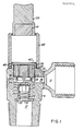
- FIG. 1 there is shown an internal pictorial view of the generally cylindrical housing 9 that is threaded at the lower end for threaded connection directly to the top of a supply cylinder of gas.
- a standard outlet connection 11 is welded 13 to the body 9, for example, by conventional electron-beam welding techniques.
- the body 9 includes an internal, central aperture 15 between inlet channel 17 and outlet channel 19, and includes a surrounding sealing surface or valve seat 21 on the inlet side of the aperture 15.
- Piston element 25 is slidably mounted within inlet channel 17 and carries an elastomeric wafer or seal 23 of suitable material such as a perfluoroelastomer (available as KALREZ from DuPont Co.) for forming a fluid-tight seal with valve seat 21.
- suitable material such as a perfluoroelastomer (available as KALREZ from DuPont Co.) for forming a fluid-tight seal with valve seat 21.
- the piston element 25 includes grooves 27 or flats on its generally cylindrical outer surfaces, for reasons later described, to allow gas under pressure to flow past the piston element 25 and through the aperture 15 (when open) to the outlet channel 19.
- a spring 29 and spring retainer 31 are disposed beneath the piston element 25 to resiliently urge the seal 23 into fluid-tight normally-closed, sealing engagement with the valve seat 21.
- retainer 31 is arranged to pass the fluid under pressure via passage 32, or via a square shape in a cylindrical bore, or the like.
- the pressure-enhanced and spring-enhanced seal 21, 23 is controlled by the central rod 33 which is attached to the piston element 25 and which protrudes through the aperture 15 into the outlet channel 19.
- a slide element 35 containing a magnet 37 encapsulated therein is slidably mounted within the outlet channel to selectively exert control force upon the rod 33 to open the seal formed around aperture 15.
- This element 35 is supported by the spring 29 (via piston 25 and central rod 33), and thus does not affect the normally closed condition of the valve while the actuating button 39 with its encapsulated magnet 41 are in the remotest position, as shown.
- magnets 37 and 41 are repulsion oriented so that the weight of the button 39 and magnet 41 are also supported through such repelling force by the spring 29.
- End plate 40 may be electronbeam welded to the housing 9 at the upper end of the outlet channel 19 to seal the housing against the possibilities of leaks.
- the parts of the present invention may thus be formed of such materials as stainless steel or aluminum or plastic, or the like, to provide welded integrity against leaks without significantly interfering with the controlling magnetic field externally applied by magnet 41.
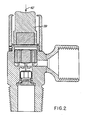
- a cylindrical retainer and guide 43 for button 39 may be attached to the housing by a set screw 45, or other suitable attachment means, to establish the three distinct operating positions of button 39, as illustrated in Figures 1, 2 and 3.
- manual force 42 must be continually applied to button 39 to retain it in the most proximate position, as illustrated, for as long as the valve is to remain open.
- the size, weight, magnetic flux and relative spacing of the magnets 37 and 41, and the spring force exerted by spring 29 may all be selected to establish the above operating mode.
- FIG. 3 the valve embodiment of Figure 1 and 2 is illustrated with the button 39 'latched' in an intermediate position by the intruding upper flange 46 of retainer and guide 43 engaging the shoulder 47 on button 39.
- the combined magnetic repulsion force between magnets 37 and 41, and the weight of element 35 and piston 25, is sufficient to overcome the opposing spring force of spring 29. This retains the valve in open condition with the magnetic force plus weight of element 35 and piston 25 selected to slightly exceed the spring force of spring 29.
- the cross sectional area of these fluid-flow passages is selected to establish an increment of force that is related to the flow rate of fluid (of given density) therethrough.
- a flow rate of fluid through the flats or grooves 27 in excess of a selected value establishes a force that, combined with the spring force of spring 29, lifts the piston 25 and seal 23 into engagement with valve seat 21 against the weight of elements 35 and piston 25 and the repelling force of magnets 37 and 41.
- the valve thus closed by the excess flow of fluid remains closed by the spring-enhanced and pressure-enhanced seal that is formed over aperture 15, until the valve is opened and reset by fully depressing the button 39 to the position and operating mode illustrated and described in connection with Figure 2.
- the illustrated embodiment of the valve of Figures 1, 2 and 3 includes a descending skirt or shield carried by element 35 that includes lateral apertures 52 for passing therethrough the gas that flows through aperture when the valve is fully or partially open.
- the shield 50 is effective to impede the development of additional forces, due to the Bernoulli effect, between element 35 and the surface 54 of housing 9. By the Bernoulli effect, fluid flow at high velocity between two surfaces reduces the pressure, and hence, the relative forces acting on the surfaces.
- the shield 50 with aperture 52 assures that the fluid which flows through open aperture 15 will not reduce the forces acting on element 35 relative to surface 54 of housing 9, and a cause of oscillatory motion of element 35 is thereby eliminated.
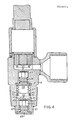
- FIG 4 there is illustrated an embodiment of the present invention that is similar to the embodiment of Figure 1 with the additional features of a pressure regulator included within the body 9, 10. Similar structural elements in figures 1-4 bear the same legend numbers for purposes of clarity, and the additional elements assembled within the inlet channel 17 of housing 9 below the retainer 31 are disposed to operate as a pressure regulator.
- a sealed bellows 55 with flexible side walls 57 is mounted on the under-side of spring retainer 31 to position its end wall 59 at a location that is a function of the differential between the internal and external pressures acting upon the bellows 55.
- the end wall 59 acts upon a central rod 61 which is attached to an auxiliary piston 62 and which protrudes through a second aperture 63 formed within the subhousing 10 that encloses the auxiliary piston 62.
- the auxiliary piston 62 carries an elastomeric seal 65 which is similar to the seal 23 and which forms a fluid-tight seal around aperture 63 that is enhanced by fluid pressure and by spring 67 that is mounted between the auxiliary piston 62 and spring retainer 69 to urge the sealing engagement of seal 65 around aperture 63.
- This fluid-tight seal may be altered and controlled by the position of end plate 59 of bellows 55 acting through rod 61.
- the bellows 55 may be pressurized to a selected gas pressure representative of the value of gas pressure about which pressure regulation is to occur.
- fluid pressure in channel 17 in excess of the bellows pressure causes the end plate 59 to be positioned away from the aperture 63 as the bellows 55 compresses.
- This causes the auxiliary piston 62 with seal 65 to move into sealing engagement with the aperture 63, thereby reducing fluid pressure downstream of the aperture and allowing the bellows 55 to expand.
- fluid pressure in the channel 17 lower than the bellows pressure causes the bellows 55 to expand and position the end plate 59 closer to aperture 63.
- This causes the auxiliary piston 62 with seal 65 to move away from sealing engagement around the aperture 63, thereby allowing fluid flow therethrough and the build up of pressure in inlet 17.
- the fluid pressure downstream of aperture 63 is thus self-regulated about the internal bellows pressure in response to movement of end plate 59 as the bellows 55 expands and compresses in response to fluid pressure in channel 17 acting upon the effective control surface area of the bellows 55.
- the end plate 59 includes a descending skirt or shield 70 with lateral apertures 72 therethrough to reduce the Bernoulli effect of fluid flowing through aperture 63, as previously described in connection with skirt 50, and this reduces possible sources of oscillatory motion of the auxiliary piston 62.
- the apparatus of the present invention is a button-actuated, normally-closed shut-off valve for a gas-supply cylinder that also provides excess-flow cut-off and pressure regulation in a low-profile valve body that obviates the need for sliding or rotating seals.
- the flow control valve of the present invention assures quick, manual shut-off operation simply by unlatching the control button to allow the immediate restoration of pressure-enhanced and spring-enhanced closure against further fluid flow out of the supply cylinder.
Landscapes
- Engineering & Computer Science (AREA)
- General Engineering & Computer Science (AREA)
- Mechanical Engineering (AREA)
- Lift Valve (AREA)
- Magnetically Actuated Valves (AREA)
- Safety Valves (AREA)
- Fluid-Driven Valves (AREA)
Applications Claiming Priority (2)
| Application Number | Priority Date | Filing Date | Title |
|---|---|---|---|
| US83028686A | 1986-02-18 | 1986-02-18 | |
| US830286 | 1986-02-18 |
Publications (2)
| Publication Number | Publication Date |
|---|---|
| EP0233775A2 true EP0233775A2 (fr) | 1987-08-26 |
| EP0233775A3 EP0233775A3 (fr) | 1988-12-14 |
Family
ID=25256675
Family Applications (1)
| Application Number | Title | Priority Date | Filing Date |
|---|---|---|---|
| EP87301340A Withdrawn EP0233775A3 (fr) | 1986-02-18 | 1987-02-17 | Vanne de fermeture et de contrôle pour l'alimentation d'un cylindre |
Country Status (12)
| Country | Link |
|---|---|
| EP (1) | EP0233775A3 (fr) |
| JP (1) | JPS62246663A (fr) |
| KR (1) | KR870008138A (fr) |
| CN (1) | CN87102179A (fr) |
| AU (1) | AU6888587A (fr) |
| BE (1) | BE1000713A4 (fr) |
| DK (1) | DK79787A (fr) |
| FR (1) | FR2600744A1 (fr) |
| GB (1) | GB2186667B (fr) |
| IT (1) | IT1215358B (fr) |
| NO (1) | NO870619L (fr) |
| ZA (1) | ZA871168B (fr) |
Cited By (7)
| Publication number | Priority date | Publication date | Assignee | Title |
|---|---|---|---|---|
| EP0458253A1 (fr) * | 1990-05-22 | 1991-11-27 | VTI Ventil Technik GmbH | Soupape d'arrêt pour un récipient sous pression d'un fluide |
| EP0183205B1 (fr) * | 1984-11-28 | 1991-12-27 | Eidsmore, Paul George | Soupape de réglage du débit |
| EP1382899A1 (fr) * | 2002-07-18 | 2004-01-21 | Soda-Club (CO 2) SA | Une valve pour fermer un réservoir, réservoir et système et procédé de remplissage d'un réservoir |
| EP1328756A4 (fr) * | 2000-04-19 | 2008-09-03 | Advanced Tech Materials | Systeme de stockage et de distribution de gaz comprenant un regulateur place dans un recipient de confinement du fluide et pouvant s'y regler |
| EP1180638A3 (fr) * | 2000-08-18 | 2008-09-03 | Air Products And Chemicals, Inc. | Méthode de distribution de gaz à pression sub-atmosphérique et appareil |
| ITPD20080236A1 (it) * | 2008-07-31 | 2010-02-01 | Cavagna Group S P A Con Socio Unic O | Gruppo valvolare regolatore di pressione per recipienti destinati a contenere fluidi compressi |
| WO2023214965A1 (fr) * | 2022-05-04 | 2023-11-09 | Aerojet Rocketdyne, Inc. | Vanne push-pull |
Families Citing this family (18)
| Publication number | Priority date | Publication date | Assignee | Title |
|---|---|---|---|---|
| US4792113A (en) * | 1982-07-16 | 1988-12-20 | Integrated Flow Systems, Inc. | Fluid flow control valve |
| IT1241869B (it) * | 1990-07-04 | 1994-02-01 | Galli Rosaria & C | Dispositivo di sicurezza antisgancio per rubinetti da bombola di gas liquido provvisti di attacco rapido di utilizzo. |
| IT1288254B1 (it) * | 1996-11-20 | 1998-09-11 | Nova Comet Srl | Unita' di intercettazione con valvola di eccesso di flusso e sistema di svuotamento per bombole di gas |
| US6988556B2 (en) | 2002-02-19 | 2006-01-24 | Halliburton Energy Services, Inc. | Deep set safety valve |
| US8919730B2 (en) | 2006-12-29 | 2014-12-30 | Halliburton Energy Services, Inc. | Magnetically coupled safety valve with satellite inner magnets |
| US8038120B2 (en) | 2006-12-29 | 2011-10-18 | Halliburton Energy Services, Inc. | Magnetically coupled safety valve with satellite outer magnets |
| US7624963B2 (en) * | 2007-02-16 | 2009-12-01 | Fisher Controls International Llc | Valve flow adjustment device |
| KR100784722B1 (ko) * | 2007-03-06 | 2007-12-12 | 주식회사 대우일렉트로닉스 | 스팀청소기의 유량제어장치 |
| US20100162899A1 (en) * | 2008-12-29 | 2010-07-01 | O'brien Stephen J | Portable brewing apparatus |
| CN102062220B (zh) * | 2010-11-05 | 2012-07-25 | 西华大学 | 超高压自动排气、泄压阀 |
| US8573304B2 (en) | 2010-11-22 | 2013-11-05 | Halliburton Energy Services, Inc. | Eccentric safety valve |
| CN102628516B (zh) * | 2012-04-18 | 2013-12-25 | 多立恒(北京)能源技术有限公司 | 直立式液化气钢瓶阀门 |
| MX363439B (es) | 2013-03-15 | 2019-03-22 | Scott Tech Inc | Sistemas para llenar un cilindro de gas. |
| WO2015002063A1 (fr) * | 2013-07-02 | 2015-01-08 | 愛三工業株式会社 | Soupape de régulation du débit et dispositif de traitement de carburant par évaporation doté d'une soupape de régulation du débit |
| CN104500821B (zh) * | 2013-12-18 | 2017-01-18 | 上海艾维科阀门有限公司 | 一种减压阀 |
| CN106704672B (zh) * | 2017-02-06 | 2019-05-07 | 中航空天发动机研究院有限公司 | 一种自激励无功耗脉动气流发生装置 |
| CN112879800B (zh) * | 2021-03-02 | 2021-12-24 | 江苏民诺特种设备有限公司 | 直立式液化气钢瓶用自动充装阀门 |
| CN116464781A (zh) * | 2022-07-22 | 2023-07-21 | 广东万家乐燃气具有限公司 | 一种复位阀芯、连接阀及零冷水循环系统 |
Family Cites Families (5)
| Publication number | Priority date | Publication date | Assignee | Title |
|---|---|---|---|---|
| FR1313173A (fr) * | 1961-11-13 | 1962-12-28 | Robinet détendeur pour gaz liquéfié | |
| FR2067408A5 (fr) * | 1969-11-03 | 1971-08-20 | Air Liquide | |
| US3709255A (en) * | 1971-02-12 | 1973-01-09 | Auto Anti Pollution Devices Of | High pressure valves |
| GB1438957A (en) * | 1972-09-11 | 1976-06-09 | Ti Domestic Appliances Ltd | Fluid flow control valves |
| US4624443A (en) * | 1982-07-16 | 1986-11-25 | Integrated Flow Systems, Inc. | Fluid-flow control valve |
-
1987
- 1987-02-17 EP EP87301340A patent/EP0233775A3/fr not_active Withdrawn
- 1987-02-17 DK DK079787A patent/DK79787A/da not_active Application Discontinuation
- 1987-02-17 AU AU68885/87A patent/AU6888587A/en not_active Abandoned
- 1987-02-17 NO NO870619A patent/NO870619L/no unknown
- 1987-02-17 GB GB8703596A patent/GB2186667B/en not_active Expired - Lifetime
- 1987-02-18 ZA ZA871168A patent/ZA871168B/xx unknown
- 1987-02-18 BE BE8700142A patent/BE1000713A4/fr not_active IP Right Cessation
- 1987-02-18 JP JP62035424A patent/JPS62246663A/ja active Pending
- 1987-02-18 FR FR8702101A patent/FR2600744A1/fr not_active Withdrawn
- 1987-02-18 IT IT8719418A patent/IT1215358B/it active
- 1987-02-18 KR KR870001355A patent/KR870008138A/ko not_active Withdrawn
- 1987-02-18 CN CN87102179A patent/CN87102179A/zh active Pending
Cited By (13)
| Publication number | Priority date | Publication date | Assignee | Title |
|---|---|---|---|---|
| EP0183205B1 (fr) * | 1984-11-28 | 1991-12-27 | Eidsmore, Paul George | Soupape de réglage du débit |
| EP0458253A1 (fr) * | 1990-05-22 | 1991-11-27 | VTI Ventil Technik GmbH | Soupape d'arrêt pour un récipient sous pression d'un fluide |
| EP1328756A4 (fr) * | 2000-04-19 | 2008-09-03 | Advanced Tech Materials | Systeme de stockage et de distribution de gaz comprenant un regulateur place dans un recipient de confinement du fluide et pouvant s'y regler |
| EP1180638A3 (fr) * | 2000-08-18 | 2008-09-03 | Air Products And Chemicals, Inc. | Méthode de distribution de gaz à pression sub-atmosphérique et appareil |
| WO2004010046A1 (fr) * | 2002-07-18 | 2004-01-29 | Soda-Club (Co2) Sa | Valve fermant un recipient, recipient et un systeme et procede pour remplir un recipient |
| US7264024B2 (en) | 2002-07-18 | 2007-09-04 | Soda Club (Co2) Atlantic Gmbh | Valve for closing a container, container and a system and method for filling container |
| EP1382899A1 (fr) * | 2002-07-18 | 2004-01-21 | Soda-Club (CO 2) SA | Une valve pour fermer un réservoir, réservoir et système et procédé de remplissage d'un réservoir |
| EP2273179A3 (fr) * | 2002-07-18 | 2018-02-28 | Soda-Club (CO2) AG | Une valve pour fermer un réservoir, réservoir et système et procédé de remplissage d'un réservoir |
| ITPD20080236A1 (it) * | 2008-07-31 | 2010-02-01 | Cavagna Group S P A Con Socio Unic O | Gruppo valvolare regolatore di pressione per recipienti destinati a contenere fluidi compressi |
| WO2010013135A1 (fr) * | 2008-07-31 | 2010-02-04 | Cavagna Group S.P.A. | Ensemble régulateur de pression pour contenants conçus pour contenir des fluides sous pression |
| US8656945B2 (en) | 2008-07-31 | 2014-02-25 | Cavagna Group S.P.A. | Pressure control valve assembly for containers adapted to contain compressed fluids |
| EP2307788B1 (fr) * | 2008-07-31 | 2018-12-19 | Cavagna Group S.p.A. | Ensemble régulateur de pression pour contenants conçus pour contenir des fluides sous pression |
| WO2023214965A1 (fr) * | 2022-05-04 | 2023-11-09 | Aerojet Rocketdyne, Inc. | Vanne push-pull |
Also Published As
| Publication number | Publication date |
|---|---|
| CN87102179A (zh) | 1987-09-02 |
| NO870619D0 (no) | 1987-02-17 |
| JPS62246663A (ja) | 1987-10-27 |
| DK79787D0 (da) | 1987-02-17 |
| IT1215358B (it) | 1990-02-08 |
| KR870008138A (ko) | 1987-09-24 |
| GB2186667A (en) | 1987-08-19 |
| FR2600744A1 (fr) | 1987-12-31 |
| IT8719418A0 (it) | 1987-02-18 |
| NO870619L (no) | 1987-08-19 |
| GB2186667B (en) | 1990-07-04 |
| EP0233775A3 (fr) | 1988-12-14 |
| DK79787A (da) | 1987-08-19 |
| BE1000713A4 (fr) | 1989-03-21 |
| GB8703596D0 (en) | 1987-03-25 |
| ZA871168B (en) | 1987-08-07 |
| AU6888587A (en) | 1987-08-20 |
Similar Documents
| Publication | Publication Date | Title |
|---|---|---|
| US4793379A (en) | Supply cylinder shut-off and flow control valve | |
| EP0233775A2 (fr) | Vanne de fermeture et de contrôle pour l'alimentation d'un cylindre | |
| US4624443A (en) | Fluid-flow control valve | |
| US4792113A (en) | Fluid flow control valve | |
| US6851658B2 (en) | Control valve trim and bore seal | |
| EP0192625B1 (fr) | Vanne de réglage ayant un diaphragme roulant | |
| EP0434598B1 (fr) | Soupape de réglage à membrane | |
| US6725880B1 (en) | Constant flow control valve | |
| EP0256113A1 (fr) | Dispositif de commande et d'isolation de l'ecoulement d'un fluide. | |
| EP0468621B1 (fr) | Soupape pilote pour soupape de réglage et mode opératoire | |
| US4702277A (en) | Cylinder valve-regulator | |
| US5516079A (en) | Small flow control valve with tight shutoff capability | |
| EP0134866A2 (fr) | Soupape de commande | |
| EP0059599A1 (fr) | Mécanisme de soupape pour application à basse température | |
| IE780576L (en) | Gas lift valve | |
| US5158111A (en) | Pilot valve for pneumatic control systems with improved poppet | |
| US20150192934A1 (en) | Apparatus for controlling pressure and flow of gases, particularly in mining applications | |
| CA1294515C (fr) | Robinet de coupure et de regulation du debit sur cylindre d'alimentation | |
| US4176679A (en) | Check valve | |
| US4982758A (en) | Regulator with fluid supported and operated diaphragm | |
| EP0256114A4 (fr) | Procede de regulation et regulateur de la pression d'un fluide. | |
| JPH05280727A (ja) | 特にガス膨張ステーションにおける安全と自動遮断のための装置 | |
| EP0200543A2 (fr) | Vanne pour la commande d'écoulement de gaz d'une bonbonne cylindrique de gaz à haute pression | |
| US3722534A (en) | Flow control valve system with rapid closing valve | |
| US20030164195A1 (en) | Manually operated tank valve |
Legal Events
| Date | Code | Title | Description |
|---|---|---|---|
| PUAI | Public reference made under article 153(3) epc to a published international application that has entered the european phase |
Free format text: ORIGINAL CODE: 0009012 |
|
| AK | Designated contracting states |
Kind code of ref document: A2 Designated state(s): AT DE LU NL SE |
|
| PUAL | Search report despatched |
Free format text: ORIGINAL CODE: 0009013 |
|
| AK | Designated contracting states |
Kind code of ref document: A3 Designated state(s): AT DE LU NL SE |
|
| 17P | Request for examination filed |
Effective date: 19890609 |
|
| 111L | Licence recorded |
Free format text: 0100 NUPRO COMPANY |
|
| 17Q | First examination report despatched |
Effective date: 19900725 |
|
| STAA | Information on the status of an ep patent application or granted ep patent |
Free format text: STATUS: THE APPLICATION IS DEEMED TO BE WITHDRAWN |
|
| 18D | Application deemed to be withdrawn |
Effective date: 19901106 |