EP0234189A1 - Elektronik-Haushaltsapparat mit elektronischem Programmiergerät mit einer Schnittstelle für die Leistungskomponentensteuerung - Google Patents
Elektronik-Haushaltsapparat mit elektronischem Programmiergerät mit einer Schnittstelle für die Leistungskomponentensteuerung Download PDFInfo
- Publication number
- EP0234189A1 EP0234189A1 EP87100121A EP87100121A EP0234189A1 EP 0234189 A1 EP0234189 A1 EP 0234189A1 EP 87100121 A EP87100121 A EP 87100121A EP 87100121 A EP87100121 A EP 87100121A EP 0234189 A1 EP0234189 A1 EP 0234189A1
- Authority
- EP
- European Patent Office
- Prior art keywords
- circuit breaker
- electric
- household appliance
- program unit
- metallic element
- Prior art date
- Legal status (The legal status is an assumption and is not a legal conclusion. Google has not performed a legal analysis and makes no representation as to the accuracy of the status listed.)
- Granted
Links
- 229910052751 metal Inorganic materials 0.000 claims abstract description 20
- 238000010438 heat treatment Methods 0.000 claims description 3
- 238000010276 construction Methods 0.000 description 3
- 230000004048 modification Effects 0.000 description 3
- 238000012986 modification Methods 0.000 description 3
- 239000011810 insulating material Substances 0.000 description 2
- 238000009877 rendering Methods 0.000 description 2
- 238000005406 washing Methods 0.000 description 2
- 238000010411 cooking Methods 0.000 description 1
- 230000000994 depressogenic effect Effects 0.000 description 1
- 230000005662 electromechanics Effects 0.000 description 1
- 230000010354 integration Effects 0.000 description 1
- 238000010412 laundry washing Methods 0.000 description 1
- 239000007788 liquid Substances 0.000 description 1
- 238000013021 overheating Methods 0.000 description 1
- 230000000717 retained effect Effects 0.000 description 1
Images

Classifications
-
- H—ELECTRICITY
- H05—ELECTRIC TECHNIQUES NOT OTHERWISE PROVIDED FOR
- H05B—ELECTRIC HEATING; ELECTRIC LIGHT SOURCES NOT OTHERWISE PROVIDED FOR; CIRCUIT ARRANGEMENTS FOR ELECTRIC LIGHT SOURCES, IN GENERAL
- H05B1/00—Details of electric heating devices
- H05B1/02—Automatic switching arrangements specially adapted to apparatus ; Control of heating devices
- H05B1/0202—Switches
- H05B1/0213—Switches using bimetallic elements
-
- G—PHYSICS
- G05—CONTROLLING; REGULATING
- G05D—SYSTEMS FOR CONTROLLING OR REGULATING NON-ELECTRIC VARIABLES
- G05D23/00—Control of temperature
- G05D23/19—Control of temperature characterised by the use of electric means
- G05D23/1917—Control of temperature characterised by the use of electric means using digital means
-
- G—PHYSICS
- G05—CONTROLLING; REGULATING
- G05D—SYSTEMS FOR CONTROLLING OR REGULATING NON-ELECTRIC VARIABLES
- G05D23/00—Control of temperature
- G05D23/19—Control of temperature characterised by the use of electric means
- G05D23/20—Control of temperature characterised by the use of electric means with sensing elements having variation of electric or magnetic properties with change of temperature
- G05D23/24—Control of temperature characterised by the use of electric means with sensing elements having variation of electric or magnetic properties with change of temperature the sensing element having a resistance varying with temperature, e.g. a thermistor
-
- H—ELECTRICITY
- H01—ELECTRIC ELEMENTS
- H01H—ELECTRIC SWITCHES; RELAYS; SELECTORS; EMERGENCY PROTECTIVE DEVICES
- H01H37/00—Thermally-actuated switches
- H01H37/002—Thermally-actuated switches combined with protective means
-
- H—ELECTRICITY
- H01—ELECTRIC ELEMENTS
- H01H—ELECTRIC SWITCHES; RELAYS; SELECTORS; EMERGENCY PROTECTIVE DEVICES
- H01H61/00—Electrothermal relays
- H01H61/02—Electrothermal relays wherein the thermally-sensitive member is heated indirectly, e.g. resistively, inductively
Definitions
- the present invention relates to an electric household appliance such as a dishwasher, a laundry washing machine, a cooking oven or the like of the type having an electronic program unit for controlling the operation of the electric appliance.
- such electronic program units usually comprise a microprocessor operating at low current value and thus requiring suitable interface devices enabling it to control high-power electrical compnents of the appliance such as an electric resistance heater.
- interface devices include controlled power curcuit breakers such as TRIAC or SCR, although these components are undesirably expensive and only relatively reliable. It is therefore sometimes preferred to employ electromechanic relays under the control of low-power TRIAC or SCR components, which are much more reliable in operation, but also this solution appears unsatisfactory due to the complicated construction resulting therefrom, to the increased space requirements, and to the possibility of sticking of the electric contacts of the relay.
- an electric household appliance having an electronic program unit for controlling at least one electric high-power component through an interface device comprising at least one controlled low-power circuit breaker controlled by an output of the program unit, at least one electric circuit breaker connected in the energizing circuit of the respective high-power component and at least one thermistor in heat-exchange relationship to at least one bi-metallic element cooperating with said electric circuit breaker for switching it between a first and a second operative position.
- An electric household appliance of this type is characterized according to the invention in that said thermistor is arranged in series with said controlled circuit breaker and said high-power component is arranged in series with said electric circuit breaker, both series arrangements being connected across the terminals of said energizing circuit.
- the interface device is of a particularly simple construction and is preferably integrated in other devices, for instance, safety devices, provided in the electric household appliance according to the invention.
- the electric household appliance comprises an electronic program unit generally indicated at 24 and operable to control the operation of the various low-power and high-power electric components of the appliance.
- fig. 1 depicts only one of the high-power components of the appliance, in this case an electric resistance heater 5 of a washing machine.
- Heater 5 is secured to a wall 6 of the washing tub of the machine and adapted to be connected to the terminals 7,8 of an electric power supply through a main power switch 9 and an electric circuit breaker 10 connected in series therewith comprising a fixed contact 11 and a normally closed movable contact 12.
- circuit breaker 10 As also shown in fig. 2, movable contact 12 of circuit breaker 10 is connected to one terminal of a thermistor 13, preferably of the positive temperature coefficient type (PCT), the other terminal of which is connected to terminal 7 through a controlled low-power circuit breaker 14.
- Circuit breaker 14 may for instance be a TRIAC of the type TLC 381 S adapted to a maximum current value of about 1 A.
- the control electrode of circuit breaker 14 is connected to a control output terminal 15 or program unit 24 for the supply of low-current control signals.
- Thermistor 13 and TRIAC 145 are thus connected in series between terminals 7 and 8 in parallel to the series-connencted resistance heater 5 and circuit breaker 10, and through main power switch 9.
- Thermistor 13 is mounted in heat-transmitting contact with a bi-metallic element 16 mechanically coupled to movable contact 12 of circuit breaker 10 through an actuating plunger 17 of an insulating material.
- bi-metallic element 16 is adapted to be deformed on attaining a predetermined temperature so as to switch circuit breaker 10 from its normally closed state to its open state.
- circuit breaker 10 preferably forms part of another per se known component already provided in the electric household appliance.
- circuit breaker 10 may be part of a thermostatic overheat protection device comprising a further bi-metallic element 18 mounted in heat-transmitting contact with tub wall 6 in proximity to resistance heater 5.
- bi-metallic element 18 is mechanically coupled to movable contact 12 of circuit breaker 10 by means of an actuating plunger 19 of an insulating material extending substantially parallel to plunger 17.
- Bi-metallic element 18 is likewise adapted to be deformed as the predetermined safety temperature is attained for switching curcuit breaker 10 from its nomally closed state to the open state.
- a control input terminal 20 of electronic program unit 24 is connected in a per se known manner to a sensor 21 adapted to detect the internal temperature of tub 6.
- Operation of the appliance is started by closing main power switch 9 for energizing resistance heater 5.
- program unit 24 produces a signal at output terminal 15 for rendering TRIAC 14 conductive, whereby thermistor 13, which is originally cold and has therefore a low resistance value, is rapidly heated by the current flowing therethrough, and transmits the thus generated heat to bi-metallic element 16.
- element 16 being deformed in a short time of about 3 seconds, so as to open circuit breaker 10 by means of plunger 17.
- the electric power supply to heater 5, thermistor 13 and TRIAC 14 is interrupted after a negligibly short period of time during which heater 5 had been energized, while the resistance of thermistor 13 rises with its temperature, until it acts as an open switch.
- resistance heater 5 is in the state of being energized for heating the liquid contained in tub 6 after bi-metallic element 16 and thermistor 13 have cooled down.
- the cooling-down of the these two elements 13 and 16, and the resultant re-deformation of bi-metallic element 16 requires a relatively long time in the order of several tens of seconds, whereby the operation of the appliance is not, however, unduly influenced.
- program unit 24 When program unit 24 by the action of sensor 21 determines that the predetermined internal temperature of tub 6 has been attained, it generates in a per se known manner a control signal at output terminal 15 for rendering TRIAC 14 conductive. As described above, the resultant rapid heating of thermistor 13 and thus bi-metallic element 16 causes circuit breaker 10 to be opened for de-energizing resistance heater 5.
- bi-metallic element 18 which is suitably calibrated to be deformed at a higher temperature than bimetallic element 16, is deformed so as to open circuit breaker 10 by the action of plunger 19 for de-energizing heater 5.
- the electric household appliance under consideration may, of course, be of any type other than the one described, and may undergo various modifications within the scope of the invention.
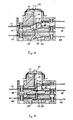
- the electronic program unit 24 may thus be designed to generate the control signal at its output terminal 15 at any other time, and the interface device may be designed in the manner shown in figs 3 and 4, wherein identical components are designated by the same reference numerals as above.
- contact 11 of electric circuit breaker 10 is resiliently deformed to the open state as shown in fig. 3, but is normally retained in the closed state of circuit breaker 10 by the action of actuating plunger 19 (fig. 4).
- Plunger 19 cooperates with a per se known safety button 22 itself biased by a resilient element 23 towards a projecting position (fig. 3).
- safety button 22 is adapted to cooperate with a loading door of the electric appliance. In particular, when the door is closed, safety button 22 is depressed as shown in fig. 4, while with the door open, resilient member 23 maintains safety button 22 in its projecting position shown in fig. 3.
- circuit breaker 10 is opened not only when thermistor 13 and bi-metallic element 16 (acting on contact 12) are heated, but also when the door of the electric appliance is opened. That is because, in this case, contact 11 is permitted to assume the resiliently deformed configuration shown in fig. 3 for opening the circuit breaker even when thermistor 13 and bi-metallic element 16 are below the predetermined operating temperature.
- the main components of the interface device can also be fully integrated in an electric appliance having additional electric circuit breakers similar to the one indicated at 10.
- a suitable support structure may thus carry an additional circuit breaker 25 having contacts 26 and 28 and mounted parallel to circuit breaker 10 thereabove or below.
- a further insulating actuating plunger 27 is freely slidable in a guide bore 29 for transmitting the movements of bi-metallic element 16 to normally closed contact 28 via actuating plunger 17 and movable contact 12.
- Circuit breaker 25 thus operates simultaneously with circuit breaker 10 and my suitably be employed for controlling the energization of another high-power component of the electric appliance or for interrupting the connection to the other terminal of electric resistance heater 5.
Landscapes
- Physics & Mathematics (AREA)
- General Physics & Mathematics (AREA)
- Engineering & Computer Science (AREA)
- Automation & Control Theory (AREA)
- Thermally Actuated Switches (AREA)
- Control Of Resistance Heating (AREA)
- Cookers (AREA)
- Keying Circuit Devices (AREA)
- Electric Stoves And Ranges (AREA)
- Surgical Instruments (AREA)
- Warehouses Or Storage Devices (AREA)
- Stored Programmes (AREA)
- Control By Computers (AREA)
Priority Applications (1)
| Application Number | Priority Date | Filing Date | Title |
|---|---|---|---|
| AT87100121T ATE51969T1 (de) | 1986-01-13 | 1987-01-07 | Elektronik-haushaltsapparat mit elektronischem programmiergeraet mit einer schnittstelle fuer die leistungskomponentensteuerung. |
Applications Claiming Priority (2)
| Application Number | Priority Date | Filing Date | Title |
|---|---|---|---|
| IT4570186 | 1986-01-13 | ||
| IT45701/86A IT1191524B (it) | 1986-01-13 | 1986-01-13 | Elettrodomestico a programmatore elettronico con interfaccia per il comando di organi di potenza |
Publications (2)
| Publication Number | Publication Date |
|---|---|
| EP0234189A1 true EP0234189A1 (de) | 1987-09-02 |
| EP0234189B1 EP0234189B1 (de) | 1990-04-11 |
Family
ID=11257332
Family Applications (1)
| Application Number | Title | Priority Date | Filing Date |
|---|---|---|---|
| EP87100121A Expired - Lifetime EP0234189B1 (de) | 1986-01-13 | 1987-01-07 | Elektronik-Haushaltsapparat mit elektronischem Programmiergerät mit einer Schnittstelle für die Leistungskomponentensteuerung |
Country Status (5)
| Country | Link |
|---|---|
| EP (1) | EP0234189B1 (de) |
| AT (1) | ATE51969T1 (de) |
| DE (1) | DE3762293D1 (de) |
| ES (1) | ES2014256B3 (de) |
| IT (1) | IT1191524B (de) |
Cited By (3)
| Publication number | Priority date | Publication date | Assignee | Title |
|---|---|---|---|---|
| WO2000031480A1 (en) * | 1998-11-24 | 2000-06-02 | Miller Europe S.P.A. | Device for controlling the service loads of an electric household appliance, in particular a refrigerator |
| EP1041594A3 (de) * | 1999-03-31 | 2001-12-05 | Sanyo Electric Co., Ltd. | Thermostat und Batteriesatz mit dem Thermostat versehen |
| CN111128600A (zh) * | 2020-01-17 | 2020-05-08 | 杭州科美特传感器有限公司 | 一种断路机构、温度保护断路器以及电加热电器 |
Citations (5)
| Publication number | Priority date | Publication date | Assignee | Title |
|---|---|---|---|---|
| US2897321A (en) * | 1958-04-30 | 1959-07-28 | Fred D Patti | Control unit for electric heating appliances |
| FR1387402A (fr) * | 1963-10-02 | 1965-01-29 | Robertshaw Controls Co | Montages de commande de température |
| FR1561786A (de) * | 1967-05-05 | 1969-03-28 | Siemens Elektrogeraete Gmbh | Perfectionnements aux appareils de chaufage électriques |
| US3931560A (en) * | 1972-01-10 | 1976-01-06 | Robertshaw Controls Company | Motor control system and electrical switch constructions therefor or the like |
| EP0052871A2 (de) * | 1980-11-20 | 1982-06-02 | Kabushiki Kaisha Toshiba | Programmierbarer elektronischer Kochapparat |
-
1986
- 1986-01-13 IT IT45701/86A patent/IT1191524B/it active
-
1987
- 1987-01-07 EP EP87100121A patent/EP0234189B1/de not_active Expired - Lifetime
- 1987-01-07 DE DE8787100121T patent/DE3762293D1/de not_active Expired - Fee Related
- 1987-01-07 ES ES87100121T patent/ES2014256B3/es not_active Expired - Lifetime
- 1987-01-07 AT AT87100121T patent/ATE51969T1/de not_active IP Right Cessation
Patent Citations (5)
| Publication number | Priority date | Publication date | Assignee | Title |
|---|---|---|---|---|
| US2897321A (en) * | 1958-04-30 | 1959-07-28 | Fred D Patti | Control unit for electric heating appliances |
| FR1387402A (fr) * | 1963-10-02 | 1965-01-29 | Robertshaw Controls Co | Montages de commande de température |
| FR1561786A (de) * | 1967-05-05 | 1969-03-28 | Siemens Elektrogeraete Gmbh | Perfectionnements aux appareils de chaufage électriques |
| US3931560A (en) * | 1972-01-10 | 1976-01-06 | Robertshaw Controls Company | Motor control system and electrical switch constructions therefor or the like |
| EP0052871A2 (de) * | 1980-11-20 | 1982-06-02 | Kabushiki Kaisha Toshiba | Programmierbarer elektronischer Kochapparat |
Cited By (5)
| Publication number | Priority date | Publication date | Assignee | Title |
|---|---|---|---|---|
| WO2000031480A1 (en) * | 1998-11-24 | 2000-06-02 | Miller Europe S.P.A. | Device for controlling the service loads of an electric household appliance, in particular a refrigerator |
| US6660976B1 (en) | 1998-11-24 | 2003-12-09 | Itw Industrial Components S.R.L. | Device for controlling the service loads of an electric household appliance, in particular a refrigerator |
| US6894253B2 (en) | 1998-11-24 | 2005-05-17 | Itw Industrial Components S.R.L. | Device for controlling the service loads of an electric household appliance, in particular a refrigerator |
| EP1041594A3 (de) * | 1999-03-31 | 2001-12-05 | Sanyo Electric Co., Ltd. | Thermostat und Batteriesatz mit dem Thermostat versehen |
| CN111128600A (zh) * | 2020-01-17 | 2020-05-08 | 杭州科美特传感器有限公司 | 一种断路机构、温度保护断路器以及电加热电器 |
Also Published As
| Publication number | Publication date |
|---|---|
| ES2014256B3 (es) | 1990-07-01 |
| IT8645701A0 (it) | 1986-01-13 |
| IT1191524B (it) | 1988-03-23 |
| ATE51969T1 (de) | 1990-04-15 |
| EP0234189B1 (de) | 1990-04-11 |
| DE3762293D1 (de) | 1990-05-17 |
Similar Documents
| Publication | Publication Date | Title |
|---|---|---|
| US4788415A (en) | Dual bimetal power control switching arrangement for electronically controlled appliances | |
| US3364338A (en) | Oven temperature control | |
| US4528558A (en) | Door-open alarm device for a refrigerating appliance | |
| US4803342A (en) | Flat-iron safety device utilizing a dual internal timing circuit | |
| US2427945A (en) | Electric hot plate with vesseltemperature control | |
| US6080967A (en) | Combined user actuation and thermostat switch assembly | |
| US4394646A (en) | Temperature indicator for a glass ceramic cooking surface | |
| CA1202089A (en) | Heating chamber damper mechanism | |
| US2422526A (en) | Heating system | |
| US2526566A (en) | Automatic temperature control electric circuit | |
| US3435189A (en) | Thermostatic control system for water heater tanks or the like | |
| EP0234189B1 (de) | Elektronik-Haushaltsapparat mit elektronischem Programmiergerät mit einer Schnittstelle für die Leistungskomponentensteuerung | |
| US4383156A (en) | Control circuit for controlling a magnetron of a microwave oven | |
| US3412236A (en) | Oven control system and method for operating the same or the like | |
| US1697040A (en) | Electrically-controlled apparatus | |
| JP3247325B2 (ja) | サーマルリレー及びこれを用いた制御回路 | |
| US3093722A (en) | Domestic heating appliance | |
| US3246119A (en) | Water heater and control therefor | |
| US3656182A (en) | Hydraulic thermostat with double throw switch mechanism | |
| GB2350734A (en) | Method of controlling a heating element of an electric device for heating a liquid | |
| US1928907A (en) | Heater control | |
| US3064102A (en) | Thermoresponsive switch means | |
| US11570853B2 (en) | Method for actuating a heating device of a hob, and hob | |
| WO1993016569A1 (en) | Immersion heaters | |
| US3036189A (en) | Electric cooking range |
Legal Events
| Date | Code | Title | Description |
|---|---|---|---|
| PUAI | Public reference made under article 153(3) epc to a published international application that has entered the european phase |
Free format text: ORIGINAL CODE: 0009012 |
|
| AK | Designated contracting states |
Kind code of ref document: A1 Designated state(s): AT BE CH DE ES FR GB IT LI LU NL SE |
|
| RAP1 | Party data changed (applicant data changed or rights of an application transferred) |
Owner name: INDUSTRIE ZANUSSI S.P.A. |
|
| 17P | Request for examination filed |
Effective date: 19880210 |
|
| 17Q | First examination report despatched |
Effective date: 19890601 |
|
| ITF | It: translation for a ep patent filed | ||
| GRAA | (expected) grant |
Free format text: ORIGINAL CODE: 0009210 |
|
| RAP1 | Party data changed (applicant data changed or rights of an application transferred) |
Owner name: INDUSTRIE ZANUSSI S.P.A. |
|
| AK | Designated contracting states |
Kind code of ref document: B1 Designated state(s): AT BE CH DE ES FR GB IT LI LU NL SE |
|
| REF | Corresponds to: |
Ref document number: 51969 Country of ref document: AT Date of ref document: 19900415 Kind code of ref document: T |
|
| ET | Fr: translation filed | ||
| REF | Corresponds to: |
Ref document number: 3762293 Country of ref document: DE Date of ref document: 19900517 |
|
| PLBE | No opposition filed within time limit |
Free format text: ORIGINAL CODE: 0009261 |
|
| STAA | Information on the status of an ep patent application or granted ep patent |
Free format text: STATUS: NO OPPOSITION FILED WITHIN TIME LIMIT |
|
| 26N | No opposition filed | ||
| PGFP | Annual fee paid to national office [announced via postgrant information from national office to epo] |
Ref country code: AT Payment date: 19931213 Year of fee payment: 8 |
|
| PGFP | Annual fee paid to national office [announced via postgrant information from national office to epo] |
Ref country code: LU Payment date: 19931216 Year of fee payment: 8 |
|
| PGFP | Annual fee paid to national office [announced via postgrant information from national office to epo] |
Ref country code: CH Payment date: 19931217 Year of fee payment: 8 |
|
| PGFP | Annual fee paid to national office [announced via postgrant information from national office to epo] |
Ref country code: BE Payment date: 19931227 Year of fee payment: 8 |
|
| EPTA | Lu: last paid annual fee | ||
| PGFP | Annual fee paid to national office [announced via postgrant information from national office to epo] |
Ref country code: SE Payment date: 19941219 Year of fee payment: 9 |
|
| PG25 | Lapsed in a contracting state [announced via postgrant information from national office to epo] |
Ref country code: LU Free format text: LAPSE BECAUSE OF NON-PAYMENT OF DUE FEES Effective date: 19950107 Ref country code: AT Effective date: 19950107 |
|
| PGFP | Annual fee paid to national office [announced via postgrant information from national office to epo] |
Ref country code: ES Payment date: 19950116 Year of fee payment: 9 |
|
| EAL | Se: european patent in force in sweden |
Ref document number: 87100121.0 |
|
| PG25 | Lapsed in a contracting state [announced via postgrant information from national office to epo] |
Ref country code: LI Effective date: 19950131 Ref country code: CH Effective date: 19950131 Ref country code: BE Effective date: 19950131 |
|
| PGFP | Annual fee paid to national office [announced via postgrant information from national office to epo] |
Ref country code: NL Payment date: 19950131 Year of fee payment: 9 |
|
| BERE | Be: lapsed |
Owner name: INDUSTRIE ZANUSSI S.P.A. Effective date: 19950131 |
|
| REG | Reference to a national code |
Ref country code: CH Ref legal event code: PL |
|
| PG25 | Lapsed in a contracting state [announced via postgrant information from national office to epo] |
Ref country code: SE Effective date: 19960108 Ref country code: ES Free format text: LAPSE BECAUSE OF NON-PAYMENT OF DUE FEES Effective date: 19960108 |
|
| PG25 | Lapsed in a contracting state [announced via postgrant information from national office to epo] |
Ref country code: NL Effective date: 19960801 |
|
| NLV4 | Nl: lapsed or anulled due to non-payment of the annual fee |
Effective date: 19960801 |
|
| EUG | Se: european patent has lapsed |
Ref document number: 87100121.0 |
|
| REG | Reference to a national code |
Ref country code: ES Ref legal event code: FD2A Effective date: 19990201 |
|
| REG | Reference to a national code |
Ref country code: GB Ref legal event code: IF02 |
|
| PGFP | Annual fee paid to national office [announced via postgrant information from national office to epo] |
Ref country code: FR Payment date: 20021209 Year of fee payment: 17 |
|
| PGFP | Annual fee paid to national office [announced via postgrant information from national office to epo] |
Ref country code: GB Payment date: 20021212 Year of fee payment: 17 |
|
| PGFP | Annual fee paid to national office [announced via postgrant information from national office to epo] |
Ref country code: DE Payment date: 20021213 Year of fee payment: 17 |
|
| PG25 | Lapsed in a contracting state [announced via postgrant information from national office to epo] |
Ref country code: GB Free format text: LAPSE BECAUSE OF NON-PAYMENT OF DUE FEES Effective date: 20040107 |
|
| PG25 | Lapsed in a contracting state [announced via postgrant information from national office to epo] |
Ref country code: DE Free format text: LAPSE BECAUSE OF NON-PAYMENT OF DUE FEES Effective date: 20040803 |
|
| GBPC | Gb: european patent ceased through non-payment of renewal fee |
Effective date: 20040107 |
|
| PG25 | Lapsed in a contracting state [announced via postgrant information from national office to epo] |
Ref country code: FR Free format text: LAPSE BECAUSE OF NON-PAYMENT OF DUE FEES Effective date: 20040930 |
|
| REG | Reference to a national code |
Ref country code: FR Ref legal event code: ST |
|
| PG25 | Lapsed in a contracting state [announced via postgrant information from national office to epo] |
Ref country code: IT Free format text: LAPSE BECAUSE OF NON-PAYMENT OF DUE FEES Effective date: 20050107 |