EP0234653B1 - Fördervorrichtung - Google Patents
Fördervorrichtung Download PDFInfo
- Publication number
- EP0234653B1 EP0234653B1 EP87200254A EP87200254A EP0234653B1 EP 0234653 B1 EP0234653 B1 EP 0234653B1 EP 87200254 A EP87200254 A EP 87200254A EP 87200254 A EP87200254 A EP 87200254A EP 0234653 B1 EP0234653 B1 EP 0234653B1
- Authority
- EP
- European Patent Office
- Prior art keywords
- trolley
- load
- belt
- trajectory
- cable
- Prior art date
- Legal status (The legal status is an assumption and is not a legal conclusion. Google has not performed a legal analysis and makes no representation as to the accuracy of the status listed.)
- Expired
Links
- 238000009434 installation Methods 0.000 title claims description 19
- 238000006073 displacement reaction Methods 0.000 claims description 4
- 230000000063 preceeding effect Effects 0.000 claims 1
- 239000000725 suspension Substances 0.000 claims 1
- 238000010276 construction Methods 0.000 description 6
- 230000002349 favourable effect Effects 0.000 description 3
- 241000282472 Canis lupus familiaris Species 0.000 description 2
- 230000005484 gravity Effects 0.000 description 2
- 239000000969 carrier Substances 0.000 description 1
- 238000000151 deposition Methods 0.000 description 1
- 230000000284 resting effect Effects 0.000 description 1
- 238000005096 rolling process Methods 0.000 description 1
Images


Classifications
-
- B—PERFORMING OPERATIONS; TRANSPORTING
- B65—CONVEYING; PACKING; STORING; HANDLING THIN OR FILAMENTARY MATERIAL
- B65G—TRANSPORT OR STORAGE DEVICES, e.g. CONVEYORS FOR LOADING OR TIPPING, SHOP CONVEYOR SYSTEMS OR PNEUMATIC TUBE CONVEYORS
- B65G47/00—Article or material-handling devices associated with conveyors; Methods employing such devices
- B65G47/74—Feeding, transfer, or discharging devices of particular kinds or types
- B65G47/94—Devices for flexing or tilting travelling structures; Throw-off carriages
- B65G47/96—Devices for tilting links or platform
- B65G47/962—Devices for tilting links or platform tilting about an axis substantially parallel to the conveying direction
- B65G47/965—Devices for tilting links or platform tilting about an axis substantially parallel to the conveying direction tilting about a sided-axis, i.e. the axis is not located near the center-line of the load-carrier
-
- B—PERFORMING OPERATIONS; TRANSPORTING
- B65—CONVEYING; PACKING; STORING; HANDLING THIN OR FILAMENTARY MATERIAL
- B65G—TRANSPORT OR STORAGE DEVICES, e.g. CONVEYORS FOR LOADING OR TIPPING, SHOP CONVEYOR SYSTEMS OR PNEUMATIC TUBE CONVEYORS
- B65G17/00—Conveyors having an endless traction element, e.g. a chain, transmitting movement to a continuous or substantially-continuous load-carrying surface or to a series of individual load-carriers; Endless-chain conveyors in which the chains form the load-carrying surface
- B65G17/30—Details; Auxiliary devices
- B65G17/32—Individual load-carriers
- B65G17/34—Individual load-carriers having flat surfaces, e.g. platforms, grids, forks
- B65G17/345—Individual load-carriers having flat surfaces, e.g. platforms, grids, forks the surfaces being equipped with a conveyor
-
- B—PERFORMING OPERATIONS; TRANSPORTING
- B65—CONVEYING; PACKING; STORING; HANDLING THIN OR FILAMENTARY MATERIAL
- B65G—TRANSPORT OR STORAGE DEVICES, e.g. CONVEYORS FOR LOADING OR TIPPING, SHOP CONVEYOR SYSTEMS OR PNEUMATIC TUBE CONVEYORS
- B65G2201/00—Indexing codes relating to handling devices, e.g. conveyors, characterised by the type of product or load being conveyed or handled
- B65G2201/02—Articles
-
- B—PERFORMING OPERATIONS; TRANSPORTING
- B65—CONVEYING; PACKING; STORING; HANDLING THIN OR FILAMENTARY MATERIAL
- B65G—TRANSPORT OR STORAGE DEVICES, e.g. CONVEYORS FOR LOADING OR TIPPING, SHOP CONVEYOR SYSTEMS OR PNEUMATIC TUBE CONVEYORS
- B65G2207/00—Indexing codes relating to constructional details, configuration and additional features of a handling device, e.g. Conveyors
- B65G2207/18—Crossing conveyors
Definitions
- the invention concerns a conveyor installation comprising a guiding member or beam forming a closed trajectory, at least one trolley travelling along said guiding member and fitted with a load carrier for a load to be delivered into one of a series of delivery stations situated along said trajectory, the load carrier comprising driven means to throw off the load at a pre-determined delivery station, said driven throw-off means being formed by at least one continuous belt passing around some pulleys, the belt being subjected to a sideways displacement perpendicular to the direction of travel along the trajectory by means of power released after the lifting of a catch.
- Such an installation is known from FR-A'2 475 015, and is used for sorting objects which are thrown off the load carrier into the correct delivery station along the trajectory of the conveyor. Provision is made, mostly controlled by a computer for selective throwing off so that the object concerned (the load) arrive at the correct station. The energy required for this throwing off movement is derived from the driving means of the trolleys limiting the speed of operation.
- the invention intends to provide an installation with an independent energy source to throw off the load into an delivery station without using a special motor for this purpose.
- the object is achieved according to the invention in that at least a part of the trolley is movably mounted with respect to its remaining part so as to be displaceable in relation to the load carrier and in that in a zone of the trajectory preceding the delivery stations, a track surface is provided, having a sloping portion, a wheel or roller connected to said movable part of the trolley engaging said surface, such that each trolley will accumulate an amount of energy whilst traversing said zone of the trajectory preceding the delivery stations which energy is locked by the re-engagement of the catch.
- the driven throw-off means is actuated at the chosen moment by the release of energy previously accumulated during a vertical displacement of a trolley part.
- the throwing off is obtained by drive means independent from the driving means of the trolleys.
- the drive means can consist of, for example, a spring which is previously tensioned using the forwards movement of the trolley.
- the driven throw-off means are being formed by at least one continuous belt which passes around pulleys, the belt moving around the pulleys in a direction perpendicular to the direction of travel along the trajectory, as also known per se from FR-A--2 475 015
- the proposed installation is distinct in that the movable part of each trolley is suspended from the remaining part of the trolley and carries the driven throw-off means of the load carrier, such that after the lifting of the catch said load carrier can fall freely, whereby the power needed to drive at least one of the pulleys is furnished by the downward movement of said suspended trolley part relative to the forward travelling trolley part.
- the movable trolley part also carries the load, sufficient power is generated to throw off this load sideways at an appreciable speed. In a further portion of the trajectory this trolley part can be moved back upwards and the catch reset ready for receiving a new load and depositing this at the correct spot.
- a simple contructional solution for converting the downward movement of the movable trolley part into sideways movement of the belt is preferably obtained according to the invention by mounting at least one of the pulleys on a rotatable axle upon which a cable is wound, the free end of which is attached to the forward travelling trolley part in such a way that during the downward movement of the movable trolley part the cable wound around the axle unwinds turning the pulley concerned and thus driving the belt so as to throw off the load sideways.
- the vertically movable trolley part is suspended by means of two quadrangular fink- ages each consisting by two pivots upon the forward travelling trolley part and by two pivots upon the movable trolley part, said pivots being connected pairwise by a long and mainly horizontally extending arm and by a short inclined arm respectively, said quadrangular linkages composed by these arms lying on either side of the movable trolley part.
- the stiffness can be markedly increased in a very simple manner by combining the short arms of both quandrangular linkages into a plate which has a common hinge axis for the pivots concerned on two of its sides.
- the increased stiffness is particularly noticeable in the direction parallel to the travel of the trolley along the trajectory.
- the invention proposes in a preferred embodiment to make the length and width of the belt the same as the dimensions of the load carrier and to connect the ends of several narrow belts to each end of the load belt in order to tension it and to cooperate with the driven pulleys.
- the belt can be designed entirely for its function of receiving and throwing off the load, whilst the necessary sideways driving force for throwing off the load is created by the cooperation of the narrow belts and the pulleys.
- FIG. 1 shows a construction of a conveyor-sorter installation consisting of a number of load carriers 1 for a load to be delivered.
- Each load carrier 1 is supported in a frame or trolley 2 (see Fig. 2) which travels along a trajectory formed by a fixed guiding member or profile beam 3. This trajectory is shown here as elongate and has two turning points 4.
- the trolleys 2 are coupled together by an endless beltorchain 5 mostly driven (not shown) at one of the turning points 4.
- the described installation is conventional up to this point.
- the load carrier 1 is formed by a belt 7 round some pulleys 6.
- the pulleys 6 are rotatable as will be described later, so that the belt 7 can be moved in a direction perpendicular to that of the trajectory (the profile beam 3). Seeing that the load to be transported and sorted is on this belt 7 the load can thus be thrown off sideways.
- the power required for driving the belt 7 is obtained by splitting the frame or trolley 2 into a forward-travelling part 8 and a vertically-displaceable part 9.
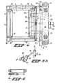
- Part 8 is made up from a plate 10 which is fitted on the top side with a bearing and guiding construction 12-15, to cooperate with the profile beam 3 and which Will be described later, whilst two support rollers 11 contacting the inner side of the profile beam 3 are mounted on the under side.
- the bearing and guiding construction just mentioned consists of an elongated block 12 (see Fig. 5 also) with on either side of the middle two rotatable swing pieces 13 are mounted.
- Two rotatable guide rollers 14 are mounted in each swing piece 13. These guide rollers are in contact with the outside of the profile beam 3.
- Block 12 is fitted furtherwith two rollers 15 which rest on the top side of the profile beam 3 and bear the whole weight of the trolley 2. That dscribes the forward travelling frame part 8.
- the vertically-displaceable part 9 consists of two side plates 16 (see Fig. 4 also) which are connected to each other by some strips 17. These elements 16 and 17 form in the main the vertically displaceable part 9 that is hung on two quadrangular linkages.
- For these two pivots 18 and 19 are mounted on both side plates 16 whilst two times two pivots 20 and 21 are mounted on plate 10 of the forward-travelling trolley part 8.
- Pivots 18 and 20 are jointed in pairs by a longer, almost horizontal arm 22.
- Pivots 19 and 21 are joined to each other by a plate 23 which has a common axis for both pivots 19 on the one side and on the other a common axis for both pivots 21.
- the load carrier 1 formed by the belt 7 that is mounted over some pulleys 6 is situated above the side plates 16.
- the two pulleys 6 shown on the right of Fig. 3 are fixed on an axle 24 which is provided with means to drive the pulleys.
- These means consist of a first cable 25 which is wound round axle 24 and connected with its free end to the forward-travelling trolley part 8.
- a second cable 27 is alos wound around axle 24 of the driving pulleys but in the opposite sense to cable 25.
- the free end 28 of this second cable 27 is also connected to the forward-travelling trolley part 8 via a spring member 29.
- the vertically displacement trolley part 9 is fitted with a projecting pin 30 (see Fig. 2 and 4) which together with a locking catch 31 can hold this part in its highest position.
- the catch 31 is mounted on the end of an axle 32 which is borne in block 12.
- the other end of axle 32 is fitted to a lever arm 33 connected to a roller 34.
- Each trolley 2 is fitted with a similar mechanism 31-34 so that a controlled free fall movement of the displaceable trolley part 9 relative to the forward-travelling trolley part 8 is made possible.
- a number of delivery stations 35 for example designed as a roller course, in which the throw off loads must land are placed on the outside of the trajectory along which the trolleys 2 travel.
- a tiltable cam 36 is mounted upon the fixed profile beam 3. This cam is normally lying horizontally as shown dotted in Fig. 5A, so that no contact is made with the roller 34.
- an electromagnet not shown
- the cam 36 can be moved to the sloping position shown. The necessary signal for this is given by the computer system used or in some other way.
- the first arriving trolley 2 that passes the sloping cam 36 receives an impulse because roller 34 comes in contact with cam 36.
- axle 32 with the catch 31 is turned so that pin 30 is freed and the trolley part 9 can move downwards under the force of gravity.
- Lever arm 33 can only be turned through a limited angle because of the restriction 37, whilst a spring 38 exerts pressure on arm 33 for two purposes.
- axle 32 with catch 31 are forced back into the position shown in Fig. 5b, whilst the cam 36 is also forced back from the sloping to the horizontal position.
- the displaceable trolley part 9 moves downwards and is guided here by arms 22 and plate 23 of the rectangular linkages.
- the downwards movement of part 9 is limited by the presence of a rail 39 extending parallel to the profile beam 3 at a suitable distance beyond this beam.
- Part 9 is fitted with a wheel 40 underneath which ends up resting on rail 39.
- the rail 39 is raised 39' so that any parts 9 which have fallen down are moved upwards again and pin 30 can be held by catch 31.
- the free fall movement of part 9 is such that near the top of the falling movement pin 30 moves in the vertical plane through catch 31. In this way it is guaranteed that catch 31 will relock pin 30 during travelling along the highest part 39' of rail 39.
- the load carrier tilts slightly, which is favourable for throwing off the load quickly. This tilt is caused by using the long and short arms 22 and 23.
- each trolley 2 is transported by the endless chain 5 by means of a pivotal dog 42, linked to block 12, see Fig. 5A.
- a projecting pick-up rib 43 fitted onto belt 7.
- this conveyor installation makes it possible to throw off any load present on the load carrier 1 in a direction perpendicular to the trajectory followed by the trolleys.
- a belt 7 moving over some pulleys 6 with a mechanism to drive at least one of the pulleys using the energy accumulated whilst a previous portion of the trajectory is traversed (the raised part 39').
- Fig. 6 shows a very schematically drawn variation in which use is made of a spring 44 which is tensioned during the passing of the raised portion 39'. In that case the frame part 9 moves upwards at the same time as the spring is brought under tension. With the help of catch 31 or an equivalent mechanism the taut spring can be fixed and released again at the correct moment to start the movement of the belt 7 in order to throw off the load sideways.
Landscapes
- Engineering & Computer Science (AREA)
- Mechanical Engineering (AREA)
- Discharge Of Articles From Conveyors (AREA)
- Intermediate Stations On Conveyors (AREA)
- Structure Of Belt Conveyors (AREA)
Claims (7)
Applications Claiming Priority (2)
| Application Number | Priority Date | Filing Date | Title |
|---|---|---|---|
| NL8600433 | 1986-02-20 | ||
| NL8600433A NL8600433A (nl) | 1986-02-20 | 1986-02-20 | Transportinrichting. |
Publications (2)
| Publication Number | Publication Date |
|---|---|
| EP0234653A1 EP0234653A1 (de) | 1987-09-02 |
| EP0234653B1 true EP0234653B1 (de) | 1990-12-19 |
Family
ID=19847605
Family Applications (1)
| Application Number | Title | Priority Date | Filing Date |
|---|---|---|---|
| EP87200254A Expired EP0234653B1 (de) | 1986-02-20 | 1987-02-17 | Fördervorrichtung |
Country Status (6)
| Country | Link |
|---|---|
| US (1) | US4763771A (de) |
| EP (1) | EP0234653B1 (de) |
| JP (1) | JPH07106771B2 (de) |
| CA (1) | CA1270787A (de) |
| DE (1) | DE3766713D1 (de) |
| NL (1) | NL8600433A (de) |
Families Citing this family (28)
| Publication number | Priority date | Publication date | Assignee | Title |
|---|---|---|---|---|
| JPH0676136B2 (ja) * | 1988-03-24 | 1994-09-28 | オークラ輸送機株式会会社 | 搬送装置 |
| IT1217694B (it) * | 1988-05-23 | 1990-03-30 | Francesco Canziani | Metodo per il controllo dell'esatto posizionamento degli oggetti da smistare in un impianto di smistamento automatico |
| US4938335A (en) * | 1988-05-23 | 1990-07-03 | Francesco Canziani | Method and devices for controlling the unloading of the items in an automatic sorting plant |
| NL9100108A (nl) * | 1991-01-23 | 1992-08-17 | Promech Sorting Syst | Transport- en verdeelinstallatie. |
| DE4236507C1 (de) * | 1992-10-29 | 1993-12-02 | Licentia Gmbh | Umladebrücke |
| IT1263946B (it) * | 1993-02-19 | 1996-09-05 | Smistatrice con piani di trasporto inclinati, con dispositivi per l'attuazione dello scarico azionati dai piani stessi | |
| EP0700844B2 (de) * | 1994-09-06 | 2005-08-10 | Siemens AG | Sortiersystem mit Querband |
| NL1000315C2 (nl) * | 1995-05-08 | 1996-11-11 | Promech Sorting Syst | Inrichting voor het sorteren van goederen. |
| IT237284Y1 (it) * | 1995-11-16 | 2000-09-05 | Cml Handling Technology S P A | Carrello per impianti di smisatmento,con piano di trasportoposizionabile su piu' livelli |
| US5901830A (en) * | 1997-01-22 | 1999-05-11 | Electrocom Automation, L.P. | Bi-directional belt sorter |
| DE19801706A1 (de) * | 1998-01-17 | 1999-07-22 | Axmann Foerdertechnik | Vorrichtung zum Sortieren von Stückgütern |
| US6202824B1 (en) * | 1999-06-15 | 2001-03-20 | International Business Machines Corporation | Vehicle for facilitating assembly verification test |
| US6371032B1 (en) * | 1999-09-01 | 2002-04-16 | Siemens Electrocom, L.P. | Trolley with passive discharge mechanism |
| US6390275B1 (en) * | 1999-12-21 | 2002-05-21 | United Parcel Service Of America, Inc. | High speed parcel sorter |
| US6732849B2 (en) * | 2001-10-11 | 2004-05-11 | Daifuku Co., Ltd. | Sorting system |
| AU2003284237A1 (en) * | 2002-10-16 | 2004-05-04 | Transport Systems, Inc. | Monorail sortation system |
| US8776694B2 (en) | 2002-10-16 | 2014-07-15 | Cross Belt Ip, Llc | Monorail sortation system |
| US9102336B2 (en) | 2002-10-16 | 2015-08-11 | Cross Belt Ip, L.L.C. | Portable bin for sortation system |
| US6669001B1 (en) | 2002-11-12 | 2003-12-30 | Mathews Conveyor, Inc. | Linear belt sorter and methods of using linear belt sorter |
| US7080725B2 (en) * | 2002-12-03 | 2006-07-25 | Sanki Engineering Co., Ltd. | Sorting conveyor provided with cross sorter |
| US7684034B2 (en) * | 2007-05-24 | 2010-03-23 | Applied Vision Company, Llc | Apparatus and methods for container inspection |
| JP6007375B2 (ja) * | 2012-02-15 | 2016-10-12 | 株式会社錦河 | 物品仕分方法と物品仕分装置 |
| JP2016044056A (ja) * | 2014-08-25 | 2016-04-04 | 株式会社東芝 | 物品仕分装置 |
| CN105774207B (zh) * | 2014-12-26 | 2018-12-21 | 深圳富泰宏精密工业有限公司 | 定位装置 |
| CN111729852B (zh) * | 2020-04-23 | 2022-07-05 | 北京京东乾石科技有限公司 | 分拣车、货物分拣系统及货物分拣方法 |
| CN112918533A (zh) * | 2021-01-25 | 2021-06-08 | 银龙 | 一种建筑工地用短钢筋运送装置 |
| CN113697420A (zh) * | 2021-08-02 | 2021-11-26 | 杭州肖育科技有限公司 | 一种磁性材料加工用原料输送设备 |
| CN117284759B (zh) * | 2023-10-30 | 2025-09-23 | 中冶华天工程技术有限公司 | 一种取钢装置以及取钢接钢系统 |
Family Cites Families (9)
| Publication number | Priority date | Publication date | Assignee | Title |
|---|---|---|---|---|
| US3463298A (en) * | 1967-05-16 | 1969-08-26 | Spra Con Co The | Tray constructions for conveyors |
| US3550748A (en) * | 1968-07-23 | 1970-12-29 | Itt | Conveyor arrangement |
| US3616895A (en) * | 1970-03-23 | 1971-11-02 | United Parcel Service General | Conveyor belt indexing mechanism |
| CA989884A (en) * | 1972-04-10 | 1976-05-25 | Richard L. Speaker | Conveying apparatus including tilting support structures |
| JPS537650B2 (de) * | 1972-05-19 | 1978-03-20 | ||
| US4004681A (en) * | 1976-04-05 | 1977-01-25 | American Chain & Cable Company, Inc. | Tilting tray sorting system |
| US4378062A (en) * | 1978-10-30 | 1983-03-29 | Acco Industries Inc. | Tilting carrier system |
| NL185259C (nl) * | 1979-07-13 | 1990-03-01 | Benier Bv | Deegbak voor een rijskast. |
| IT1131422B (it) * | 1980-03-14 | 1986-06-25 | Studsvik Energiteknik Ab | Guarnizione antifiamma |
-
1986
- 1986-02-20 NL NL8600433A patent/NL8600433A/nl not_active Application Discontinuation
-
1987
- 1987-02-17 DE DE8787200254T patent/DE3766713D1/de not_active Expired - Fee Related
- 1987-02-17 EP EP87200254A patent/EP0234653B1/de not_active Expired
- 1987-02-18 JP JP62036843A patent/JPH07106771B2/ja not_active Expired - Lifetime
- 1987-02-18 US US07/016,096 patent/US4763771A/en not_active Expired - Fee Related
- 1987-02-20 CA CA000530241A patent/CA1270787A/en not_active Expired
Also Published As
| Publication number | Publication date |
|---|---|
| JPH07106771B2 (ja) | 1995-11-15 |
| NL8600433A (nl) | 1987-09-16 |
| CA1270787A (en) | 1990-06-26 |
| EP0234653A1 (de) | 1987-09-02 |
| JPS62196220A (ja) | 1987-08-29 |
| US4763771A (en) | 1988-08-16 |
| DE3766713D1 (de) | 1991-01-31 |
Similar Documents
| Publication | Publication Date | Title |
|---|---|---|
| EP0234653B1 (de) | Fördervorrichtung | |
| US4846335A (en) | Sorter tilt mechanism | |
| US5590995A (en) | Conveying rail system for a trolly | |
| US5664660A (en) | Sorter conveyor | |
| US3650216A (en) | Railway car speed control transportation system | |
| US4759439A (en) | Drive mechanism | |
| US4542698A (en) | Power-and-free trolley conveyor of floor type | |
| US5277124A (en) | Direction control assembly for a material handling car having pivoted divert aims engaging tracks for guidance in switch area | |
| EP0354461B1 (de) | Transportvorrichtung | |
| US3730330A (en) | Sensor locking accumulator | |
| US5819906A (en) | Suspension conveyor installation | |
| EP0762985A1 (de) | Vorrichtung zum Transport von Gegenständen | |
| CA1069847A (en) | Cart conveyor system | |
| US4138008A (en) | Heavy duty conveyor | |
| JP2000296769A (ja) | ケーブル上を行き来する少なくとも1つの搬送体もしくは類似する乗り物を備えた搬送装置 | |
| US3420188A (en) | Dog positioning mechanism for conveyor carriers | |
| US3945485A (en) | Tray conveying apparatus | |
| US4361225A (en) | Actuator belt accumulator | |
| US5960938A (en) | Conveyor for cantilevered loads | |
| US4287829A (en) | Carrier stopping device for power-and-free conveyor | |
| US3511359A (en) | Article transporting system | |
| US4699266A (en) | Transporting apparatus for conveying carriers | |
| US3565012A (en) | Conveyor carrier control system | |
| US3793965A (en) | Accumulating load trolley and conveyor system | |
| US4612861A (en) | Driverless tugger vehicle |
Legal Events
| Date | Code | Title | Description |
|---|---|---|---|
| PUAI | Public reference made under article 153(3) epc to a published international application that has entered the european phase |
Free format text: ORIGINAL CODE: 0009012 |
|
| AK | Designated contracting states |
Kind code of ref document: A1 Designated state(s): BE CH DE ES FR GB IT LI NL |
|
| 17P | Request for examination filed |
Effective date: 19870923 |
|
| 17Q | First examination report despatched |
Effective date: 19880929 |
|
| RAP3 | Party data changed (applicant data changed or rights of an application transferred) |
Owner name: GEERTS, JOHANNES GERHARDUS CHRISTIANUS |
|
| DIN1 | Information on inventor provided before grant (deleted) | ||
| RIN1 | Information on inventor provided before grant (corrected) |
Inventor name: GEERTS, JOHANNES GERHARDUS CHRISTIANUS |
|
| RAP1 | Party data changed (applicant data changed or rights of an application transferred) |
Owner name: GEERTS-VEEN, CATHARINA AFIEN Owner name: GEERTS, JAN CHARLES Owner name: GEERTS, STEFAN |
|
| GRAA | (expected) grant |
Free format text: ORIGINAL CODE: 0009210 |
|
| AK | Designated contracting states |
Kind code of ref document: B1 Designated state(s): BE CH DE ES FR GB IT LI NL |
|
| PG25 | Lapsed in a contracting state [announced via postgrant information from national office to epo] |
Ref country code: IT Free format text: LAPSE BECAUSE OF FAILURE TO SUBMIT A TRANSLATION OF THE DESCRIPTION OR TO PAY THE FEE WITHIN THE PRE;WARNING: LAPSES OF ITALIAN PATENTS WITH EFFECTIVE DATE BEFORE 2007 MAY HAVE OCCURRED AT ANY TIME BEFORE 2007. THE CORRECT EFFECTIVE DATE MAY BE DIFFERENT FROM THE ONE RECORDED.SCRIBED TIME-LIMIT Effective date: 19901219 Ref country code: LI Effective date: 19901219 Ref country code: FR Effective date: 19901219 Ref country code: CH Effective date: 19901219 Ref country code: BE Effective date: 19901219 |
|
| REF | Corresponds to: |
Ref document number: 3766713 Country of ref document: DE Date of ref document: 19910131 |
|
| PG25 | Lapsed in a contracting state [announced via postgrant information from national office to epo] |
Ref country code: GB Effective date: 19910219 |
|
| REG | Reference to a national code |
Ref country code: CH Ref legal event code: PL |
|
| PG25 | Lapsed in a contracting state [announced via postgrant information from national office to epo] |
Ref country code: ES Free format text: LAPSE BECAUSE OF FAILURE TO SUBMIT A TRANSLATION OF THE DESCRIPTION OR TO PAY THE FEE WITHIN THE PRESCRIBED TIME-LIMIT Effective date: 19910330 |
|
| EN | Fr: translation not filed | ||
| GBPC | Gb: european patent ceased through non-payment of renewal fee | ||
| PLBE | No opposition filed within time limit |
Free format text: ORIGINAL CODE: 0009261 |
|
| STAA | Information on the status of an ep patent application or granted ep patent |
Free format text: STATUS: NO OPPOSITION FILED WITHIN TIME LIMIT |
|
| 26N | No opposition filed | ||
| NLS | Nl: assignments of ep-patents |
Owner name: PROMECH SORTING SYSTEMS B.V. TE HAARLEM. |
|
| PGFP | Annual fee paid to national office [announced via postgrant information from national office to epo] |
Ref country code: NL Payment date: 19930228 Year of fee payment: 7 |
|
| PGFP | Annual fee paid to national office [announced via postgrant information from national office to epo] |
Ref country code: DE Payment date: 19930429 Year of fee payment: 7 |
|
| PG25 | Lapsed in a contracting state [announced via postgrant information from national office to epo] |
Ref country code: NL Effective date: 19940901 |
|
| NLV4 | Nl: lapsed or anulled due to non-payment of the annual fee | ||
| PG25 | Lapsed in a contracting state [announced via postgrant information from national office to epo] |
Ref country code: DE Effective date: 19941101 |