EP0234697A2 - Schneider - Google Patents
Schneider Download PDFInfo
- Publication number
- EP0234697A2 EP0234697A2 EP87300311A EP87300311A EP0234697A2 EP 0234697 A2 EP0234697 A2 EP 0234697A2 EP 87300311 A EP87300311 A EP 87300311A EP 87300311 A EP87300311 A EP 87300311A EP 0234697 A2 EP0234697 A2 EP 0234697A2
- Authority
- EP
- European Patent Office
- Prior art keywords
- blades
- cutter
- body member
- cutting
- cutting blades
- Prior art date
- Legal status (The legal status is an assumption and is not a legal conclusion. Google has not performed a legal analysis and makes no representation as to the accuracy of the status listed.)
- Withdrawn
Links
Images
Classifications
-
- E—FIXED CONSTRUCTIONS
- E21—EARTH OR ROCK DRILLING; MINING
- E21B—EARTH OR ROCK DRILLING; OBTAINING OIL, GAS, WATER, SOLUBLE OR MELTABLE MATERIALS OR A SLURRY OF MINERALS FROM WELLS
- E21B29/00—Cutting or destroying pipes, packers, plugs or wire lines, located in boreholes or wells, e.g. cutting of damaged pipes, of windows; Deforming of pipes in boreholes or wells; Reconditioning of well casings while in the ground
- E21B29/002—Cutting, e.g. milling, a pipe with a cutter rotating along the circumference of the pipe
Definitions
- This invention relates to a cutter for use in oil well bores.
- One application of the cutter of the invention is in the removal of packers from oil well bores.
- Oil well bores are provided with packers which fit within the well bore and may, for example, be provided with a valve or some other assembly.
- the packers commonly comprise a metal cylindrical body which is secured in the well bore by means of upward and downward facing barbs which prevent, respectively, upwards and downwards movement of the packer within the well bore.
- Such packers may become damaged and have to be removed from the well bore. This is achieved by lowering a milling cutter into the well bore on the end of a drill string and rotating the milling cutter to remove the upward facing barbs from the packer. A retrieving tool is then used to remove the remaining parts of the packer from the well bore.
- a cutter comprising an elongate body member, one end portion of the body member being provided with drill string connecting means, the opposite end portion of the body member being provided with a first set of cutting blades, wherein a second set of cutting blades, of greater radial extension than said first set of cutting blades, is provided intermediate said end portions of the body member.
- the first set of blades are helically mounted on the body member.
- Four blades may be provided and the blades may be dressed with tube borium or a material having similar properties.
- the second set of blades are helically mounted on the body member. Twelve blades may be provided and may have carbide cutting bits.
- the carbide may be provided in the form of inserts retained in brass.
- the body member is provided with a central through bore to allow the passage of drilling mud through the cutter.
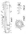
- a cutter for use in the removal of packers from oil well bores comprises an elongate body member l, one end portion of the body member l being provided with drill string connecting means 2, the opposite end portion of the body member being provided with a first set of cutting blades 3, a second set of cutting blades 4 being located intermediate said end portions of the body member l.
- the body member l is in the form of an elongate cylinder and is provided with a central through bore 5 to permit the passage of drilling mud through the cutter.
- the drill string connecting means 2 is in the form of a standard cone type screw thread 6 to enable the cutter to be fixed to the end of a drill string (not shown).
- a drive bushing 7 is located on the body member l adjacent the screw thread 6.
- the first set of cutting blades 3 is located adjacent the rounded free end of the body member l.
- Four blades 8 are provided and are mounted on the body member l in a left hand helix.
- the blades 8 are of steel and are dressed with tube borium 9 to provide a hard cutting surface.
- each blade 8 is eight inches long, one and a quarter inches wide and three-quarters of an inch thick and has 45° inward sloping ends l0.
- the blades 8 are fixed to the body member l and are turned until they define a radius of eight and three-eighths of an inch.
- the layer of tube borium 9 is then applied and ground until the outer face of the blades 8 define a diameter of eight and a half inches.
- the second set of blades 4 extends along the surface of the body member l from the drive bushing 7. Twelve blades ll are provided and are welded to the body member l at a 3° left hand helix. Each blade ll comprises a steel mounting portion l2 and a cutting portion l3 which is formed from a plurality of carbide inserts l4 set in brass l5.
- each steel mounting portion l2 is fourteen and a quarter inches long, two and a half inches wide and three-eights of an inch thick below the cutting portion l3 and has a thicker end portion l6 adjacent the drive bushing 7.
- the thicker end portions l6 are turned until the outer edges define a diameter of eleven and one-eight inch and the leading edges l7 of the blades ll are diametered and machined so that the leading edge l7 are in line.
- carbide inserts l4 and brass l5 are laid on each mounting portion l2.
- the carbide inserts l4 are three-eights of an inch diameter SANDVIK RCMX l0 0300 Grade S6 (uncoated) and are arranged in alternate radial layers of three and four along the mounting portion l2.
- the layers of inserts l4 are arranged such that adjacent blades ll alternate between having a three insert layer l8 leading edge and a four insert layer l9 leading edge.
- a further layer of one-eighth of an inch thick brass 20 is applied to the leading edges l7 before the blades ll are ground to a diameter of eleven inches.
Landscapes
- Life Sciences & Earth Sciences (AREA)
- Engineering & Computer Science (AREA)
- Geology (AREA)
- Mining & Mineral Resources (AREA)
- Physics & Mathematics (AREA)
- Environmental & Geological Engineering (AREA)
- Fluid Mechanics (AREA)
- General Life Sciences & Earth Sciences (AREA)
- Geochemistry & Mineralogy (AREA)
- Earth Drilling (AREA)
- Processing Of Stones Or Stones Resemblance Materials (AREA)
Applications Claiming Priority (2)
| Application Number | Priority Date | Filing Date | Title |
|---|---|---|---|
| GB868601110A GB8601110D0 (en) | 1986-01-17 | 1986-01-17 | Cutter |
| GB8601110 | 1986-01-17 |
Publications (2)
| Publication Number | Publication Date |
|---|---|
| EP0234697A2 true EP0234697A2 (de) | 1987-09-02 |
| EP0234697A3 EP0234697A3 (de) | 1988-11-30 |
Family
ID=10591532
Family Applications (1)
| Application Number | Title | Priority Date | Filing Date |
|---|---|---|---|
| EP87300311A Withdrawn EP0234697A3 (de) | 1986-01-17 | 1987-01-15 | Schneider |
Country Status (3)
| Country | Link |
|---|---|
| EP (1) | EP0234697A3 (de) |
| GB (1) | GB8601110D0 (de) |
| NO (1) | NO870198L (de) |
Cited By (7)
| Publication number | Priority date | Publication date | Assignee | Title |
|---|---|---|---|---|
| EP0341073A1 (de) * | 1988-05-06 | 1989-11-08 | Smith International, Inc. | Blatt für ein Rohrschneidwerkzeug und Verfahren zu dessen Herrichtung |
| EP0339776A3 (de) * | 1988-04-15 | 1990-03-28 | Tri-State Oil Tool Industries Inc. | Schneidwerkzeug und Methode zur Entfernung von Material aus dem Bohrloch |
| EP0397417A1 (de) * | 1989-05-09 | 1990-11-14 | Smith International, Inc. | Fräsgerät mit auswechselbaren Schneiden |
| US8327957B2 (en) | 2010-06-24 | 2012-12-11 | Baker Hughes Incorporated | Downhole cutting tool having center beveled mill blade |
| US8434572B2 (en) | 2010-06-24 | 2013-05-07 | Baker Hughes Incorporated | Cutting elements for downhole cutting tools |
| US8936109B2 (en) | 2010-06-24 | 2015-01-20 | Baker Hughes Incorporated | Cutting elements for cutting tools |
| US9151120B2 (en) | 2012-06-04 | 2015-10-06 | Baker Hughes Incorporated | Face stabilized downhole cutting tool |
Family Cites Families (10)
| Publication number | Priority date | Publication date | Assignee | Title |
|---|---|---|---|---|
| US2034074A (en) * | 1934-10-06 | 1936-03-17 | Jesse C Wright | Well drill |
| US2855994A (en) * | 1956-07-23 | 1958-10-14 | Jr Archer W Kammerer | Milling apparatus |
| US2846193A (en) * | 1957-01-07 | 1958-08-05 | Chadderdon Jack | Milling cutter for use in oil wells |
| US2833520A (en) * | 1957-01-07 | 1958-05-06 | Robert G Owen | Annular mill for use in oil wells |
| US2904313A (en) * | 1957-03-12 | 1959-09-15 | Lorenzer D V Wisenbaker | Key-seat reamer |
| US3110084A (en) * | 1958-08-15 | 1963-11-12 | Robert B Kinzbach | Piloted milling tool |
| FR1249499A (fr) * | 1959-11-19 | 1960-12-30 | Europ De Turboforage Soc | équipement pour le forage du sol |
| US3114416A (en) * | 1961-11-13 | 1963-12-17 | Archer W Kammerer | Liner hanger and liner milling tool |
| US3429387A (en) * | 1967-03-06 | 1969-02-25 | Cicero C Brown | Pump out drill bit |
| WO1983002641A1 (en) * | 1982-01-27 | 1983-08-04 | Steinkamp, Manfred | Oil well packer retriever |
-
1986
- 1986-01-17 GB GB868601110A patent/GB8601110D0/en active Pending
-
1987
- 1987-01-15 EP EP87300311A patent/EP0234697A3/de not_active Withdrawn
- 1987-01-16 NO NO870198A patent/NO870198L/no unknown
Cited By (7)
| Publication number | Priority date | Publication date | Assignee | Title |
|---|---|---|---|---|
| EP0339776A3 (de) * | 1988-04-15 | 1990-03-28 | Tri-State Oil Tool Industries Inc. | Schneidwerkzeug und Methode zur Entfernung von Material aus dem Bohrloch |
| EP0341073A1 (de) * | 1988-05-06 | 1989-11-08 | Smith International, Inc. | Blatt für ein Rohrschneidwerkzeug und Verfahren zu dessen Herrichtung |
| EP0397417A1 (de) * | 1989-05-09 | 1990-11-14 | Smith International, Inc. | Fräsgerät mit auswechselbaren Schneiden |
| US8327957B2 (en) | 2010-06-24 | 2012-12-11 | Baker Hughes Incorporated | Downhole cutting tool having center beveled mill blade |
| US8434572B2 (en) | 2010-06-24 | 2013-05-07 | Baker Hughes Incorporated | Cutting elements for downhole cutting tools |
| US8936109B2 (en) | 2010-06-24 | 2015-01-20 | Baker Hughes Incorporated | Cutting elements for cutting tools |
| US9151120B2 (en) | 2012-06-04 | 2015-10-06 | Baker Hughes Incorporated | Face stabilized downhole cutting tool |
Also Published As
| Publication number | Publication date |
|---|---|
| EP0234697A3 (de) | 1988-11-30 |
| NO870198D0 (no) | 1987-01-16 |
| NO870198L (no) | 1987-07-20 |
| GB8601110D0 (en) | 1986-02-19 |
Similar Documents
| Publication | Publication Date | Title |
|---|---|---|
| US4323130A (en) | Drill bit | |
| USRE32036E (en) | Drill bit | |
| US4724913A (en) | Drill bit and improved cutting element | |
| US5443565A (en) | Drill bit with forward sweep cutting elements | |
| US4478297A (en) | Drill bit having cutting elements with heat removal cores | |
| EP2097613B1 (de) | Verbessertes bohrlochschab- und/oder bürstenwerkzeug sowie zugehörige verfahren | |
| US4381825A (en) | Drill bit nozzle | |
| US4494618A (en) | Drill bit with self cleaning nozzle | |
| EP1096103B1 (de) | Bi-zentrales Bohrzeug zum Bohren durch Verrohrungsschuh | |
| CA1325802C (en) | Cutting tool for removing man-made members from well bore | |
| US7025156B1 (en) | Rotary drill bit for casting milling and formation drilling | |
| US8061456B2 (en) | Chamfered edge gage cutters and drill bits so equipped | |
| US7117960B2 (en) | Bits for use in drilling with casting and method of making the same | |
| JPS63156606A (ja) | ミ−リング工具 | |
| US4442909A (en) | Drill bit | |
| US4512425A (en) | Up-drill sub for use in rotary drilling | |
| US3110084A (en) | Piloted milling tool | |
| US3052310A (en) | Combined reamer and drill string stabilizer | |
| GB2313863A (en) | A steel body PDC bit | |
| GB2101703A (en) | Scraping tool | |
| EP0234697A2 (de) | Schneider | |
| EP0058061A2 (de) | Erdbohrwerkzeug | |
| CA2207809C (en) | Cutting bed impeller | |
| US4632196A (en) | Drill bit with shrouded cutter | |
| US5099935A (en) | Reinforced rotary drill bit |
Legal Events
| Date | Code | Title | Description |
|---|---|---|---|
| PUAI | Public reference made under article 153(3) epc to a published international application that has entered the european phase |
Free format text: ORIGINAL CODE: 0009012 |
|
| AK | Designated contracting states |
Kind code of ref document: A2 Designated state(s): DE GB NL |
|
| PUAL | Search report despatched |
Free format text: ORIGINAL CODE: 0009013 |
|
| AK | Designated contracting states |
Kind code of ref document: A3 Designated state(s): DE GB NL |
|
| 17P | Request for examination filed |
Effective date: 19890117 |
|
| 17Q | First examination report despatched |
Effective date: 19891030 |
|
| STAA | Information on the status of an ep patent application or granted ep patent |
Free format text: STATUS: THE APPLICATION IS DEEMED TO BE WITHDRAWN |
|
| 18D | Application deemed to be withdrawn |
Effective date: 19900510 |
|
| RIN1 | Information on inventor provided before grant (corrected) |
Inventor name: WINTERROWD, KENNETH WALTER Inventor name: HARVEY, HAROLD HARRY, JR. Inventor name: LYNDE, GERALD DAVID |