EP0235100A2 - Vorrichtung zum periodischen Betätigen eines oder mehrerer Stempel in einer Presse - Google Patents
Vorrichtung zum periodischen Betätigen eines oder mehrerer Stempel in einer Presse Download PDFInfo
- Publication number
- EP0235100A2 EP0235100A2 EP87830070A EP87830070A EP0235100A2 EP 0235100 A2 EP0235100 A2 EP 0235100A2 EP 87830070 A EP87830070 A EP 87830070A EP 87830070 A EP87830070 A EP 87830070A EP 0235100 A2 EP0235100 A2 EP 0235100A2
- Authority
- EP
- European Patent Office
- Prior art keywords
- disk
- teeth
- punches
- ram
- guide plate
- Prior art date
- Legal status (The legal status is an assumption and is not a legal conclusion. Google has not performed a legal analysis and makes no representation as to the accuracy of the status listed.)
- Withdrawn
Links
Images


Classifications
-
- H—ELECTRICITY
- H02—GENERATION; CONVERSION OR DISTRIBUTION OF ELECTRIC POWER
- H02K—DYNAMO-ELECTRIC MACHINES
- H02K15/00—Processes or apparatus specially adapted for manufacturing, assembling, maintaining or repairing of dynamo-electric machines
- H02K15/02—Processes or apparatus specially adapted for manufacturing, assembling, maintaining or repairing of dynamo-electric machines of stator or rotor bodies
-
- B—PERFORMING OPERATIONS; TRANSPORTING
- B21—MECHANICAL METAL-WORKING WITHOUT ESSENTIALLY REMOVING MATERIAL; PUNCHING METAL
- B21D—WORKING OR PROCESSING OF SHEET METAL OR METAL TUBES, RODS OR PROFILES WITHOUT ESSENTIALLY REMOVING MATERIAL; PUNCHING METAL
- B21D28/00—Shaping by press-cutting; Perforating
- B21D28/02—Punching blanks or articles with or without obtaining scrap; Notching
- B21D28/22—Notching the peripheries of circular blanks, e.g. laminations for dynamo-electric machines
-
- B—PERFORMING OPERATIONS; TRANSPORTING
- B21—MECHANICAL METAL-WORKING WITHOUT ESSENTIALLY REMOVING MATERIAL; PUNCHING METAL
- B21D—WORKING OR PROCESSING OF SHEET METAL OR METAL TUBES, RODS OR PROFILES WITHOUT ESSENTIALLY REMOVING MATERIAL; PUNCHING METAL
- B21D28/00—Shaping by press-cutting; Perforating
- B21D28/24—Perforating, i.e. punching holes
- B21D28/246—Selection of punches
-
- B—PERFORMING OPERATIONS; TRANSPORTING
- B30—PRESSES
- B30B—PRESSES IN GENERAL
- B30B15/00—Details of, or accessories for, presses; Auxiliary measures in connection with pressing
- B30B15/0029—Details of, or accessories for, presses; Auxiliary measures in connection with pressing means for adjusting the space between the press slide and the press table, i.e. the shut height
- B30B15/0035—Details of, or accessories for, presses; Auxiliary measures in connection with pressing means for adjusting the space between the press slide and the press table, i.e. the shut height using an adjustable connection between the press drive means and the press slide
Definitions
- the present invention relates to a device to periodically actuate one or more punches in a press. More particularly the device in question is adapted to be used in presses designed to make laminations for electrical equipments such as motors, alternators, transformers and the like.
- laminations are individually submitted to simultaneous blanking and drawing operations which give rise to one or more cut and projecting portions on the surface thereof.
- Laminations thus worked are then disposed upon each other in a predetermined amount depending upon the heigth of the pack it is wished to obtain and then joined to each other by forcibly engaging the projecting portions of each lamination into the spaces existing on the adjoining lamination.
- said laminations are provided with through holes adapted to be engaged by the projections of the adjacent laminations. The ends of said projections will substantially be flush with the outer surface of the pack itself.
- the packing method briefly described above uses presses equipped with several operating stations, through which a plate strip is caused to advance stepwise in synchronism with the press movements, from which plate strip the individual laminations and afterwards the packs are obtained. More particularly provision is made for one or more operating stations where holes and shapings are machined on the plate strip depending upon the surface appearance to be exhibited by the finished lamination, an operating station where surface projections are carried out and an operating station where the separation of the individual laminations from the plate strip and the simultaneous packwise arrangement of the same take place. A further station is also provided which operates periodically and is designed to create through holes instead of projections on those laminations that are destined to form the pack ends.
- punches are provided to be slidably engaged with a guide plate carried by the press ram. When at rest, punches have their respective penetration points hidden inside the guide plate, and are kept in this position by return springs acting between the support plate and the punches themselves.
- An actuating device essentially consisting of a cam-shaped element operated by a double effect air cylinder acts on the punch ends opposite those provided with said penetration points.
- the air cylinder upon impulsion of a control unit associated with the press and suitably programmed, acts in such a way that it causes the cam-shaped element to move sideways each time after a predetermined number of strokes of the ram. As a result of said displacement, punches reach their operating position, that is the penetration points come out of the guide plate.
- a further drawback of the known art is due to the fact that presently used.control units cause punches to be actuated on the basis of the numeral counting of blows carried out by the press ram. Therefore the formation of packs is obtained by using a predetermined number of laminations for each pack depending upon the nominal thickness of the plate strip and the heigth of the packs it is wished to obtain.
- the object of the present invention is to eliminate the above drawbacks and particularly to provide a device designed to periodically actuate the punches which is capable of running at the same speed as the maximum operating speed of the press with which it is associated or even at a higher speed.
- a device to periodically actuate one or more punches in a press in which the workpiece is interposed between a die supported by a fixed bed and a guide plate connected by the interposition of spring means to a ram provided with reciprocating motion in the direction of said die, said punches slidably crossing the guide plate and being movable from an operating position in which they protrude from the guide plate in the direction of said die, each in the region of a penetration point thereof, to a rest position in which said penetration point is hidden inside said guide plate, characterized in that it comprises a support plate secured underneath the ram and elastically supporting said guide plate, at least two posts fastened to said bed with which the guide plate and support plate slidably engage, a crosspiece rigidly supported by said posts and slidably engaging within a recess provided in said support plate on the same side as the ram, a disk oscillatably engaged between said support plate and said guide plate and supporting said punche
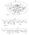
- a device to periodically actuate one or more punches in a press has been globally identified by reference numeral 1.
- the device 1 is associated with a press adapted to produce and pack laminations used in electronical equipments.
- device 1 is provided to be mounted in an operating station in which the piercing of the laminations designed to form the ends of packs is carried out.
- Said operating station in short comprises a fixed bed 2 located at the bottom, to which a die 3 is secured in known manner.
- a plate strip 4 shown in cross-section, from which the laminations have to be obtained is fed stepwise to said die 3 in synchronism with the press movements.
- a guide plate 5 provided with reciprocating motion in the direction of die 3 and elastically supported, in known manner, with respect to the press ram not shown as known per se.
- stop members 6 having a slight ly higher thickness than the plate strip 4 are disposed on the die 3.
- Punch 7 is driven, as more clearly explaned in the following, by the device 1 and is movable relative to the guide plate 5 from an operating position in which the penetration point 7a protrudes from the guide plate 5 towards the die 3, to a rest position in which the penetration point 7a is hidden inside the guide plate 5.
- device 1 comprises a support plate 8 elastically supporting the guide plate 5 and secured, by the interposition of a covering plate 9 and in a convention al manner, to the press ram.
- said support plate 8 is provided, on its side facing the ram, with a recess 10 within which a crosspiece 11 is slidably engaged.
- the latter is rigidly supported by means of screws 12, by at least two posts 13 in turn fastened to bed 2 by screws 14.
- posts 13 pass through die 3 and are slidably engaged by the guide plate 5 and the support plate 8.
- a disk 15 oscillatably engaged between the guide plate 5 and the support plate 8 is also provided and it is designed to rigidly support punch 7 at the end 7b thereof opposite the penetration point 7a.
- end 7b has a swollen configuration and is engaged between disk 15 and an auxiliary plate 16 rotatably engaged with the disk 15 and urged against the same by at least a spring 17 accommodated in a housing 18 located in the upper part of the guide plate 5.
- a drive shaft 19 coaxial with disk 15 and integral there to, which slidably passes through crosspiece 11 and is provided with a free-wheel 20 at its end opposite the disk 15.
- an actuating bar 21 is engaged with said free-wheel so that it connects the latter to fluid-operated actuating means interlocked to a control unit and comprised for example of an air cylinder not shown in the figure as known in itself.
- the free-wheel 20 and actuating bar 21 are oscillatably housed in a second recess 9a located in the lower part of the support plate 9.
- the fluid-operated actuating means cooperates with the free-wheel 20 in order to impart the drive shaft 19 a rotational impulsion, upon command of the above mentioned control unit .
- mechanical actuating means globally identified by reference numeral 22 brings about the operating positioning of punch 7 as well as automatically the repositioning thereof to a rest condition after a given number of strokes of the ram.
- mechanical operating means 22 comprises an initiation collar 23,an entraining collar 25 and a feeding toothing 27.
- the initiation collar 23 is fasten ed by screws 24 underneath the crosspiece 11 and slidably engaged by the drive shaft 19.
- the entraining collar 25 is fastened by screws 26 to the support plate 8 and slidably engaged around the initation collar 23.
- the feeding toothing 27 in turn comprises a number of feeding teeth 28 disposed on the circumferential surface of disk 15 facing the drive shaft 19, according to a predetermined pitch.
- the initiation collar 23 is provided, on its side facing the disk 15, with an initiation toothing 29, particularly shown in Fig. 3.
- Said initiation toothing 29 is comprised of a plurality of initiation teeth 30 distributed all over its circumference in groups spaced apart from each other by a distance corresponding to the pitch of the feeding teeth 28.
- Each tooth has an inclined side 30a and a substantially upright side 30b.
- said initiation toothing 29 is provided to be composed of six groups of teeth comprising each three initiation teeth 30.
- a housing 23a is created for the engagement of one of the feeding teeth 28, as more clearly explained in the following.
- the entraining collar 25 is provided, along its surface 25a facing the disk 15, with an entraining toothing 31 (see Fig. 4) consisting of a plurality of entraining teeth 32 disposed in a circumferential manner like the initiation teeth 30, but offset by a small pitch fraction with respect to the latter, as clearly seen in Figs. 5 to 13.
- the entraining teeth 32 have each an inclined side 32a and a substantially upright side 32b.
- the bottom 32c of teeth 32 projects with respect to the lower surface 25a of the entraining collar 25 for the purposes to be described in the following.
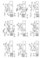
- the feeding toothing 27 in turn comprises six feeding teeth 28 which, as shown in Figs. 17 and 18, have a width substantially equal to the added widths of the initiation teeth 30 and entraining teeth 32. Furthermore, each tooth has an inclined side 28a (Fig. 5) disposed parallelly to sides 30a and 32a of teeth 30 and 32.
- a series of grooves 33 are also provided on the disk 15 which are each oriented according to a generatrix of the disk itself and spaced apart according to a pitch identical with that of the feeding teeth 28. Said grooves are designed to be selectively engaged, as more clearly explained in the following, by at least a stop member 34 housed in an annular support 35 fastened to the underneath of the support plate 8.
- the stop member 34 is slidably engaged in a housing located on the annular support 35 and elastically urged against the disk 15 by a compression spring 36 accommodated in the housing itself.
- the control unit is also provided to be interlocked to a device for measuring the thickness of the plate strip 4, as the latter moves forward in the direction of the press. In a preferred embodiment such a device is of the induction type.
- the press ram in its reciprocating motion entrains the parts connected thereto,i.e. the covering plates 9, the support and guide plates 8 and 5, as well as the entraining collar 25, the disk 15 and the parts engaged therewith.
- the parts connected to the bed 2, i.e. the die 3, posts 13, crosspiece 11 and initiation collar 23, remain stationary.
- disk 15 When punch 7 has to hold its rest position, disk 15, urged by the spring 17 is provided to maintain its feeding teeth 28 in abutment against the lower surface 25a of the entraining collar 25,each tooth having its side 28a close to the side 32a of the adjacente tooth 32 (see Fig. 5).
- each feeding tooth 28 engages between the two first initiation teeth 30. So while the ram, at its top dead center, reverse its movement, the disk 15 is retained by the initiation collar 23 and the punch is arranged so that it can reach its operative position, as clearly shown in Fig. 15. At the same time the offsetting existing between the entraining teeth 32 and initiation teeth 30 causes a further rotation of disk 15 as a result of the slidable engagement between sides 28a and 30a of the feeding and initiation teeth 28 and 30 respectively.
- the feeding tooth 28 is arranged to be engaged, at the following ram descent, between two adjoining entraining teeth 32, as shown in Fig. 9.
- the upper end of tooth 28 is in abutment against the bottom 32c.
- the disk 15 is disposed (see Fig.16) in a position to which corresponds the penetration of punch 7 into the plate strip 4.
- tooth 28 abuts against the side 30a of the last initation tooth in the corresponding group (see Fig. 12), which involves a new rotation of disk 15 which is again disposed in abutment against the surface 25a of the entraining collar.25.
- the present invention attains the intended purposes.
- the device in question allows presses on which it is mounted to be used at their maximum safety speed, which is now in the range of 600 blows per minute.
- the measuring device associated with the control unit allows the obtention of packs falling within the size tolerances even when the plate strip 4 is subjected to important thickness variations over the all length thereof. This is due to the fact that, by virtue of this device, the formation of the packs is carried out taking into account the thicknesses of the single laminations and not, as it occurs in other applications, by counting the ram blows or the number of the packed laminations.
- the device as conceived is susceptible of many modifications and variations, all falling within the inventive idea characterizing it. It is particularly pointed out that the initiation, entraining and feeding toothings can be composed of any number of teeth disposed in any manner, depending upon the characteristics of the operative cycle it is wished to obtain. Attention is also drawn to the fact that the device in question can be mounted on any type of press.
Landscapes
- Engineering & Computer Science (AREA)
- Mechanical Engineering (AREA)
- Manufacturing & Machinery (AREA)
- Power Engineering (AREA)
- Press Drives And Press Lines (AREA)
Applications Claiming Priority (2)
| Application Number | Priority Date | Filing Date | Title |
|---|---|---|---|
| IT19589/86A IT1190072B (it) | 1986-02-28 | 1986-02-28 | Dispositivo per l'azionamento periodico di uno o piu' punzioni in una pressa |
| IT1958986 | 1986-02-28 |
Publications (2)
| Publication Number | Publication Date |
|---|---|
| EP0235100A2 true EP0235100A2 (de) | 1987-09-02 |
| EP0235100A3 EP0235100A3 (de) | 1990-02-14 |
Family
ID=11159275
Family Applications (1)
| Application Number | Title | Priority Date | Filing Date |
|---|---|---|---|
| EP87830070A Withdrawn EP0235100A3 (de) | 1986-02-28 | 1987-02-27 | Vorrichtung zum periodischen Betätigen eines oder mehrerer Stempel in einer Presse |
Country Status (2)
| Country | Link |
|---|---|
| EP (1) | EP0235100A3 (de) |
| IT (1) | IT1190072B (de) |
Cited By (3)
| Publication number | Priority date | Publication date | Assignee | Title |
|---|---|---|---|---|
| FR2639281A1 (fr) * | 1988-11-18 | 1990-05-25 | Amada Co Ltd | Poinconneuse a tourelles |
| CN109742915A (zh) * | 2019-01-31 | 2019-05-10 | 重庆昆旺电子有限责任公司 | 电机上机壳组件装配设备 |
| CN114178382A (zh) * | 2022-01-10 | 2022-03-15 | 重庆特发信息光缆有限公司 | 一种冲压装置 |
Family Cites Families (2)
| Publication number | Priority date | Publication date | Assignee | Title |
|---|---|---|---|---|
| DE611280C (de) * | 1933-10-06 | 1935-03-25 | Stocko Metallwarenfabriken G M | Automatisch ausschaltbarer Einzelstempel in kombinierten Stanzwerkzeugen |
| DE2741537A1 (de) * | 1977-09-15 | 1979-03-22 | Cis Metalform Masch | Verfahren zur herstellung von teilen |
-
1986
- 1986-02-28 IT IT19589/86A patent/IT1190072B/it active
-
1987
- 1987-02-27 EP EP87830070A patent/EP0235100A3/de not_active Withdrawn
Cited By (9)
| Publication number | Priority date | Publication date | Assignee | Title |
|---|---|---|---|---|
| FR2639281A1 (fr) * | 1988-11-18 | 1990-05-25 | Amada Co Ltd | Poinconneuse a tourelles |
| WO1990005601A1 (en) * | 1988-11-18 | 1990-05-31 | Amada Company, Limited | Turret punch press |
| GB2240296A (en) * | 1988-11-18 | 1991-07-31 | Amada Co Ltd | Turrent punch press |
| US5119666A (en) * | 1988-11-18 | 1992-06-09 | Amada Company, Limited | Turret punch press |
| GB2240296B (en) * | 1988-11-18 | 1993-02-24 | Amada Co Ltd | Turrent punch press |
| AT400823B (de) * | 1988-11-18 | 1996-03-25 | Amada Co Ltd | Revolverstanzpresse und verfahren zum positionieren von stempeln in einer revolverstanzpresse |
| CN109742915A (zh) * | 2019-01-31 | 2019-05-10 | 重庆昆旺电子有限责任公司 | 电机上机壳组件装配设备 |
| CN109742915B (zh) * | 2019-01-31 | 2023-10-20 | 重庆昆旺电子有限责任公司 | 电机上机壳组件装配设备 |
| CN114178382A (zh) * | 2022-01-10 | 2022-03-15 | 重庆特发信息光缆有限公司 | 一种冲压装置 |
Also Published As
| Publication number | Publication date |
|---|---|
| IT8619589A1 (it) | 1987-08-28 |
| EP0235100A3 (de) | 1990-02-14 |
| IT8619589A0 (it) | 1986-02-28 |
| IT1190072B (it) | 1988-02-10 |
Similar Documents
| Publication | Publication Date | Title |
|---|---|---|
| US4108031A (en) | Aligning and stacking arrangement | |
| GB2174635A (en) | Punching machine | |
| EP0235100A2 (de) | Vorrichtung zum periodischen Betätigen eines oder mehrerer Stempel in einer Presse | |
| CN115945567A (zh) | 汽车座椅滑轨多工位一次性冲压成型装置 | |
| CN108097797B (zh) | 一种电动机安装壳制备方法 | |
| CN208913049U (zh) | 多工位环锻件制坯液压机 | |
| JPH0899255A (ja) | 順送り加工装置 | |
| CN214078957U (zh) | 一种抱箍自动弯折机 | |
| CN116979768B (zh) | 一种异形转子铁芯组装设备及其使用方法 | |
| CN113695484A (zh) | 一种双涡卷簧成型装置及方法 | |
| CN109365642B (zh) | 冲压侧翻边模具 | |
| US5749279A (en) | Hydraulic punch actuator with centering apparatus | |
| US4406148A (en) | Multi-station transfer press having transfer slide safety release means | |
| CN116550839A (zh) | 一种金属薄板的冲压装置及其使用方法 | |
| US5775104A (en) | Hydraulic apparatus for actuating a punch for a clutch facing machine | |
| CN222246280U (zh) | 一种连续压片机的智能控制装置 | |
| CN112845827A (zh) | 一种用于冲压设备的往复式冲孔装置 | |
| CN111822643A (zh) | 一种双边自动摆钉机构 | |
| US5048412A (en) | Apparatus for processing semiconductor packages and the like | |
| CN222403288U (zh) | 一种单头撞钉机 | |
| SU774955A1 (ru) | Механический пресс | |
| CN215149974U (zh) | 一种绿色环保的板材制备用压板装置 | |
| CN223748356U (zh) | 一种多孔洞模具切换的沉头孔连续挤压冲压机构 | |
| CN118455369B (zh) | 一种钣金定距冲孔切断机构 | |
| CN223916466U (zh) | 一种冲压机连续上料装置 |
Legal Events
| Date | Code | Title | Description |
|---|---|---|---|
| PUAI | Public reference made under article 153(3) epc to a published international application that has entered the european phase |
Free format text: ORIGINAL CODE: 0009012 |
|
| AK | Designated contracting states |
Kind code of ref document: A2 Designated state(s): AT BE CH DE ES FR GB GR LI LU NL SE |
|
| PUAL | Search report despatched |
Free format text: ORIGINAL CODE: 0009013 |
|
| AK | Designated contracting states |
Kind code of ref document: A3 Designated state(s): AT BE CH DE ES FR GB GR LI LU NL SE |
|
| STAA | Information on the status of an ep patent application or granted ep patent |
Free format text: STATUS: THE APPLICATION IS DEEMED TO BE WITHDRAWN |
|
| 18D | Application deemed to be withdrawn |
Effective date: 19900815 |
|
| RIN1 | Information on inventor provided before grant (corrected) |
Inventor name: GUSSONI, OLIVIERO |