EP0235672A2 - Durchlaufofen - Google Patents
Durchlaufofen Download PDFInfo
- Publication number
- EP0235672A2 EP0235672A2 EP87102267A EP87102267A EP0235672A2 EP 0235672 A2 EP0235672 A2 EP 0235672A2 EP 87102267 A EP87102267 A EP 87102267A EP 87102267 A EP87102267 A EP 87102267A EP 0235672 A2 EP0235672 A2 EP 0235672A2
- Authority
- EP
- European Patent Office
- Prior art keywords
- workpieces
- furnace
- conveyor belt
- switch
- cooling
- Prior art date
- Legal status (The legal status is an assumption and is not a legal conclusion. Google has not performed a legal analysis and makes no representation as to the accuracy of the status listed.)
- Granted
Links
- 230000005484 gravity Effects 0.000 claims abstract description 5
- 238000001816 cooling Methods 0.000 claims description 31
- 230000001681 protective effect Effects 0.000 claims description 9
- 238000010438 heat treatment Methods 0.000 claims description 5
- 230000007704 transition Effects 0.000 claims description 3
- 238000000034 method Methods 0.000 description 6
- QIQXTHQIDYTFRH-UHFFFAOYSA-N octadecanoic acid Chemical compound CCCCCCCCCCCCCCCCCC(O)=O QIQXTHQIDYTFRH-UHFFFAOYSA-N 0.000 description 5
- 238000005245 sintering Methods 0.000 description 4
- 238000012546 transfer Methods 0.000 description 3
- 238000004519 manufacturing process Methods 0.000 description 2
- 238000012856 packing Methods 0.000 description 2
- 238000012545 processing Methods 0.000 description 2
- 238000000137 annealing Methods 0.000 description 1
- 238000013459 approach Methods 0.000 description 1
- 230000015572 biosynthetic process Effects 0.000 description 1
- 238000010276 construction Methods 0.000 description 1
- 238000004320 controlled atmosphere Methods 0.000 description 1
- 238000003754 machining Methods 0.000 description 1
- 230000001105 regulatory effect Effects 0.000 description 1
- 238000005476 soldering Methods 0.000 description 1
- 239000007787 solid Substances 0.000 description 1
Images


Classifications
-
- F—MECHANICAL ENGINEERING; LIGHTING; HEATING; WEAPONS; BLASTING
- F27—FURNACES; KILNS; OVENS; RETORTS
- F27B—FURNACES, KILNS, OVENS OR RETORTS IN GENERAL; OPEN SINTERING OR LIKE APPARATUS
- F27B9/00—Furnaces through which the charge is moved mechanically, e.g. of tunnel type; Similar furnaces in which the charge moves by gravity
- F27B9/14—Furnaces through which the charge is moved mechanically, e.g. of tunnel type; Similar furnaces in which the charge moves by gravity characterised by the path of the charge during treatment; characterised by the means by which the charge is moved during treatment
- F27B9/20—Furnaces through which the charge is moved mechanically, e.g. of tunnel type; Similar furnaces in which the charge moves by gravity characterised by the path of the charge during treatment; characterised by the means by which the charge is moved during treatment the charge moving in a substantially straight path
- F27B9/24—Furnaces through which the charge is moved mechanically, e.g. of tunnel type; Similar furnaces in which the charge moves by gravity characterised by the path of the charge during treatment; characterised by the means by which the charge is moved during treatment the charge moving in a substantially straight path being carried by a conveyor
- F27B9/243—Endless-strand conveyor
-
- F—MECHANICAL ENGINEERING; LIGHTING; HEATING; WEAPONS; BLASTING
- F27—FURNACES; KILNS; OVENS; RETORTS
- F27B—FURNACES, KILNS, OVENS OR RETORTS IN GENERAL; OPEN SINTERING OR LIKE APPARATUS
- F27B9/00—Furnaces through which the charge is moved mechanically, e.g. of tunnel type; Similar furnaces in which the charge moves by gravity
- F27B9/02—Furnaces through which the charge is moved mechanically, e.g. of tunnel type; Similar furnaces in which the charge moves by gravity of multiple-track type; of multiple-chamber type; Combinations of furnaces
- F27B9/021—Furnaces through which the charge is moved mechanically, e.g. of tunnel type; Similar furnaces in which the charge moves by gravity of multiple-track type; of multiple-chamber type; Combinations of furnaces having two or more parallel tracks
- F27B9/022—With two tracks moving in opposite directions
- F27B9/023—With two tracks moving in opposite directions with a U turn at one end
-
- F—MECHANICAL ENGINEERING; LIGHTING; HEATING; WEAPONS; BLASTING
- F27—FURNACES; KILNS; OVENS; RETORTS
- F27B—FURNACES, KILNS, OVENS OR RETORTS IN GENERAL; OPEN SINTERING OR LIKE APPARATUS
- F27B9/00—Furnaces through which the charge is moved mechanically, e.g. of tunnel type; Similar furnaces in which the charge moves by gravity
- F27B9/14—Furnaces through which the charge is moved mechanically, e.g. of tunnel type; Similar furnaces in which the charge moves by gravity characterised by the path of the charge during treatment; characterised by the means by which the charge is moved during treatment
- F27B9/147—Furnaces through which the charge is moved mechanically, e.g. of tunnel type; Similar furnaces in which the charge moves by gravity characterised by the path of the charge during treatment; characterised by the means by which the charge is moved during treatment the charge moving on an inclined floor
Definitions
- the invention relates to a continuous furnace with a furnace part for heating the workpieces, a cooling part for the subsequent cooling of the workpieces and a conveyor belt which conveys workpieces through the furnace part and the cooling part to a first delivery station, a second delivery station for removing workpieces from the Oven part is provided.
- a conveyor belt continuous furnace is known as it is used for the heat treatment of sintered parts.
- These continuous furnaces are designed so that the sintered parts are conveyed from a feed station into a furnace part by means of a conveyor belt, in which they successively pass through a so-called stearate zone, which serves to evaporate the stearate present in the sintered parts, and then pass through a so-called sintering zone in which actual sintering process takes place.
- the sintered parts reach a temperature of approx. 1100 ° C.
- a cooling part with an elongated cooling zone then adjoins the furnace part of the continuous furnace, in which the sintered parts are brought back to room temperature.
- the sintered parts can then be removed from a delivery station of the conveyor belt. The entire process from the feed station to the discharge station takes place in a protective gas atmosphere.
- Such a second delivery station is used to transfer sintered parts that have just left the furnace part and are still at an operating temperature of, for example, 1100 ° C. located, can be removed immediately and can be fed to a further processing station, for example a press, in the operationally warm state.
- the invention is therefore based on the object of developing a continuous furnace of the type mentioned in such a way that removal of the warm workpieces in or at the end of the furnace part is possible without manual removal tools, so that the production process takes place more regularly, so that it is less prone to failure and can be automated.
- This object is achieved in that a switch is provided between the furnace part and the cooling part, via which the workpieces either get to the cooling part with the adjoining first delivery station or directly to the second delivery station under the influence of gravity.
- the object on which the invention is based is thus completely achieved because the switch can be adjusted with optional access, so that the workpieces, for example the sintered parts, under the influence of gravity either the first delivery position. for example at the end of a cooling zone downstream of the furnace part of a cooling part or else the second delivery station, for example for transfer to a press or the like. Because the workpieces only find their way through the switch under the influence of gravity, complicated adjustment devices, such as are difficult to use at points of high operating temperatures, are not necessary.
- the switch is arranged at the lower end of a slide connected to the end of the furnace part and comprises differently oriented track sections, in particular a curve section, and a straight section, which can optionally be connected to the end of the slide.
- This measure has the advantage that the workpieces arrive directly from the conveyor, for example a conveyor belt, on a fixed element, namely the slide, while the actual switch is only at the end of the slide, which moves the workpieces into one or the other Directs direction.
- the moving parts are thus already at a certain distance from the areas of the furnace part which are at a high operating temperature, so that the system as a whole is less susceptible to faults.
- the switch itself is designed as a slide at the end of the furnace part, two guide plates butt-jointed in a T-shape and pivotally arranged such that in one pivot position the workpieces via the one guide plate to the first delivery station and in the the other swivel position, slide the workpieces over the other guide plate to the second delivery station.
- the switch designed as a slide is somewhat closer to the warm part of the furnace, but due to the extremely simple construction of the switch, trouble-free operation is also ensured in this case.
- the formation of the switch provided in this exemplary embodiment is advantageous for the applications in which the first and the second delivery station are in mutually opposite positions.
- the continuous furnace according to the invention can be used with particular advantage if the workpieces are sintered parts and the furnace part and the cooling part are designed to be inert gas-tight.
- the transition from the end of the conveying device of the furnace part to the beginning of the conveying device of the cooling part is designed as an inert gas-tight channel.
- the continuous furnace according to the invention can be designed such that the workpieces are arranged on the conveyor device on lines inclined to the conveying direction.
- This measure has the advantage that the workpieces individually approach the front transfer edge at the end of the conveyor, so that despite the high packing density on the conveyor, for example on the conveyor belt, the workpieces are separated by successively reaching the slide, for example.
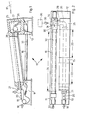
- FIGS. 1 and 2 are a total of a conveyor belt continuous furnace, as can be used for hard and high-temperature soldering, bright annealing and hardening under a controlled atmosphere with a continuous machining process.
- the facilities for heating, regulating, supplying and removing protective gas and the like are known per se and are not shown in FIGS. 1 and 2 for the sake of clarity.
- FIG. 1 and 2 show a furnace part 15 and a cooling part 16 spatially separated therefrom, which extends next to the furnace part 15 parallel to the latter.
- Fig. 1 shows that the furnace part 15 is designed to rise slightly in the conveying direction, the angle of rise 17 preferably being approximately 10 °.
- a feed station for sintered parts 19 is indicated at 18, which are placed there on a first conveyor belt 20.
- the first conveyor belt 20 arrives at an entrance 21 of the furnace part 15 with a slight increase corresponding to the angle 17, where it first passes through a stearate zone 22 indicated in FIG. 2 and then through a sintering zone 23.
- the sintered parts 19 now fall over an edge of a transport roller 28 forming the end of the first conveyor belt 20 in the direction of an arrow 27 onto a chute 26 which extends within a gas-tight channel 29 to the cooling part 16.
- the slide 26 ends there in a switch 30 designed as a slide, which ver in Fig. 2 in the horizontal direction is slidably arranged.
- the chute 26 opens into a curve piece 31 of the switch 30, so that the sintered parts 19 reach a second conveyor belt 32 of the cooling part 16.
- the sintered parts 19 can finally be removed at a first delivery station 33 at the end of the second conveyor belt 32.
- the slide 26 opens into a straight piece 34 of the switch 30 and the sintered parts 19 slide through the switch 30 into a second delivery station 35, which for example can lead to a press 36.
- the mode of operation of the conveyor belt continuous furnace 10 according to FIGS. 1 and 2 is as follows:
- the sintered parts 19 are placed on the first conveyor belt 20 at the feed station 18 and pass through the heated furnace part 15 with its stearate zone 22, in which the stearate of the sintered parts 19 is evaporated and its sintered zone 23.
- the furnace part 15 is filled with hot protective gas by the heating process , this hot protective gas tends to rise so that the point of highest temperature is in the region of the end chamber 25.
- the end chamber 25 is encapsulated upwards and there is only an exit downward via the chute 26, the heated protective gas cannot escape from the end chamber 25, which leads to particularly low heat losses.
- the switch 30 When treating sintered parts 19 which are subsequently, i.e. in the still warm state, to be further processed on the press 36, the switch 30 is in the position not shown in FIG. 2 and the incoming sintered parts 19 slip directly to the press 36.
- Fig. 3 shows, on a greatly enlarged scale, a plan view of the first conveyor belt 20 in the region of the transport roller 28. It can be seen that the sintered parts 19 are arranged along lines 40 which are inclined to the conveying direction, for example at 45 °. In this way it is ensured that, despite the relatively high packing density on the first conveyor belt 20, the sintered parts 19 fall successively over the outer edge of the transport roller 28 onto the chute 26. 3 that a sintered part 19a has already slipped over the edge of the transport roller 28, the sintered parts 19b, then 19c and then 19d will follow one after the other and so on.
- the sintered parts 19, 19a, 19b, 19c, 19d ... will appear isolated so that a decision can be made from sintered part to sintered part as to whether the switch 30 should be turned over or not.
- FIGS. 1 and 2 show a further, highly schematic embodiment of a conveyor belt continuous furnace according to the invention.
- 15 'and 16' are again indicated furnace part and cooling part and it can be seen that the furnace part 15 'runs horizontally, but above the cooling part 16'.
- the gas-tight channel 29 ' is in turn arranged at a position corresponding to FIGS. 1 and 2.
- the feed station 18 'and the first discharge station 33' are one above the other in this embodiment.
- the cooling part 16' can also be angled differently, that is, it does not necessarily have to extend parallel below the furnace part 15 '.
- the furnace part 15 ′′ again runs horizontally, the transition to the cooling part 16 ′′ is again made via a gas-tight channel 29 ′′, the cooling part 16 ′′ However, it rises in the conveying direction, so that the feed station 18 ′′ and the first discharge station 33 ′′ are again at the same height.
- FIG. 6 shows a variant with a differently designed switch 50 in a partially broken representation similar to FIG. 1.
- the end of the first conveyor belt 20 represented by the transport roller 28 is initially arranged obliquely above the start of the second conveyor belt 32a, but the second conveyor belt 32a is not arranged parallel and in the opposite direction to the first conveyor belt 20, as is the case in the exemplary embodiments of FIG 1, 2, 4 and 5 was the case, the second conveyor belt 32a is rather arranged in the front extension of the first conveyor belt 20, be it in a straight line or in an angled arrangement, depending on the available space conditions.
- the switch 50 is arranged obliquely below the transport roller 28 and specifically in the direction of the second conveyor belt 32a, the mode of operation of which can be seen in detail in FIG. 7.
- the switch 50 has a first guide plate 51 which can be rotated about a first spatially fixed axis 52. At a distance from the first axis 52 there is a second axis 53 on the first guide plate 51, to which a second guide plate 54 is articulated. The opposite free end of the second guide plate 54 slides, for example, on a base, which is indicated in FIG. 7 with 55.
- the switch 50 is now flipped, it reaches the position shown in dashed lines, in which the first guide plate 51 has been pivoted away from the path of movement of the sintered part 19 sliding down, so that the sintered part 19 reaches the surface of the now exposed second guide plate 54.
- the sintered part 19 now slides on the second guide plate 54 between the transport roller 28 and the second conveyor belt 32 to a second delivery station, indicated in FIG. 6 by 35a, which in turn can lead to a press or the like.
Landscapes
- Engineering & Computer Science (AREA)
- Mechanical Engineering (AREA)
- General Engineering & Computer Science (AREA)
- Tunnel Furnaces (AREA)
- Powder Metallurgy (AREA)
- Filters For Electric Vacuum Cleaners (AREA)
- Glass Compositions (AREA)
- Filtering Materials (AREA)
- Crystals, And After-Treatments Of Crystals (AREA)
- Liquid Deposition Of Substances Of Which Semiconductor Devices Are Composed (AREA)
- Iron Core Of Rotating Electric Machines (AREA)
Abstract
Description
- Die Erfindung betrifft einen Durchlaufofen mit einem Ofenteil zum Wärmen der Werkstücke, einen Kühlteil zum anschließenden Abkühlen der Werkstücke und einem Förderband, das Werkstücke durch den Ofenteil und den Kühlteil hindurch zu einer ersten Abgabestation hin fördert, wobei eine zweite Abgabestation zur Entnahme von Werkstücken aus dem Ofenteil vorgesehen ist.
- Aus der DE-AS 26 01 658 ist ein Förderband-Durchlaufofen bekannt, wie er zur Wärmebehandlung von Sinterteilen verwendet wird. Diese Durchlauföfen sind so ausgebildet,-daß die Sinterteile von einer Aufgabestation mittels eines Förderbandes in einen Ofenteil gefördert werden, in dem sie nacheinander eine sogenannte Stearatzone, die zum Verdampfen des in den Sinterteilen vorhandenen Stearats dient und dann eine sogenannte Sinterzone durchlaufen, in der der eigentliche Sinterprozeß stattfindet. In der Sinterzone nehmen die Sinterteile eine Temperatur von ca. 1100°C an. Üblicherweise schließt sich an den Ofenteil des Durchlaufofens dann ein Kühlteil mit einer langgestreckten Kühlzone an, in der die Sinterteile wieder auf Raumtemperatur gebracht werden. Am Ende des Kühlteils können die Sinterteile dann von einer Abgabestation des Förderbandes wieder entnommen werden. Der gesamte Prozeß von der Aufgabestation bis zur Abgabestation spielt sich dabei abgeschlossen unter Schutzgasatmosphäre ab.
- Es ist bekannt, derartige Öfen dadurch zu modifizieren, daß man am Ende des Ofenteils eine seitliche Eingriffsmöglichkeit in den Ofen, d.h. eine zweite Abgabestation, schafft. Diese Abgabestation weist dabei eine verschließbare Klappe auf, um die Schutzgasatmosphäre im Ofen nicht zu stören, solange kein Eingriff erfolgt.
- Eine solche zweite Abgabestation wird dazu verwendet, um Sinterteile, die gerade den Ofenteil verlassen haben und sich noch auf Betriebstemperatur von beispielsweise 1100° C befinden, unmittelbar entnehmen und im betriebswarmen Zustand einer weiteren Bearbeitungsstation, beispielsweise einer Presse, zuführen zu können.
- Hierzu hat man sich bislang rein manueller Methoden bedient, indem ein Arbeiter die Klappe der zweiten Abgabestation öffnete und dann mittels-geeigneter wärmebeständiger Greifwerkzeuge die betriebswarmen Sinterteile vom Förderbnad entnahm und dann entweder auf eine andere Fördereinrichtung umsetzte oder direkt der weiteren Bearbeitungsstation zuführte. Die nicht entnommenen Sinterteile passieren in diesem Falle die zweite Abgabestation und werden in der eingangs beschriebenen Weise in der Kühlzone des Kühlteils wieder auf Raumtemperatur gebracht, sodaß sie entweder anderweitigen Zwecken zugeführt oder erneut durch Durchlaufen des Ofenteils auf Betriebstemperatur gebracht werden können.
- Es liegt auf der Hand, daß diese bekannte Vorgehensweise zum seitlichen Entnehmen von Sinterteilen am Ende des Ofenteiles sehr umständlich ist, Arbeitskraft bindet und keine automatisierten Fertigungsvorgänge gestattet.
- Der Erfindung liegt daher die Aufgabe zugrunde, einen Durchlaufofen der eingangs genannten Art dahingehend weiterzubilden, daß eine Entnahme der betriebswarmen Werkstücke im oder am Ende des Ofenteils ohne manuell zu handhabende Entnahmewerkzeuge möglich ist, so daß der Fertigungsvorgang regelmäßiger, damit weniger störungsanfällig und automatisierbar erfolgt.
- Diese Aufgabe wird erfindungsgemäß dadurch gelöst, daß zwischen Ofenteil und Kühlteil eine Weiche vorgesehen ist, über die die Werkstücke unter Schwerkrafteinfluß wahlweise entweder zum Kühlteil mit daran anschließender erster Abgabestation oder direkt zur zweiten Abgabestation gelangen.
- Die der Erfindung zugrundeliegende Aufgabe wird damit vollkommen gelöst, weil mit wahlweisem Zugriff die Weiche verstellt werden kann, sodaß die Werkstücke, beispielsweise die Sinterteile, unter Schwerkrafteinfluß entweder der ersten Abgabestatian,. beispielsweise am Ende einer dem Ofenteil nachgeschalteten Kühlzone eines Kühlteils oder aber der zweiten Abgabestation beispielsweise zum Umsetzen auf eine Presse oder dergleichen zugeführt werden können. Dadurch, daß die Werkstücke nur unter Schwerkrafteinfluß ihren Weg durch die Weiche nehmen, sind komplizierte Verstelleinrichtungen, wie sie an Punkten hoher Betriebstemperaturen nur mit großen Schwierigkeiten einzusetzen sind, nicht erforderlich.
- Bei einer bevorzugten Ausgestaltung der Erfindung ist die Weiche am unteren Ende einer an das Ende des Ofenteils angeschlossenen Rutsche angeordnet und umfaßt unterschiedlich gerichtete Bahnstücke, insbesondere ein Kurvenstück, sowie ein Geradenstück, die wahlweise an das Ende der Rutsche anschließbar sind.
- Diese Maßnahme hat den Vorteil, daß die Werkstücke unmittelbar von der Fördereinrichtung, beispielsweise einem Förderband, auf ein raumfestes Element, nämlich die Rutsche gelangen, während sich erst am Ende der Rutsche die eigentliche Weiche befindet, die die Werkstücke in die eine oder andere Richtung lenkt. Die beweglichen Teile befinden sich somit bereits in einem gewissen Abstand von den auf hoher Betriebstemperatur liegenden Bereichen des Ofenteils, sodaß die Anlage insgesamt wenig störanfällig ist.
- Bei einer anderen Ausgestaltung der Erfindung ist die Weiche selbst als Rutsche am Ende des Ofenteils ausgebildet, wobei zwei Leitbleche T-förmig stumpf miteinander verbunden und derart schwenkbar angeordnet sind, daß in der einen Schwenkstellung die Werkstücke über das eine Leitblech zur ersten Abgabestation und in der anderen Schwenkstellung die Werkstücke über das andere Leitblech zur zweiten Abgabestation rutschen.
- Zwar befindet sich bei diesem Ausführungsbeispiel der Erfindung die als Rutsche ausgebildete Weiche in etwas größerer Nähe zum betriebswarmen Teil des Ofens, aufgrund der extrem einfachen Konstruktion der Weiche ist jedoch auch in diesem Falle ein störungsfreier Betrieb gewährleistet. Von Vorteil ist die bei diesem Ausführungsbeispiel vorgesehene Ausbildung der Weiche für die Anwendungsfälle, bei denen sich die erste und die zweite Abgabestation in einander gegenüberliegenden Positionen befinden.
- Wie bereits eingangs angedeutet, kann der erfindungsgemäße Durchlaufofen mit besonderem Vorteil dann eingesetzt werden, wenn die Werkstücke Sinterteile sind und der Ofenteil sowie der Kühlteil schutzgasdicht ausgebildet sind.
- In diesem Falle ist es besonders bevorzugt, wenn der Übergang vom Ende der Fördereinrichtung des Ofenteils zum Anfang der Fördereinrichtung des Kühlteils als schutzgasdichter Kanal ausgebildet ist.
- Dies hat nämlich den Vorteil, daß die Weiche, gegebenenfalls mit Rutsche, im schutzgasdichten Kanal angeordnet sein kann, sodaß der gesamte Umlenkvorgang in der Weiche ebenfalls unter Schutzgasatmosphäre stattfindet.
- Schließlich kann mit weiterem Vorteil der erfindungsgemäße Durchlaufofen so ausgebildet sein, daß die Werkstücke auf der Fördereinrichtung auf zur Förderrichtung geneigten Linien angeordnet sind.
- Diese Maßnahme hat den Vorteil, daß die Werkstücke sich einzeln der vorderen Übergabekante am Ende der Fördereinrichtung nähern, sodaß trotz großer Packungsdichte auf der Fördereinrichtung, beispielsweise am Förderband, die Werkstücke dadurch vereinzelt werden, daß sie nacheinander beispielsweise auf die Rutsche gelangen.
- Weitere Vorteile ergeben sich aus der Beschreibung und der beigefügten Zeichnung.
- Ausführungsbeispiele der Erfindung sind in der Zeichnung dargestellt und werden in der nachfolgenden Beschreibung näher erläutert. Es zeigen:
- Fig. 1
- und 2 eine Seitenansicht und eine Draufsicht, teilweise aufgebrochen, eines Ausführungsbeispiels eines erfindungsgemäßen Durchlaufofens;
- Fig. 3 -eine Draufsicht auf ein erfindungsgemäß bestücktes Förderband, in stark vergrößertem Maßstab;
- Fig. 4
- und 5 weitere stark schematisierte und verkleinerte Ansichten weiterer Ausführungsbeispiele erfindungsgemäßer Durchlauföfen;
- Fig. 6 eine Darstellung eines weiteren Ausführungsbeispiels, ähnlich Fig. 1, jedoch teilweise abgebrochen, zur Veranschaulichung der Funktionsweise einer Ausführungsform einer Weiche;
- Fig. 7 einen stark vergrößerten Ausschnitt aus Fig. 6 zur Erläuterung der dort dargestellten Weiche.
- In Fig. 1 ist 10 insgesamt ein Förderband-Durchlaufofen, wie er zum Hart- und Hochtemperaturlöten, Blankglühen und Härten unter kontrollierter Atmosphäre mit kontinuierlichem Bearbeitungsprozess eingesetzt werden kann. Die Einrichtungen zum Heizen, Regeln, Zu- und Abführen von Schutzgas und dgl. sind an sich bekannt und der Übersichtlichkeit halber in den Fig. 1 und 2 nicht dargestellt.
- Man erkennt in den Fig. 1 und 2 einen Ofenteil 15 sowie einen räumlich davon getrennten Kühlteil 16, der sich neben dem 0fenteil 15 parallel zu diesem erstreckt.
- Fig. 1 zeigt, daß der Ofenteil 15 in Förderrichtung leicht ansteigend ausgebildet ist, wobei der Anstiegswinkel 17 vorzugsweise etwa 10° beträgt.
- Am Anfang des 0fenteiles 15 ist mit 18 eine Aufgabestation für Sinterteile 19 angedeutet, die dort auf ein erstes Förderband 20 aufgesetzt werden. Das erste Förderband 20 gelangt unter leichtem Anstieg entsprechend dem Winkel 17 in einen Eingang 21 des Ofenteils 15, durchläuft dort in an sich bekannter Weise zunächst eine in Fig. 2 angedeutete Stearatzone 22 und alsdann eine Sinterzone 23.
- Schließlich gelangen die Sinterteile 19 auf dem ersten Förderband 20 in eine Endkammer 25, die sich am obersten Punkt des Ofenteils 15 befindet.
- Die Sinterteile 19 fallen nun über eine Kante einer das Ende des ersten Förderbandes 20 bildende Transportwalze 28 in Richtung eines Pfeiles 27 auf eine Rutsche 26, die sich innerhalb eines gasdichten Kanals 29 hinüber zum Kühlteil 16 erstreckt.
- Die Rutsche 26 mündet dort in einer als Schieber ausgebildeten Weiche 30, die in Fig. 2 in horizontaler Richtung verschiebbar angeordnet ist. In der in Fig. 2 eingezeichneten Stellung mündet die Rutsche 26 in ein Kurvenstück 31 der Weiche 30, so daß die Sinterteile 19 auf ein zweites Förderband 32 des Kühlteils 16 gelangen. Nach Durchlaufen einer Kühlzone 24 des Kühlteils 16 sind die Sinterteile 19 schließlich an einer ersten Abgabestation 33 am Ende des zweiten Förderbandes 32 abnehmbar.
- Wird die Weiche 30 hingegen in die in Fig. 2 nicht eingezeichneten Stellung durch Verschieben nach links umgelegt, so mündet die Rutsche 26 in ein Geradenstück 34 der Weiche 30 und die Sinterteile 19 rutschen durch die Weiche 30 durch in eine zweite Abgabestation 35, die beispielsweise zu einer Presse 36 führen kann.
- Die Wirkungsweise des Förderband-Durchlaufofens 10 gemäß den Fig. 1 und 2 ist wie folgt:
- Die Sinterteile 19 werden an der Aufgabestation 18 auf das erste Förderband 20 aufgesetzt und durchlaufen den aufgeheizten Ofenteil 15 mit seiner Stearatzone 22, in der das Stearat der Sinterteile 19 verdampft wird und seiner Sinterzone 23. Durch den Aufheizvorgang ist der Ofenteil 15 mit heißem Schutzgas gefüllt, wobei dieses heiße Schutzgas danach strebt, nach oben zu steigen, so daß der Punkt der höchsten Temperatur sich im Bereich der Endkammer 25 befindet. Da die Endkammer 25 jedoch nach oben gekapselt ist und nur nach unten über die Rutsche 26 ein Ausgang besteht, kann das erhitzte Schutzgas aus der Endkammer 25 nicht entweichen, was zu besonders geringen Wärmeverlusten führt.
- Wenn Sinterteile 19 behandelt werden, die anschließend, d.h. im noch warmen Zustand, auf der Presse 36 weiterbearbeitet werden sollen, so befindet sich die Weiche 30 in der in Fig. 2 nicht eingezeichneten Stellung und die ankommenden Sinterteile 19 rutschen unmittelbar zur Presse 36 durch.
- Wenn jedoch nun mehr Sinterteile 19 an der Presse 36 ankommen, als diese momentan verarbeiten kann, beispielsweise deswegen, weil das erste Förderband 20 mit zu vielen Sinterteilen 19 bestückt wurde oder weil sich aufgrund einer Störung im Bereich der Presse 36 ein Stau bildet, so wird die Weiche 30 in die in Fig. 2 eingezeichnete Stellung umgelegt und die momentan nicht benötigten warmen Sinterteile 19, die von der Rutsche 26 herkommen, gelangen auf das zweite Förderband 32 und werden behutsam abgekühlt. Sie können nun entweder anderweitig verwendet oder aber nochmals in einem erneuten Durchgang dem Ofenteil 15 zugeführt werden.
- Fig. 3 zeigt, in stark vergrößertem Maßstab, eine Draufsicht auf das erste Förderband 20 im Bereich der Transport walze 28. Man erkennt, daß die Sinterteile 19 entlang von Linien 40 angeordnet sind, die zur Förderrichtung geneigt verlaufen, beisielsweise unter 45°. Auf diese Weise wird sichergestellt, daß trotz relativ hoher Packungsdichte auf dem ersten Förderband 20 die Sinterteile 19 nacheinander über die äußere Kante der Transportwalze 28 auf die Rutsche 26 fallen. In Fig. 3 erkennt man, daß ein Sinterteil 19a bereits über die Kante der Transportwalze 28 her- übergerutscht ist, es werden nacheinander die Sinterteile 19b, dann 19c und dann 19d folgen und so fort.
- Am Ausgang der Weiche 30 werden daher die Sinterteile 19, 19a, 19b, 19c, 19d ... vereinzelt erscheinen, so daß von Sinterteil zu Sinterteil eine Entscheidung getroffen werden kann, ob die Weiche 30 umgelegt werden soll oder nicht.
- Fig. 4 zeigt ein weiteres, stark schematisiertes Ausführungsbeispiel eines erfindungsgemäßen Förderband-Durchlaufofens. Mit 15' und 16' sind wiederum Ofenteil und Kühlteil angedeutet und man erkennt, daß der Ofenteil 15' horizontal, jedoch oberalb des Kühlteils 16' verläuft. Der gasdichte Kanal 29' ist wiederum an einer Position entsprechend Fig. 1 und 2 angeordnet. Die Aufgabestation 18' und die erste Abgabestation 33' befinden sich bei diesem Ausführungsbeispiel übereinander. Schließlich ist mit 16a' angedeutet, daß das Kühlteil 16' auch anders abgewinkelt verlaufen kann, sich also nicht notwendigerweise parallel unterhalb des Ofenteils 15' erstrecken muß.
- In einer ähnlichen Darstellung, wie sie Fig. 5 zeigt, verläuft bei einem anderen Ausführungsbeispiel der Erfindung der Ofenteil 15'' wieder horizontal, der Übergang zu dem Kühlteil 16'' wird wiederum über einen gasdichten Kanal 29'' hergestellt, der Kühlteil 16" verläuft jedoch in Förderrichtung ansteigend, so daß sich die Aufgabestation 18'' und die erste Abgabestation 33'' wieder auf derselben Höhe befinden.
- Es versteht sich, daß die schematischen Darstellungen, wie sie die Fig. 4 und 5 zeigen, in entsprechender Variation noch weitergebildet werden können.
- Fig. 6 zeigt in teilweise abgebrochener Darstellung ähnlich Fig. 1 eine Variante mit einer anders ausgebildeten Weiche 50.
- Auch bei diesem Ausführungsbeispiel ist zunächst das durch die Transportwalze 28 dargestellte Ende des ersten Förderbandes 20 schräg über dem Anfang des zweiten Förderbandes 32a angeordnet, wobei jedoch das zweite Förderband 32a nicht parallel und gegenläufig zum ersten Förderband 20 angeordnet ist, wie es bei den Ausführungsbeispielen der Fig. 1, 2, 4 und 5 der Fall war, das zweite Förderband 32a ist vielmehr in vorderer Verlängerung des ersten Förderbandes 20 angeordnet, sei es in geradliniger, sei es in abgewinkelter Anordnung, je nach vorliegenden Raumverhältnissen.
- Schräg unterhalb der Transportwalze 28 und zwar in Richtung auf das zweite Förderband 32a hin ist die Weiche 50 angeordnet, deren Funktionsweise im einzelnen Fig. 7 zu entnehmen ist.
- Man erkennt aus Fig. 7, daß die Weiche 50 ein erstes Leitblech 51 aufweist, das um eine erste raumfeste Achse 52 drehbar ist. Etwas von der ersten Achse 52 beabstande< befindet sich am ersten Leitblech 51 eine zweite Achse 53, an der ein zweites Leitblech 54 angelenkt ist. Das gegenüberliegende freie Ende des zweiten Leitblechs 54 gleitet beispielsweise auf einem Untergrund, der in Fig. 7 mit 55 angedeutet ist.
- Bei der in Fig. 7 durchgezogen eingezeichneten Stellung der Weiche 50 gleiten vom ersten Förderband 20 abrutschende Sinterteile 19 auf das erste Leitblech 51, das die Sinterteile 19 auf das zweite Förderband 32a umlenkt. Die durchgezogen eingezeichnete Stellung der Weiche 50 in Fig. 7 entspricht somit funktional der in Fig. 2 eingezeichneten Stellung der dortigen Weiche 30.
- Wird nun jedoch die Weiche 50 umgelegt, gelangt sie in die gestrichelt eingezeichnete Stellung, in der das erste Leitblech 51 aus der Bewegungsbahn des herabrutschenden Sinterteiles 19 weggeschwenkt ist, so daß das Sinterteil 19 auf die Oberfläche des nun freiliegenden zweiten Leitbleches 54 gelangt. Auf dem zweiten Leitblech 54 gleitet nun das Sinterteil 19 zwischen der Transportwalze 28 und dem zweiten Förderband 32 hindurch zu einer in Fig. 6 mit 35a angedeuteten zweiten Abgabestation, die wiederum zu einer Presse oder dgl. führen kann.
Claims (7)
Priority Applications (1)
| Application Number | Priority Date | Filing Date | Title |
|---|---|---|---|
| AT87102267T ATE48695T1 (de) | 1986-02-22 | 1987-02-18 | Durchlaufofen. |
Applications Claiming Priority (2)
| Application Number | Priority Date | Filing Date | Title |
|---|---|---|---|
| DE3605725A DE3605725C1 (de) | 1986-02-22 | 1986-02-22 | Durchlaufofen |
| DE3605725 | 1986-02-22 |
Publications (3)
| Publication Number | Publication Date |
|---|---|
| EP0235672A2 true EP0235672A2 (de) | 1987-09-09 |
| EP0235672A3 EP0235672A3 (en) | 1987-12-23 |
| EP0235672B1 EP0235672B1 (de) | 1989-12-13 |
Family
ID=6294701
Family Applications (1)
| Application Number | Title | Priority Date | Filing Date |
|---|---|---|---|
| EP87102267A Expired EP0235672B1 (de) | 1986-02-22 | 1987-02-18 | Durchlaufofen |
Country Status (5)
| Country | Link |
|---|---|
| EP (1) | EP0235672B1 (de) |
| JP (2) | JPS62237279A (de) |
| AT (1) | ATE48695T1 (de) |
| DE (2) | DE3605725C1 (de) |
| ES (1) | ES2012463B3 (de) |
Cited By (1)
| Publication number | Priority date | Publication date | Assignee | Title |
|---|---|---|---|---|
| CN108562162A (zh) * | 2018-02-12 | 2018-09-21 | 西安中科麦特电子技术设备有限公司 | 用于双排传输隧道炉的光伏组件变速接驳系统 |
Family Cites Families (6)
| Publication number | Priority date | Publication date | Assignee | Title |
|---|---|---|---|---|
| DE730294C (de) * | 1940-12-24 | 1943-01-09 | Otto Junker Fa | Einseitig geschlossener Gluehofen mit endloser Foerdervorrichtung |
| DE2601658C3 (de) * | 1976-01-17 | 1978-11-30 | Fa. J.F. Mahler, 7300 Esslingen | Kühlvorrichtung für einen an der Ein- und Auslaßseite offenen Durchlaufofen zum Wärmebehandeln von Werkstücken |
| JPS6020444B2 (ja) * | 1982-01-12 | 1985-05-22 | マツダ株式会社 | 熱間鍛造品の焼もどし炉 |
| US4449923A (en) * | 1982-05-04 | 1984-05-22 | Chugai Ro Kogyo Co., Ltd. | Continuous heat-treating furnace |
| JPS5938583A (ja) * | 1982-08-27 | 1984-03-02 | 玉川機械株式会社 | ベルト式連続雰囲気炉 |
| DE3309206C2 (de) * | 1983-03-15 | 1986-12-18 | Müller KG Pumpen-Maschinen-Stahlbau-Bergwerks- und Industriebedarf, 4690 Herne | Übergabestation für Fließfördermittel des Untertagebetriebes |
-
1986
- 1986-02-22 DE DE3605725A patent/DE3605725C1/de not_active Expired
-
1987
- 1987-02-18 DE DE8787102267T patent/DE3761167D1/de not_active Expired - Lifetime
- 1987-02-18 ES ES87102267T patent/ES2012463B3/es not_active Expired - Lifetime
- 1987-02-18 AT AT87102267T patent/ATE48695T1/de active
- 1987-02-18 EP EP87102267A patent/EP0235672B1/de not_active Expired
- 1987-02-19 JP JP62034684A patent/JPS62237279A/ja active Pending
-
1988
- 1988-10-06 JP JP1988130508U patent/JPH038949Y2/ja not_active Expired
Cited By (1)
| Publication number | Priority date | Publication date | Assignee | Title |
|---|---|---|---|---|
| CN108562162A (zh) * | 2018-02-12 | 2018-09-21 | 西安中科麦特电子技术设备有限公司 | 用于双排传输隧道炉的光伏组件变速接驳系统 |
Also Published As
| Publication number | Publication date |
|---|---|
| EP0235672B1 (de) | 1989-12-13 |
| DE3605725C1 (de) | 1987-08-27 |
| DE3761167D1 (de) | 1990-01-18 |
| JPH0163995U (de) | 1989-04-25 |
| ES2012463B3 (es) | 1990-04-01 |
| JPH038949Y2 (de) | 1991-03-06 |
| JPS62237279A (ja) | 1987-10-17 |
| EP0235672A3 (en) | 1987-12-23 |
| ATE48695T1 (de) | 1989-12-15 |
Similar Documents
| Publication | Publication Date | Title |
|---|---|---|
| EP1834931B1 (de) | Verfahren und Vorrichtung zum Anschmelzen von Stangenenden | |
| EP2989220B1 (de) | Vorrichtung zum presshaerten von bauteilen | |
| DE19600479C2 (de) | Wärmebehandlungsanlage zum Lösungsglühen von Aluminium-Legierungsbauteilen in der Luftfahrtindustrie | |
| EP0010597B1 (de) | Zuführrinne für Stangen und Rohre | |
| DE2163268C3 (de) | Ofen zum Erwärmen von Glasplatten | |
| DE2907960A1 (de) | Verfahren und vorrichtung zum kontinuierlichen waermebehandeln von vereinzeltem, langgestrecktem metallischen gut | |
| EP0235672B1 (de) | Durchlaufofen | |
| WO2001027547A1 (de) | Verfahren und vorrichtung zum temperieren von bauteilen, z.b. halbleiterschaltkreisen, leiterplatten und dergleichen | |
| DE102015101356B4 (de) | Roststab mit Kühlmittel-Kanal | |
| DE2615442A1 (de) | Verfahren und vorrichtung zum kontinuierlichen loeten von edelmetall- oder edelmetallplattierten ketten | |
| DE69835034T2 (de) | Ofenbeschicker mit einem luftgekühlten Träger für eine Stösselanordnung | |
| DE102019004618A1 (de) | Rollenherd-Durchlauf-Ofenanlage und Verfahren zur Erwärmung von mit Aluminium, Silizium und/oder Zink beschichteten Stahlplatinen auf Härte- und Presstemperatur | |
| DE69328074T2 (de) | Verfahren und Vorrichtung zum kontinuierlichen Behandeln im Magnetfeld von Transformatorenkernen aus amorphen Metallen | |
| DE69204102T2 (de) | Hubbalkenofen mit zentraler Ladung zum Beheizen und Speichern von Warmgut. | |
| WO2010095032A1 (de) | Vorwärmevorrichtung für gegenstände, insbesondere aluminiumstränge, - stangen, - oder bolzen sowie eine anlage mit einer solchen vorwärmevorrichtung | |
| DE102010008292B4 (de) | Transportvorrichtung für Brammen | |
| EP0234489A2 (de) | Durchlaufofen zum Wärmen und anschliessenden Abkühlen von Werkstücken | |
| DE2140184C3 (de) | Widerstandserwarmungseinrichtung zum Erwarmen von Werkstucken länglicher Form, wie vor allem Wellen, Achsen u.dgl | |
| AT390322B (de) | Vorrichtung zum durchwaermen von stahlteilen | |
| DE3509603A1 (de) | Warmschere | |
| EP1621840B1 (de) | Banddurchlaufofen zur Wärmebehandlung | |
| DE60128378T2 (de) | Vorrichtung zum Tragen eines Förderbandes welches bei einer kontinuierlich arbeitenden Sinterung eines Materialbetts verwendet wird | |
| DE3144146C1 (de) | Schnellerwärmungsofen | |
| AT526363B1 (de) | Zentrierungsvorrichtung für Metallplatinen | |
| DE102019116788A1 (de) | Heizvorrichtung für die Temperrierung von Vorformlingen und Verfahren zum Betreiben einer solchen Heizvorrichtung |
Legal Events
| Date | Code | Title | Description |
|---|---|---|---|
| PUAI | Public reference made under article 153(3) epc to a published international application that has entered the european phase |
Free format text: ORIGINAL CODE: 0009012 |
|
| AK | Designated contracting states |
Kind code of ref document: A2 Designated state(s): AT CH DE ES FR GB IT LI SE |
|
| PUAL | Search report despatched |
Free format text: ORIGINAL CODE: 0009013 |
|
| RHK1 | Main classification (correction) |
Ipc: F27B 9/12 |
|
| AK | Designated contracting states |
Kind code of ref document: A3 Designated state(s): AT CH DE ES FR GB IT LI SE |
|
| 17P | Request for examination filed |
Effective date: 19880321 |
|
| 17Q | First examination report despatched |
Effective date: 19890104 |
|
| GRAA | (expected) grant |
Free format text: ORIGINAL CODE: 0009210 |
|
| AK | Designated contracting states |
Kind code of ref document: B1 Designated state(s): AT CH DE ES FR GB IT LI SE |
|
| REF | Corresponds to: |
Ref document number: 48695 Country of ref document: AT Date of ref document: 19891215 Kind code of ref document: T |
|
| PGFP | Annual fee paid to national office [announced via postgrant information from national office to epo] |
Ref country code: SE Payment date: 19900109 Year of fee payment: 4 |
|
| GBT | Gb: translation of ep patent filed (gb section 77(6)(a)/1977) | ||
| REF | Corresponds to: |
Ref document number: 3761167 Country of ref document: DE Date of ref document: 19900118 |
|
| PGFP | Annual fee paid to national office [announced via postgrant information from national office to epo] |
Ref country code: ES Payment date: 19900227 Year of fee payment: 4 |
|
| PGFP | Annual fee paid to national office [announced via postgrant information from national office to epo] |
Ref country code: AT Payment date: 19900228 Year of fee payment: 4 |
|
| ITF | It: translation for a ep patent filed | ||
| ET | Fr: translation filed | ||
| PLBE | No opposition filed within time limit |
Free format text: ORIGINAL CODE: 0009261 |
|
| STAA | Information on the status of an ep patent application or granted ep patent |
Free format text: STATUS: NO OPPOSITION FILED WITHIN TIME LIMIT |
|
| 26N | No opposition filed | ||
| PG25 | Lapsed in a contracting state [announced via postgrant information from national office to epo] |
Ref country code: AT Effective date: 19910218 |
|
| PG25 | Lapsed in a contracting state [announced via postgrant information from national office to epo] |
Ref country code: SE Effective date: 19910219 Ref country code: ES Free format text: LAPSE BECAUSE OF NON-PAYMENT OF DUE FEES Effective date: 19910219 |
|
| PGFP | Annual fee paid to national office [announced via postgrant information from national office to epo] |
Ref country code: GB Payment date: 19920210 Year of fee payment: 6 |
|
| PGFP | Annual fee paid to national office [announced via postgrant information from national office to epo] |
Ref country code: FR Payment date: 19920217 Year of fee payment: 6 |
|
| ITTA | It: last paid annual fee | ||
| PGFP | Annual fee paid to national office [announced via postgrant information from national office to epo] |
Ref country code: CH Payment date: 19920429 Year of fee payment: 6 |
|
| PG25 | Lapsed in a contracting state [announced via postgrant information from national office to epo] |
Ref country code: GB Effective date: 19930218 |
|
| PG25 | Lapsed in a contracting state [announced via postgrant information from national office to epo] |
Ref country code: LI Effective date: 19930228 Ref country code: CH Effective date: 19930228 |
|
| PGFP | Annual fee paid to national office [announced via postgrant information from national office to epo] |
Ref country code: DE Payment date: 19930408 Year of fee payment: 7 |
|
| GBPC | Gb: european patent ceased through non-payment of renewal fee |
Effective date: 19930218 |
|
| PG25 | Lapsed in a contracting state [announced via postgrant information from national office to epo] |
Ref country code: FR Effective date: 19931029 |
|
| REG | Reference to a national code |
Ref country code: CH Ref legal event code: PL |
|
| REG | Reference to a national code |
Ref country code: FR Ref legal event code: ST |
|
| PG25 | Lapsed in a contracting state [announced via postgrant information from national office to epo] |
Ref country code: DE Effective date: 19941101 |
|
| EUG | Se: european patent has lapsed |
Ref document number: 87102267.9 Effective date: 19911008 |
|
| REG | Reference to a national code |
Ref country code: ES Ref legal event code: FD2A Effective date: 19990201 |
|
| PG25 | Lapsed in a contracting state [announced via postgrant information from national office to epo] |
Ref country code: IT Free format text: LAPSE BECAUSE OF NON-PAYMENT OF DUE FEES;WARNING: LAPSES OF ITALIAN PATENTS WITH EFFECTIVE DATE BEFORE 2007 MAY HAVE OCCURRED AT ANY TIME BEFORE 2007. THE CORRECT EFFECTIVE DATE MAY BE DIFFERENT FROM THE ONE RECORDED. Effective date: 20050218 |