EP0235960A2 - Fahrzeugaufhängungen - Google Patents
Fahrzeugaufhängungen Download PDFInfo
- Publication number
- EP0235960A2 EP0235960A2 EP87300971A EP87300971A EP0235960A2 EP 0235960 A2 EP0235960 A2 EP 0235960A2 EP 87300971 A EP87300971 A EP 87300971A EP 87300971 A EP87300971 A EP 87300971A EP 0235960 A2 EP0235960 A2 EP 0235960A2
- Authority
- EP
- European Patent Office
- Prior art keywords
- chassis
- spring
- axle
- suspension system
- vehicle
- Prior art date
- Legal status (The legal status is an assumption and is not a legal conclusion. Google has not performed a legal analysis and makes no representation as to the accuracy of the status listed.)
- Withdrawn
Links
Images

Classifications
-
- B—PERFORMING OPERATIONS; TRANSPORTING
- B60—VEHICLES IN GENERAL
- B60G—VEHICLE SUSPENSION ARRANGEMENTS
- B60G9/00—Resilient suspensions of a rigid axle or axle housing for two or more wheels
-
- B—PERFORMING OPERATIONS; TRANSPORTING
- B60—VEHICLES IN GENERAL
- B60G—VEHICLE SUSPENSION ARRANGEMENTS
- B60G11/00—Resilient suspensions characterised by arrangement, location or kind of springs
- B60G11/22—Resilient suspensions characterised by arrangement, location or kind of springs having rubber springs only
-
- B—PERFORMING OPERATIONS; TRANSPORTING
- B60—VEHICLES IN GENERAL
- B60G—VEHICLE SUSPENSION ARRANGEMENTS
- B60G2200/00—Indexing codes relating to suspension types
- B60G2200/30—Rigid axle suspensions
- B60G2200/314—Rigid axle suspensions with longitudinally arranged arms articulated on the axle
- B60G2200/315—Rigid axle suspensions with longitudinally arranged arms articulated on the axle at least one of the arms having an A or V shape
-
- B—PERFORMING OPERATIONS; TRANSPORTING
- B60—VEHICLES IN GENERAL
- B60G—VEHICLE SUSPENSION ARRANGEMENTS
- B60G2202/00—Indexing codes relating to the type of spring, damper or actuator
- B60G2202/10—Type of spring
- B60G2202/14—Plastic spring, e.g. rubber
- B60G2202/143—Plastic spring, e.g. rubber subjected to compression
-
- B—PERFORMING OPERATIONS; TRANSPORTING
- B60—VEHICLES IN GENERAL
- B60G—VEHICLE SUSPENSION ARRANGEMENTS
- B60G2204/00—Indexing codes related to suspensions per se or to auxiliary parts
- B60G2204/10—Mounting of suspension elements
- B60G2204/14—Mounting of suspension arms
- B60G2204/143—Mounting of suspension arms on the vehicle body or chassis
Definitions
- This invention relates to vehicles suspensions and in particular to a single axle vehicle suspension.
- the present invention provides a suspension system in which most of the components are positioned outside the longitudinal chassis members and which is suitable for vehicles with limited ground clearance.
- the construction also permits access to the suspension components from the side of the vehicle, for maintenance or replacement purposes.
- a suspension system for providing a compliant mounting between a vehicle chassis and an axle includes; a pair of longitudinally extending beams disposed one on either side of the vehicle chassis; each beam being pivotted to the chassis, at a point intermediate of its ends, the axis of the pivot being at right angles to the longitudinal axis of the vehicle; one end of each beam being connected to the adjacent end of the axle and spring means acting betweenthe other end of each beam and the chassis to oppose downward movement of that end of the beam relative to the chassis.
- the spring means comprises an elastomeric spring.
- the elastomeric spring will preferably comprise two spring units, each comprising layers of elastomeric material interposed with rigid plates, said spring units being mutually inclined so that the rigid plates of one spring unit diverge upwardly with respect to the rigid plates of the other spring unit.
- a wedge assembly is clamped to the mutually inclined upper faces of the two spring units, said wedge assembly extending downwardly between the spring units to provide attachment means for the beam.
- the spring units may be disposed longitudinally or transversely of the vehicle chassis and are preferably mounted on the side of the main longitudinal chassis member.
- the suspension may also include additional means of locating the axle with respect to the chassis.
- a torsion member may be connected from each side of the chassis to a central point on the axle, to prevent rotation of the axle about its own axis and also provide further longitudinal and lateral location.
- the suspension may also include damping means.
- the axle may be a driving axle or a non-driving axle.
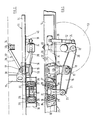
- the suspension shown in the drawings is intended to support the chassis 11 of a vehicle from an axle 12, which in turn is supported on road wheels 13.
- the suspension also has to allow vertical movement of the chassis 11 against spring loading and allow the chassis 11 to roll.
- the chassis 11 is carried on the axle 12, it is conventional to refer location of and support for the axle 12 with respect to the chassis 11 and that convention will be followed in the specification.
- the suspension is identical, although of opposite hand, on both sides of the chassis 11 and consequently only one side of the suspension is illustrated in the drawings and will be described in the following description.
- the chassis 11 comprises a pair of longitudinal members 14 which are interconnected at spaced locations by a plurality of cross members 15.
- the axle 12 is disposed transversely of the chassis 11, the ends extending beyond the longitudinal members 14 of the chassis 11 and being provided with hub assemblies to which the road wheels 13 may be attached.
- a main suspension beam 16 is provided on each side of the chassis 11.
- Each beam 16 is a welded steel fabrication of generally I-section.
- a phospher-bronze bush 17 is provided in the central portion of the beam 16, by which it is pivotally connected about a pivot pin 18 to a chassis bracket 19 extending downwardly from the chassis 11 on the outside of longitudinal member 14.
- the ends 20 and 21 of the beam 16 are cranked away from the vertical projection of the longitudinal member 14 and are provided with spherical rubber bushes 22 and 23.
- the trailing end 20 of the beam 16 is connected via bush 22 to a bracket 24 extending down from the axle 12 adjacent the end thereof.
- An elastomeric spring 25 includes a pair of spring units 26 and 27 each made up of a plurality of layers 28 of elastomeric material interposed with rigid plates 29 to which the layers 28 are bonded.
- Spring units 26 and 27 are mounted longitudinally of one another against the outer side of longitudinal member 14, in a frame 30.
- the spring units 26 and 27 form an "inclined shear pair" being mounted in the frame 30 so that they are mutually inclined, the plates 29 of one spring 26 diverging upwardly with respect to plates 29 of the other spring 27.
- a wedge assembly 31 is mounted between the diverging upper faces of spring units 26 and 27, the wedge member 21 extending downwardly between the spring units 26 and 27 and being connected to end 21 of beam 16 by means of bush 23.
- the spring 25 will oppose vertical loads applied to the beam 16 through axle 12.
- the spring units 26 and 27 are such that the layers 28 of elastomeric material are loaded partially in compression and partially in shear between adjacent plates 29.
- the spring units 26 and 27 may be positioned transversely of one another, so as to provide additional compliant lateral location of the beam 16.
- a V-shaped torque member 32 (only one arm shown) is connected via a spherical rubber bush 33 at its apex to a bracket 34 extending upwardly from the middle of the axle 12, in this case the differential housing 35.
- the end of the arms 36 of the torque assembly 32 are connected via spherical bushes 37 to brackets 38 mounted on the inside of longitudinal chassis members 14.
- the torque assembly 32 being spaced above the beams 16 provides location of the axle against rotation about its own axis and also provides additional longitudinal and lateral location of the axle.
- a telescopic shock absorber 39 is connected between the axle bracket 24 and a bracket 40 mounted on the outside of longitudinal member 14.
- the major components are positioned outside the longitudinal members 14 where there are fewer restrictions on space and the components are easily accessible from the side of the vehicle.
- the spring 25 is mounted within the depth of the chassis 11 and consequently the spacing between the chassis and axle may be reduced within the limits of the axle movement required. Also, there is very little need for parts of the suspension or chassis to extend significantly beyond the axle. These can be particularly attractive features for tipper vehicles and other specialist vehicles requiring wheels near the back of the chassis.
- the relatively open rearward region of the axle also provides a convenient location for other components, for example, brake actuators.
- the suspension described above is also particularly suitable for narrow chassis vehicles.
- Conventional leaf spring suspensions are not suitable for such vehicles because attachment of the spring to the axle will be well inboard which will result in poor roll stability.
- the ends of the beams 16 may be offset sufficiently to allow them to be connected to the axle adjacent its ends, thereby improving the roll stability.
- elastomeric springs of the form described above other forms of elastomeric spring, for example elastomeric springs of toroidal configuration, or even conventional helical compression springs or leaf springs may be used.
- damping means are included between the axle and chassis, these may be connected between the axle bracket and chassis as illustrated in the drawings or between the chassis and beam 16 on either side of the pivot 18.
- the damping means could be arranged to act directly on the wedge assembly 31.
- the phosphor-bronze bush 17 may be replaced by a solid bush made from any other suitable bearing material or may be replaced by for example, a roller or ball bearing.
- the rubber bush 22 between the axle bracket 24 and beam 16 will attentuate the transmission of vibrations from the axle 12 to the beam 16 and thence to the chassis 11.
- an elastomeric bush comprising a cylindrical sleeve of rubber sandwiched between concentric steel sleeves may replace bush 17 and will serve to isolate vibrations in the beam 16 from the chassis 11 while also allowing some lateral compliance of the axle 12.
Landscapes
- Engineering & Computer Science (AREA)
- Mechanical Engineering (AREA)
- Vehicle Body Suspensions (AREA)
Applications Claiming Priority (2)
| Application Number | Priority Date | Filing Date | Title |
|---|---|---|---|
| GB868602821A GB8602821D0 (en) | 1986-02-05 | 1986-02-05 | Vehicle suspensions |
| GB8602821 | 1986-02-05 |
Publications (2)
| Publication Number | Publication Date |
|---|---|
| EP0235960A2 true EP0235960A2 (de) | 1987-09-09 |
| EP0235960A3 EP0235960A3 (de) | 1987-11-19 |
Family
ID=10592549
Family Applications (1)
| Application Number | Title | Priority Date | Filing Date |
|---|---|---|---|
| EP87300971A Withdrawn EP0235960A3 (de) | 1986-02-05 | 1987-02-04 | Fahrzeugaufhängungen |
Country Status (2)
| Country | Link |
|---|---|
| EP (1) | EP0235960A3 (de) |
| GB (1) | GB8602821D0 (de) |
Cited By (2)
| Publication number | Priority date | Publication date | Assignee | Title |
|---|---|---|---|---|
| EP0531688A3 (de) * | 1991-08-07 | 1994-02-16 | Deere & Co | |
| EP0739764A1 (de) * | 1995-04-26 | 1996-10-30 | Paccar Inc. | V-Form-Gestängeanordnung für eine Aufhängung |
Family Cites Families (7)
| Publication number | Priority date | Publication date | Assignee | Title |
|---|---|---|---|---|
| DE1031654B (de) * | 1954-03-11 | 1958-06-04 | Georg Bracke Dr Ing | Radabfederung, insbesondere fuer Fahrzeuge |
| GB940085A (en) * | 1961-03-16 | 1963-10-23 | Metalastik Ltd | Improvements in or relating to equalised bogies for railway vehicles |
| FR1267549A (fr) * | 1960-09-09 | 1961-07-21 | Vehiculos Automoviles Sa | Perfectionnements aux trains avant de véhicules automobiles |
| FR1536401A (fr) * | 1967-07-05 | 1968-08-16 | Pneumatiques, Caoutchouc Manufacture Et Plastiques Kleber Colombes | Ressort en caoutchouc pour suspension de véhicule ou application similaire |
| GB1498403A (en) * | 1973-12-20 | 1978-01-18 | Wragg R | Vehicle suspensions |
| FR2398627A1 (fr) * | 1977-07-28 | 1979-02-23 | Ftf | Dispositif de suspension avec amortisseur incorpore pour un vehicule |
| FR2483857A1 (fr) * | 1980-06-06 | 1981-12-11 | Ftf | Dispositif de suspension a amortisseurs incorpores et a roues independantes, notamment pour les remorques |
-
1986
- 1986-02-05 GB GB868602821A patent/GB8602821D0/en active Pending
-
1987
- 1987-02-04 EP EP87300971A patent/EP0235960A3/de not_active Withdrawn
Cited By (2)
| Publication number | Priority date | Publication date | Assignee | Title |
|---|---|---|---|---|
| EP0531688A3 (de) * | 1991-08-07 | 1994-02-16 | Deere & Co | |
| EP0739764A1 (de) * | 1995-04-26 | 1996-10-30 | Paccar Inc. | V-Form-Gestängeanordnung für eine Aufhängung |
Also Published As
| Publication number | Publication date |
|---|---|
| GB8602821D0 (en) | 1986-03-12 |
| EP0235960A3 (de) | 1987-11-19 |
Similar Documents
| Publication | Publication Date | Title |
|---|---|---|
| CA2056608C (en) | Tandem wheel and axle suspension | |
| US4848789A (en) | Vehicle chassis tranverse structural member | |
| US6588779B2 (en) | Vehicle wheel suspension arrangement | |
| US3792871A (en) | Linkage component for vehicle suspension | |
| US4422666A (en) | Suspension mechanism for automotive vehicles | |
| SU1618279A3 (ru) | Подвеска дл колес автомобил | |
| US6390485B1 (en) | Vehicle suspension | |
| EP1615788B1 (de) | Radaufhängung für fahrzeuge | |
| EP0914978B1 (de) | Aufhängung für fahrzeuge mit zwei hinterachsen | |
| MXPA06003550A (es) | Suspension de eje de direccion. | |
| US4946189A (en) | Rear suspension | |
| US5873586A (en) | Rocking beam suspension | |
| US2145670A (en) | Swinging half-axle suspension | |
| US4087115A (en) | Motor vehicle rear wheel suspension | |
| WO1995023725A1 (en) | Arrangement for suspension of a sprung vehicle cab on a vehicle frame | |
| EP0015015B1 (de) | Radaufhängung für Fahrzeuge | |
| US4583614A (en) | Mounting power unit in front wheel vehicle | |
| EP1467905B1 (de) | Buchsenanordnung für stabilisator | |
| EP0045411A2 (de) | Ausgeglichene Vier-Feder-Aufhängevorrichtung für Doppelachsaggregat | |
| US4355696A (en) | Axle suspension for the driven axle of a road vehicle | |
| US4519628A (en) | Vehicle suspensions | |
| GB2222987A (en) | Vehicle wheel suspension system | |
| JP3656365B2 (ja) | アクスルケースと車体フレームとの連結構造 | |
| EP3738801A1 (de) | Hinterradaufhängungssystem für ein fahrzeug | |
| EP1910108B1 (de) | Einzelradaufhängung |
Legal Events
| Date | Code | Title | Description |
|---|---|---|---|
| PUAI | Public reference made under article 153(3) epc to a published international application that has entered the european phase |
Free format text: ORIGINAL CODE: 0009012 |
|
| AK | Designated contracting states |
Kind code of ref document: A2 Designated state(s): BE DE ES FR GB IT SE |
|
| PUAL | Search report despatched |
Free format text: ORIGINAL CODE: 0009013 |
|
| RHK1 | Main classification (correction) |
Ipc: B60G 3/14 |
|
| AK | Designated contracting states |
Kind code of ref document: A3 Designated state(s): BE DE ES FR GB IT SE |
|
| STAA | Information on the status of an ep patent application or granted ep patent |
Free format text: STATUS: THE APPLICATION IS DEEMED TO BE WITHDRAWN |
|
| 18D | Application deemed to be withdrawn |
Effective date: 19880520 |
|
| RIN1 | Information on inventor provided before grant (corrected) |
Inventor name: SAUNDERS, THOMAS GOODWIN |