EP0236108B1 - Traitement de signal de tachymètre - Google Patents
Traitement de signal de tachymètre Download PDFInfo
- Publication number
- EP0236108B1 EP0236108B1 EP87301792A EP87301792A EP0236108B1 EP 0236108 B1 EP0236108 B1 EP 0236108B1 EP 87301792 A EP87301792 A EP 87301792A EP 87301792 A EP87301792 A EP 87301792A EP 0236108 B1 EP0236108 B1 EP 0236108B1
- Authority
- EP
- European Patent Office
- Prior art keywords
- signal
- input
- output signal
- output
- period
- Prior art date
- Legal status (The legal status is an assumption and is not a legal conclusion. Google has not performed a legal analysis and makes no representation as to the accuracy of the status listed.)
- Expired - Lifetime
Links
Images




Classifications
-
- G—PHYSICS
- G06—COMPUTING OR CALCULATING; COUNTING
- G06F—ELECTRIC DIGITAL DATA PROCESSING
- G06F7/00—Methods or arrangements for processing data by operating upon the order or content of the data handled
- G06F7/60—Methods or arrangements for performing computations using a digital non-denominational number representation, i.e. number representation without radix; Computing devices using combinations of denominational and non-denominational quantity representations, e.g. using difunction pulse trains, STEELE computers, phase computers
- G06F7/68—Methods or arrangements for performing computations using a digital non-denominational number representation, i.e. number representation without radix; Computing devices using combinations of denominational and non-denominational quantity representations, e.g. using difunction pulse trains, STEELE computers, phase computers using pulse rate multipliers or dividers pulse rate multipliers or dividers per se
Definitions
- This invention relates generally to an apparatus for producing a periodic output signal having a predetermined frequency and phase relationship to a periodic input signal, and more particularly relates to a tacho signal processing apparatus for producing a plurality of output signals each having a predetermined frequency and phase relationship to a single tachometer input signal.
- the invention has particular application to condition monitoring of gearboxes and other complex rotating machinery.
- gearboxes In order to monitor the behaviour of gearboxes and similar geared mechanical rotating machinery, and in particular to be able to detect damage therein, it has been proposed that signals representative of vibrations produced from the gearbox be examined to provide information relating to the gearbox components.
- gearboxes typically have a number of rotating components, each rotating with a different period defined according to the gear ratios.
- the vibrations to be analysed are likely to arise from all components and, hence, it is not possible to identify a particular component of a vibration signal with a particular rotating component unless a signal representative of the rotational period of that component can be provided.
- a gear having a missing or damaged tooth may repetitively produce an identifiable vibration feature at a specific position of the gear component as it turns, and in order to identify this vibration feature with the responsible gear component it is necessary to have available a signal representative of the period and phase of rotation of the respective component.
- phase locked loop circuits are considered to represent the closest prior art from which the present invention starts.
- prior art circuits suffer from the disadvantage of limited operating frequency range, and inadequate response to changes in rotational frequencies. If the shaft speeds change too rapidly, loss of lock is likely to occur resulting in inability to identify a vibration-inducing feature as a function of shaft angle.
- GB-A-2052815 describes a digital frequency multiplier in which the period of a signal is measured against a divided down clock signal and the resultant number is supplied to a comparator where it is compared with the count from a clock counter. Coincidence of the two counts will occur N times during the incoming signal period so that the comparator output will be at N x the incoming frequency.
- This apparatus should be capable of responding to relatively rapid changes in shaft speed over a wide range of speeds. Additionally, it is preferable for such an apparatus to conveniently add onto vibration analysis equipment, or be incorporated within it.
- an apparatus for producing a periodic output signal having a predetermined frequency and phase relationship to a variable frequency periodic input signal comprising: input means for evaluating the successive periods of said periodic input signal as multiples of a clock signal period (T c ) and outputting a succession of first data signals (k i ) each representative of the duration of a corresponding period of the periodic input signal; control means coupled to said input means for receiving said first data signals (k i ) therefrom, said control means being adapted to operate upon each said first data signals so as to derive a succession of second data signals (n i ) each representative of a quantity (n i ) having a relationship to a respective one of said first data signals (k i ), the quantity (n i ) including a first component determined from said first data signal (k i ) and from said predetermined frequency relationship and a second component (dk i ) determined by calculating the difference between said corresponding first data signal (k i ) and the
- the apparatus can be connected to receive a periodic input signal from a tachometer attached to one shaft of a gear train and, by providing to the control means a definition of the predetermined gear ratio of a specific gear component within the gear train, an output signal representative of the period and phase of rotation of that specific component can be simply produced.
- the apparatus can be easily transferred to different gearboxes, since it requires connection only to a tachometer on an input or output shaft of the gearbox and definition of the gearing ratio for the shaft which it is desired to examine in order for a corresponding output signal relevant to that shaft to be produced.
- a plurality of said output signal generation means may be provided, and said control means may be arranged to receive a plurality of said first inputs and said second input and to calculate a respective data signal for each output signal generation means.
- said control means may be arranged to receive a plurality of said first inputs and said second input and to calculate a respective data signal for each output signal generation means.
- a gearbox having a plurality of shafts with different gearing ratios can have a tachometer attached to a single shaft of the gearbox, and by providing to the control means a definition of the gear ratio for each shaft relative to the shaft producing the tachometer input signal, outputs for each rotating shaft in the gearbox can be produced.
- the invention can also be embodied in an installation comprising a plurality of remote slave units each including a respective said input means and a respective said output means and with all the slave units being connected to a master control means adapted to calculate respective data signals for each slave unit on the basis of (i) allocated definitions of respective period ratios and (ii) the evaluation signals derived by the input means of the respective slave units from respective periodic input signals provided thereto.
- a master control means adapted to calculate respective data signals for each slave unit on the basis of (i) allocated definitions of respective period ratios and (ii) the evaluation signals derived by the input means of the respective slave units from respective periodic input signals provided thereto.
- An apparatus will preferably include means for monitoring the period length of the input signal and causing the apparatus to ignore a pulse which clearly does not belong to the periodic input signal on account for example of the pulse occurring sooner than a pre-selected portion of said monitored period length. Consequently, if for some reason a spurious pulse occurs out of time with the periodic input signal, the spurious pulse will not produce an incorrect output signal, so that the synchronism between the true input signal and the output signal will be maintained. Such spurious pulses can frequently occur in practice in the presence of interfering electromagnetic radiation or other signals.
- an apparatus may incorporate means for missing input pulse detection, such means operating for example by monitoring the period length of the input signal and, in response to absence of the next expected input signal, effecting a compensation for the absent signal.
- the input means comprises a counter timer receiving clock pulses at a frequency of 1MHz for example and adapted for each period of an input tacho signal to provide to the control means an evaluation signal corresponding to a count of the number of clock pulses received during the respective tacho period.
- the control unit comprises a microprocessor to which data is provided representative of the known predetermined period ratio between the input and output signals, such ratio corresponding in a gearbox application for example to the gear ratio that exists between the shaft of the gearbox with which the tachometer is associated and the other shaft under investigation, and as will be described in more detail hereinafter the microprocessor has the task of calculating a data signal to be written into the output signal generation means, such data signal being derived from the evaluation signal received from the counter timer input means in accordance with the predetermined gear ratio data.
- the output signal generation means comprises an accumulator connected to receive the clock pulses that are counted in the counter timer input means and arranged to have added into it at regular periodic intervals the data signal derived from the microprocessor control unit. When the accumulated value in the accumulator reaches a predetermined point, which in the embodiment in question is the point at which the accumulator fills to capacity, an output pulse signal is generated and the successive generation of such output signals defines the required periodic output signal.
- the output signal generation means makes use of an adding circuit having a first input from a first register coupled to the output of the microprocessor and a second input from a second register constituting the aforementioned accumulator, the adding circuit having its output coupled to the accumulator. At regular periodic intervals the adding circuit is actuated and its output value is placed in the accumulator, that is to say the second register. When a carry out of the most significant bit of the adding circuit occurs, the output signal is actuated.
- the invention also extends to an apparatus for analysing vibrations in a machine having a plurality of interconnected parts rotating at different speeds, said apparatus comprising: a vibration transducer mounted on said machine and adapted to output a vibration signal representative of the machine vibrations, said vibration signal including components having derivations in the different rotating parts of the machine; a tachometer coupled to one of the rotating parts of the machine for delivering a periodic output signal indicative of the rotation thereof; a counter timer connected to receive said tachometer output signal at a first input thereof and to receive a constant frequency clock signal at a second input thereof, said counter timer being adapted to output a count value (k i ) representative of the number of clock signals received in each period of the tachometer output signal; a control unit coupled to said counter timer to receive therefrom said count value (k i ) for each period of the tachometer output signal, said control unit being adapted to compute a value (n i ) having a first component determined from said count value (k i )
- the apparatus shown therein comprises a clock 10 providing pulses at a frequency fc of approximately 1MHz (a period of 1 microsecond) to a counter timer 11 and to an output signal generation unit indicated generally at 12.
- the output signal generation unit can be considered as a digital oscillator.
- the counter timer 11 receives clock pulses at an input 13 and signals from a tachometer (not shown) at an input 14.
- the tachometer is attached to one shaft of a gear train under investigation and the apparatus illustrated is adapted to generate a periodic output signal having a periodicity and phase relationship to the input signal which corresponds to the rotation of a second specified shaft in the gear train.
- the counter timer measures the number of clock pulses received in each time period 101, 102, 103 etc.
- the counter timer 11 is provided with memory means so that on receipt of a tacho pulse defining the end of a tacho period, it saves the measured number of clock pulses, resets to zero and commences counting the number of clock pulses for the next period.
- the flow diagram illustrating this action is shown in Figure 2.
- the output from the counter timer 11 is passed via a bus 15 to the control unit 20.
- An interrupt line 16 links the timer counter 11 to the unit 20 to indicate to the unit 20 that a value on bus 15 is to be read.
- the control unit 20 comprises a microprocessor having a fast interrupt response for the input line 16 and a 32 arithmetic bit capability which can accept inputs on bus 15.
- the unit 20 is interconnected via a bus or other interface 21 to a host computer system or other device which provides data to the microprocessor which is representative of the predetermined period ratio between the input signal to counter timer 11 and the required output signal, that is to say, the gear ratio of the shaft being investigated.
- the control unit calculates a value n to be written in the register 30 in response to new input values k announced by an interrupt on line 16.
- the finite time necessary to calculate the new value of n for each tacho period appears as a delay in the system.
- the delay should be the same for each tacho period, no matter what the actual processing time of the calculation may be. This may be achieved by delaying the update of the register 30 for a fixed period, greater than the maximum interrupt latency plus processing time, after the counter timer has made a new period measurement.
- a buffer register may be employed to ensure this and also to ensure that no partially modified register value is added to the accumulator.
- the output signal generation means 12 comprises a 32 bit register 30, a 32 bit adder 31, and a 32 bit register accumulator 17.
- the accumulator 17 receives the clock pulses from clock 10 at a clock input 33 and has a first output bus 35 looped back to adder 31.
- the periodic output signal is provided on a second output line 34.
- the value n in the register 30 is added via adder 31 to the contents of the accumulator 17 on bus 35 and the sum is entered into the accumulator.
- the output on line 34 is taken from the most significant bit of the accumulator 17.
- the accumulator has a maximum count of 232-1 so that an accumulation of 232 counts corresponds to one period (360°) of the output signal on line 34.
- the value added into the accumulator 17 at each clock pulse determines the rate at which the accumulator fills and thus determines the period of the output on line 34.
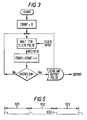
- tacho input signals are received by the counter timer unit 11 and at the end of each tacho signal period, the control unit 20 calculates a count value n to be added into register 30, the count value being calculated, for example, according to the flow diagram shown in Figure 4.
- Figure 3 illustrates how the current count value stored in register 30 is added to the accumulator 17 on receipt of each clock pulse. When the accumulator 17 overflows, an output signal is produced on the output 34.
- the theory behind the calculation of the count value n and the flow diagram shown in Figure 4 is explained below.
- the frequency of the signal output on line 34 is required to be a/b times the tacho input signal frequency, where a/b is the gear ratio of the shaft under investigation.
- n is determined, which must correct this error during the succeeding tacho period 103 on the assumed basis that the succeeding tacho period 103 will be the same length as the current tacho period 102.
- the error accumulated during the i th tacho period should most conveniently be corrected by adjusting the value of n for the (i + 1) th tacho period so that by the end of the (i + i) th period the error has been reduced to zero.
- n i 232a k i b + dk i n i-1 k i
- next (i + 1) th tacho period 103 proves to be exactly k i clock pulses long, the error will have been exactly compensated for by the end of the period. If not, there will be another (different) error (k i - k i-1 )n i at the end of the (i + 1) th cycle, and this must be compensated for during the succeeding (i + 2) th tacho period in the same way.
- n and k are integers.
- equation H assuming that 232 a/b is an integer, the division by k i can give rise to a non-integral result and this must be truncated to give an integral value of n i . This introduces an additional source of error which it is possible to compensate for at the end of each tacho period.
- the division by k i will in general leave a remainder r i , which represents that portion of the phase error which occurred during the i th tacho cycle which will remain uncorrected during the following (i + 1) th tacho cycle.
- the remainder r i can thus be added into the error correction term for the following (i + 1) th tacho period.
- an output signal can be generated at a frequency which is adjusted so as to minimise the phase error produced by changes in input frequency. In the steady state the phase error is reduced to zero.
- the finite time necessary to calculate the new value of n for each tacho period appears as a delay in the system.
- the delay should be the same for each tacho period, no matter what the actual processing time of the calculation may be.
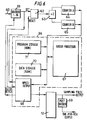
- FIG. 6 illustrates a block diagram of a system embodying the present invention.
- the input tacho signal appears on line 60 which is fed into a variable modulus pre-scaler 61 to allow a greater range of input signal frequencies to be handled by the apparatus.
- the signals therefrom pass to a set/reset latch 62 which permits the pulse to be transmitted to the next stage only following a selectable fraction of the input period. This implements the spurious pulse rejection described above.
- the processor 66 controls the fraction of the input period during which pulses will be ignored by resetting the latch.
- the signal from the latch 62 is used to toggle a divide by 2 flip-flop 63 providing inputs to two counters 64 and 65 with a common input clock.
- the values in these two counters can then be read by a microprocessor 67 of the control unit 66.
- Two counters are employed so that one is timing the interpulse duration whilst the other is available to be read by the microprocessor and reset to zero.
- the algorithm I above is implemented by the microprocessor.
- Improvements may be added to the processor algorithm to deal with glitch rejection.
- the principle is to limit the effect of spurious input pulses by making the assumption that the rate of change of the input signal frequency is limited.
- the maximum rate of change can be specified by the user, typically being set at 5% change per input cycle.
- the input latch 62 is only reset to receive a pulse after 95% of the time period of the previous pulse has elapsed. Should a pulse occur before this, it is treated as a glitch and ignored. Nonetheless, in order that step changes in the input signal frequency produced, for example, by switching from one shaft tacho to another can be accommodated, a glitch occurring twice causes latch 62 to be reset immediately after detection of a subsequent tacho pulse. Missing pulse detection may also be performed by checking the tacho input period to see if it corresponds to roughly twice the previous tacho input period. If it does, the count value k for the respective period is halved and processing continues.
- Tacho period measurement is provided by the counters with 1 microsecond resolution and a maximum count of 16 million, thus theoretically input frequencies down to 0.06 Hz can be handled.
- the minimum input frequency is set as 0.25 Hz.
- the upper frequency limit is primarily determined by the execution speed of the algorithm since the new count value n must be calculated before the next input transition. Since the execution time is not constant, the external hardware performs the output updating at a suitable time after the output frequency value n has been placed in the buffer. By choosing this to be 250»S it allows a theoretical maximum input frequency of 4 kHz: this provides a comfortable margin if further software modifications are required.
- At least 23 bit control over the output frequency is provided which gives increments of frequency so that sufficiently fine control is available when higher frequencies are being generated.
- the output signal generation unit 12 may provide the sampling output and if a once-per-rev output is desired at the output frequency, this can be provided via a programmable divider 69.
- the heart of the control unit 66 is a Motorola 68000 microprocessor, which runs at a clock speed of 10 MHz. It is provided with 16 Kbytes of RAM 70, and 16 Kbytes of ROM 71, in addition to two 68230 chips, which provide counters 64 and 65.
- the output signal generator 12 is implemented using eight SN74LS681 accumulator/adder register chips.
- FIG. 7 illustrates an arrangement embodying the present invention wherein respective tacho input signals are presented to a plurality of slave units 80 together with, in each case, a vibration signal which is to be analysed.
- the slave unit operates in the manner described above to implement both the input counter/timer means and the output signal generation means.
- each slave unit makes available to the master processor 81 the time interval measured for the previous tacho input signal period.
- the master processor calculates the required count increment value n for each slave unit according to a stored algorithm.
- the respective n values are then fed back to the slave units which use them directly to control the rate of sampling of the respective vibration signal input for its onboard analogue-to-digital converter.
- the communication between slave and master takes place over a bus 82 which allows the number of slave units to be expanded to the required number of channels.
- the number of slave units that can be controlled by one master depends on the master processor's calculation speed and also the rate of tacho pulse input. In one example, 16 slaves can be accommodated at tacho frequencies up to 1000 Hz.
- a single master processor accessing multiple values of a/b can evaluate a number of parallel outputs from the same tacho input.
- a single control unit can provide multiple signal analyses based on a single tacho input signal.
- the response of the output signal lags at the most just over one tachometer period behind the true shaft behaviour, which is the best that can be achieved by any sampled data system and is considerably better than any current analogue or digital phase locked loop frequency multiplier system.
Landscapes
- Engineering & Computer Science (AREA)
- General Physics & Mathematics (AREA)
- Theoretical Computer Science (AREA)
- Physics & Mathematics (AREA)
- Mathematical Analysis (AREA)
- Mathematical Optimization (AREA)
- Mathematical Physics (AREA)
- Pure & Applied Mathematics (AREA)
- General Engineering & Computer Science (AREA)
- Computational Mathematics (AREA)
- Computing Systems (AREA)
- Measurement Of Mechanical Vibrations Or Ultrasonic Waves (AREA)
- Control Of Electric Motors In General (AREA)
- Control Of Motors That Do Not Use Commutators (AREA)
- Measurement Of Velocity Or Position Using Acoustic Or Ultrasonic Waves (AREA)
- Electrophonic Musical Instruments (AREA)
- Power Steering Mechanism (AREA)
- Transmission And Conversion Of Sensor Element Output (AREA)
- Holo Graphy (AREA)
- Liquid Developers In Electrophotography (AREA)
Claims (18)
- Appareil pour produire un signal de sortie périodique présentant une relation de fréquence et de phase prédéterminée par rapport à un signal d'entrée périodique de fréquence variable, ledit appareil comportant:
un moyen d'entrée (11) pour évaluer les périodes successives dudit signal d'entrée périodique en tant que multiples d'une période de signal d'horloge (Tc) et pour délivrer une succession de premiers signaux de données (ki) représentatifs chacun de la durée d'une période correspondante du signal d'entrée périodique;
un moyen de commande (20) couplé audit moyen d'entrée pour en recevoir lesdits premiers signaux de données (ki), ledit moyen de commande étant apte à traiter chacun desdits premiers signaux de données de manière à obtenir une succession de seconds signaux de données (ni) représentatifs chacun d'une quantité (ni) ayant une relation avec un signal respectif parmi lesdits premiers signaux de données (ki), la quantité (ni) comprenant une première composante proportionnelle au premier signal de données correspondant (ki) et une seconde composante (dki) déterminée en calculant la différence entre ledit premier signal de données correspondant (ki) et le premier signal de données (ki-1) précédant immédiatement ledit premier signal de données correspondant (ki), la seconde composante (dki) représentant ainsi le changement de périodicité dudit signal d'entrée et étant ajoutée à ladite première composante afin de permettre d'effectuer une correction de la phase du signal de sortie pour tenir compte du retard fini inhérent au fonctionnement dudit moyen de commande pour obtenir lesdits seconds signaux de données (ni); et
un moyen de génération de signal de sortie (12) couplé audit moyen de commande (10) pour en recevoir lesdits seconds signaux de données (ni), et comprenant des moyens formant accumulateur (17) qui sont incrémentés, à une cadence égale à une fréquence d'horloge, de la valeur des seconds signaux de données reçus, ledit moyen de génération de signal de sortie (12) produisant un signal de sortie (34) chaque fois que la valeur cumulée atteint des niveaux prédéterminés. - Appareil selon la revendication 1, dans lequel ledit moyen de génération de signal de sortie (12) comporte un premier registre (30) ayant une entrée couplée auxdits moyens de commande (20) pour en recevoir lesdits seconds signaux de données (ni), un à la fois, et une sortie, un second registre constituant lesdits moyens formant accumulateur (17) et ayant une entrée et une sortie, et un circuit d'addition (31) ayant une première entrée reliée à la sortie dudit premier registre et une seconde entrée reliée à la sortie (35) dudit second registre (17) et ayant une sortie reliée à l'entrée dudit second registre, le circuit d'addition (31) étant agencé de façon à incrémenter de manière répétée le second registre de la valeur introduite dans le premier registre à ladite fréquence d'horloge, et le moyen de génération de signaux de sortie étant agencé pour fournir ledit signal de sortie chaque fois que la capacité du second registre est atteinte.
- Appareil selon la revendication 1 ou 2, comprenant une multiplicité desdits moyens de génération de signaux de sortie associés de manière fonctionnelle à un dit moyen de commande unique, ledit moyen de commande étant apte à obtenir pour chacun desdits moyens de génération de signaux de sortie lesdits seconds signaux de données respectifs.
- Appareil selon l'une quelconque des revendications précédentes, dans lequel ledit moyen d'entrée est apte à évaluer les périodes successives dudit signal d'entrée périodique en tant que multiples entiers de ladite période de signal d'horloge et ledit moyen de commande est apte à obtenir lesdits seconds signaux de données représentatifs de quantités formant nombres entiers, et dans lequel la quantité (ni) obtenue par ledit moyen de commande (20) comprend une troisième composante (ri) représentant une valeur de reste résultant de la troncature de la seconde composante de la quantité (ni-1) immédiatement précédente de manière à produire une quantité formant nombre entier, troisième composante qui est ajoutée auxdites première et seconde composantes pour permettre d'effectuer une correction de la phase du signal de sortie afin de tenir compte de ladite troncature.
- Appareil selon la revendication 4, dans lequel ladite unité de commande (20) est apte à évaluer l'expression:
 C = ledit niveau prédéterminé qui s'est accumulé dans ledit accumulateura/b = ladite relation de fréquence prédéterminéeki = le multiple de la période du signal d'horloge délivrée par le moyen d'entrée pour la ième période du signal d'entrée périodique;dki = ki-1 - ki;ni-1 = la partie formant nombre entier de l'évaluation de ladite expression pour la (i-1)ème période du signal d'entrée périodique; etri-1 = le reste subsistant après la partie formant nombre entier de l'évaluation de ladite expression pour la (i-1)ème période du signal d'entrée périodique.
 - Appareil selon l'une quelconque des revendications précédentes, dans lequel ledit signal d'entrée périodique comporte un signal tachymétrique représentatif de la rotation d'un premier corps rotatif et ladite relation de fréquence prédéterminée correspond à la relation entre ledit premier corps rotatif et un second corps rotatif qui lui est couplé suivant un rapport de démultiplication prédéterminé (a/b), et dans lequel ledit appareil comporte en outre des moyens pour élaborer un signal représentatif des vibrations desdits corps rotatifs, ainsi que des moyens pour analyser ledit signal de vibrations à la fréquence dudit signal de sortie périodique pour déterminer la condition dudit second corps rotatif.
- Appareil selon la revendication 1, dans lequel:
ledit moyen d'entrée (11) comporte une première entrée (14) pour recevoir ledit signal d'entrée périodique, une seconde entrée (13) pour recevoir un signal d'horloge de fréquence constante, et une sortie (15), et dans lequel lesdits premiers signaux de données délivrés comportent un signal de comptage (ki) représentatif du nombre entier de signaux d'horloge apparaissant au cours de la ième période du signal d'entrée;
ledit moyen de commande (20) comporte une première entrée reliée à la sortie (15) desdits moyens d'entrée (11) pour en recevoir ledit signal de comptage (ki), une seconde entrée pour recevoir un signal de commande (a/b) représentatif de ladite relation de fréquence prédéterminée, et une sortie; et
ledit moyen de génération de signaux de sortie (12) comporte une première entrée reliée audit moyen de commande (20) pour en recevoir ledit signal représentatif de la quantité formant nombre entier (ni), une seconde entrée (33) pour recevoir ledit signal d'horloge de fréquence constante, et une sortie (34), ledit moyen de génération de signaux de sortie étant apte à incrémenter de façon répétée de ladite quantité formant nombre entier (ni) une valeur de comptage cumulée à la fréquence dudit signal d'horloge reçu à sa dite seconde entrée et à fournir un signal au niveau de ladite sortie chaque fois que la valeur de comptage cumulée atteint des niveaux uniformément espacés prédéterminés. - Appareil selon la revendication 7, dans lequel ledit moyen de génération de signaux de sortie (12) comprend un accumulateur (17) ayant une capacité de comptage maximale de (C-1), et il est prévu qu'une sortie soit fournie à partir dudit moyen de génération de signaux chaque fois que la capacité de l'accumulateur est atteinte.
- Appareil selon la revendication 8, dans lequel ledit moyen de génération de signaux de sortie (12) comporte un premier registre (30) couplé audit moyen de commande (20) pour en recevoir lesdits signaux représentatifs de ladite quantité formant nombre entier (ni), un second registre constituant ledit accumulateur (17), et des moyens d'addition (31) couplés auxdits premier et second registres pour incrémenter de façon répétée de la quantité contenue par le premier registre la valeur de comptage contenue par le second registre à la fréquence dudit signal d'horloge.
- Appareil selon l'une quelconque des revendications 7 à 9, comportant en outre une multiplicité desdits moyens de génération de signaux de sortie reliés de manière fonctionnelle à un dit moyen de commande unique, ledit moyen de commande étant apte à obtenir, pour chacun desdits moyens de génération de signaux de sortie, des signaux de quantité formant nombre entier (ni) respectifs obtenus en fonction de signaux de commande (a/b) respectifs.
- Appareil selon l'une quelconque des revendications 7 à 9, dans lequel ledit signal d'entrée périodique comporte un signal tachymétrique représentatif de la rotation d'un premier corps rotatif et ladite relation de fréquence prédéterminée correspond à la relation entre ledit premier corps rotatif et un second corps rotatif qui lui est couplé suivant un rapport de démultiplication prédéterminé, et dans lequel ledit appareil comporte en outre des moyens pour élaborer un signal représentatif des vibrations desdits corps rotatifs et des moyens pour analyser ledit signal de vibrations à la fréquence dudit signal de sortie périodique pour déterminer la condition dudit second corps rotatif.
- Appareil selon la revendication 10, dans lequel ledit signal d'entrée périodique comporte un signal tachymétrique représentatif de la rotation d'un premier corps rotatif et ladite relation de fréquence prédéterminée pour chaque moyen parmi ladite multiplicité de moyens de génération de signaux de sortie correspond à la relation entre ledit premier corps rotatif et un corps respectif parmi une multiplicité de seconds corps rotatifs, et dans lequel ledit appareil comporte en outre des moyens pour élaborer des signaux représentatifs des vibrations desdits corps rotatifs et des moyens pour analyser lesdits signaux de vibrations aux fréquences respectives des signaux de sortie périodiques de ladite multiplicité de moyens de génération de signaux de sortie.
- Appareil selon la revendication 11 ou 12, dans lequel lesdits premier et second corps rotatifs sont constitués par des composants se trouvant dans une boîte de vitesses.
- Appareil pour analyser des vibrations se produisant dans une machine comportant une multiplicité de pièces interconnectées qui tournent à différentes vitesses, ledit appareil comportant:
un transducteur de vibrations monté sur ladite machine et apte à délivrer un signal de vibrations représentatif des vibrations de la machine, ledit signal de vibrations comprenant des composantes ayant des dérivations dans les différentes pièces rotatives de la machine;
un tachymètre couplé à l'une des pièces rotatives de la machine pour délivrer un signal de sortie périodique représentatif de sa rotation;
un compteur-intervallomètre (11) relié pour recevoir ledit signal de sortie du tachymètre à une première entrée de celui-ci et pour recevoir un signal d'horloge de fréquence constante à une seconde entrée de celui-ci, ledit compteur-intervallomère étant apte à délivrer une valeur de comptage (ki) représentative du nombre de signaux d'horloge reçus au cours de chaque période du signal de sortie du tachymètre;
une unité de commande (20) couplée audit compteur-intervallomètre pour en recevoir ladite valeur de comptage (ki) pour chaque période du signal de sortie du tachymètre, ladite unité de commande étant apte à calculer une valeur (ni) dont une première composante est déterminée à partir de ladite valeur de comptage (ki) et à partir d'une relation de fréquence prédéterminée (a/b) que l'on sait exister entre la rotation ladite pièce parmi les pièces rotatives de la machine et la rotation d'une seconde pièce qu'il s'agit de contrôler, et dont une seconde composante (dki) est déterminée en calculant la différence entre la valeur (ki) pour une période du signal de sortie du tachymètre et la valeur (ki-1) pour une autre période précédant immédiatement ladite première période, la seconde composante représentant ainsi la variation de périodicité dudit signal d'entrée et étant ajoutée à ladite première composante pour permettre d'effectuer une correction de celle-ci qui tienne compte du retard fini du fonctionnement de l'unité de commande pour calculer la valeur (ni);
un moyen de génération de signal de sortie (12) pour générer un signal de sortie périodique présentant une relation de fréquence avec ledit signal de sortie du tachymètre correspondant à la relation de fréquence (a/b) que l'on sait exister entre ladite première pièce parmi les pièces rotatives de la machine et ladite seconde pièce rotative, ledit moyen de génération de signal de sortie comportant un accumulateur, des moyens (30, 31) pour incrémenter de façon répétée la valeur de comptage qui s'est accumulée dans ledit accumulateur de ladite valeur (ni) calculée par l'unité de commande à la fréquence d'un signal d'horloge, et des moyens (34) pour délivrer un signal chaque fois que la valeur de comptage qui s'est accumulée dans l'accumulateur atteint des niveaux prédéterminés uniformément espacés, ledit signal de sortie constituant le signal de sortie périodique du moyen de génération de signal de sortie; et
des moyens pour analyser des composantes dudit signal de vibrations à la fréquence dudit signal de sortie périodique en provenance dudit moyen de génération de signal de sortie. - Appareil selon la revendication 14, comportant une multiplicité desdits moyens de génération de signaux de sortie associés de manière fonctionnelle à une dite unité de commande unique, ladite unité de commande étant apte à obtenir des valeurs respectives (ni) pour chacun desdits moyens de génération de signaux de sortie.
- Appareil selon la revendication 15, comportant une multiplicité d'unités asservies (80) et une unité maîtresse (81), chacune desdites unités asservies (80) comportant un compteur-intervallomètre respectif parmi lesdits compteurs-intervallomètres et un moyen respectif parmi lesdits moyens de génération de signal de sortie, ladite unité principale étant constituée par ladite unité de commande unique.
- Appareil selon l'une quelconque des revendications 14 à 16, dans lequel ledit moyen de génération de signaux de sortie comporte un premier registre (30) ayant une entrée couplée à ladite unité de commande (20) pour en recevoir lesdites valeurs (ni), une à la fois, ainsi qu'une sortie, un second registre (17) constituant ledit accumulateur et ayant une entrée et une sortie, et un circuit d'addition (31) ayant une première entrée reliée à la sortie dudit premier registre (30) et une seconde entrée reliée à la sortie dudit second registre (17) et ayant une sortie reliée à l'entrée dudit second registre, le circuit d'addition (31) étant agencé pour incrémenter de façon répétée le second registre (17) de la quantité introduite dans le premier registre (30) à ladite fréquence d'horloge, le moyen de génération de signaux de sortie (12) étant agencé pour fournir ledit signal de sortie chaque fois que la capacité du second registre (17) est atteinte.
- Appareil selon l'une quelconque des revendications 14 à 17, dans lequel ledit moyen de commande est apte à évaluer l'expression:
 C = ledit niveau prédéterminé qui s'est accumulé dans ledit accumulateura/b = ladite relation de fréquence prédéterminéeki = le multiple de la période du signal d'horloge délivrée par le moyen d'entrée pour la ième période du signal d'entrée périodique;dki = ki-1 - ki;ni-1 = la partie formant nombre entier de l'évaluation de ladite expression pour la (i-1)ème période du signal d'entrée périodique; etri-1 = le reste subsistant après la partie formant nombre entier de l'évaluation de ladite expression pour la (i-1)ème période du signal d'entrée périodique.
Applications Claiming Priority (2)
| Application Number | Priority Date | Filing Date | Title |
|---|---|---|---|
| GB868605152A GB8605152D0 (en) | 1986-03-03 | 1986-03-03 | Digital tachometer |
| GB8605152 | 1986-03-03 |
Publications (3)
| Publication Number | Publication Date |
|---|---|
| EP0236108A2 EP0236108A2 (fr) | 1987-09-09 |
| EP0236108A3 EP0236108A3 (en) | 1988-07-13 |
| EP0236108B1 true EP0236108B1 (fr) | 1995-06-14 |
Family
ID=10593948
Family Applications (1)
| Application Number | Title | Priority Date | Filing Date |
|---|---|---|---|
| EP87301792A Expired - Lifetime EP0236108B1 (fr) | 1986-03-03 | 1987-03-02 | Traitement de signal de tachymètre |
Country Status (6)
| Country | Link |
|---|---|
| US (1) | US4924420A (fr) |
| EP (1) | EP0236108B1 (fr) |
| AT (1) | ATE123886T1 (fr) |
| CA (1) | CA1301330C (fr) |
| DE (1) | DE3751341T2 (fr) |
| GB (1) | GB8605152D0 (fr) |
Families Citing this family (8)
| Publication number | Priority date | Publication date | Assignee | Title |
|---|---|---|---|---|
| US5095269A (en) * | 1990-05-25 | 1992-03-10 | Eaton Corporation | Speed sensor fault detection system and method |
| JPH05118427A (ja) * | 1991-10-25 | 1993-05-14 | Toyota Motor Corp | 車速演算装置 |
| US5561374A (en) * | 1994-11-03 | 1996-10-01 | Ford Motor Company | Method for displaying a vehicle speed measurement with improved display response characteristics |
| DE19807253C1 (de) * | 1998-02-20 | 1999-09-02 | Siemens Nixdorf Inf Syst | Verfahren und Schaltungsanordnung zur Drehzahlerfassung von elektronisch kommutierten Lüftern |
| TWI264663B (en) * | 2003-11-07 | 2006-10-21 | Univ Nat Chiao Tung | High-resolution intelligent rotor machine diagnostic system and method |
| US9404895B2 (en) * | 2011-10-20 | 2016-08-02 | Nalco Company | Method for early warning chatter detection and asset protection management |
| US11041271B2 (en) | 2017-10-24 | 2021-06-22 | Ecolab Usa Inc. | Deposit detection in a paper making system via vibration analysis |
| WO2022177909A1 (fr) | 2021-02-16 | 2022-08-25 | Ecolab Usa Inc. | Suivi et commande des performances d'un procédé de crêpage |
Family Cites Families (10)
| Publication number | Priority date | Publication date | Assignee | Title |
|---|---|---|---|---|
| US3798564A (en) * | 1971-03-08 | 1974-03-19 | J Langham | Digital frequency multiplier |
| US3944799A (en) * | 1972-01-28 | 1976-03-16 | Peter Gray Brownell | Ratio computer |
| US4348743A (en) * | 1976-09-27 | 1982-09-07 | Mostek Corporation | Single chip MOS/LSI microcomputer with binary timer |
| US4167699A (en) * | 1977-03-25 | 1979-09-11 | Stewart-Warner Corporation | User calibrated electronic speedometer and odometer |
| GB2052815B (en) * | 1979-05-23 | 1983-02-16 | Micro Consultants Ltd | Digital frequency multiplier |
| US4257005A (en) * | 1979-05-23 | 1981-03-17 | Hall David S | Fixed interval variable period pulse rate measuring method and system and tachometer system using same |
| US4350952A (en) * | 1979-11-05 | 1982-09-21 | Outboard Marine Corporation | Digital read-out meter circuit and tachometer with variable meter update rate using an up/down counter means |
| GB2097540B (en) * | 1981-04-13 | 1984-11-28 | Tokyo Shibaura Electric Co | Integrating meter with rotor and magnetoresistive sensor |
| US4488240A (en) * | 1982-02-01 | 1984-12-11 | Becton, Dickinson And Company | Vibration monitoring system for aircraft engines |
| US4608650A (en) * | 1983-08-09 | 1986-08-26 | Becton Dickinson And Company | Imbalance measuring system and method |
-
1986
- 1986-03-03 GB GB868605152A patent/GB8605152D0/en active Pending
-
1987
- 1987-02-27 US US07/019,674 patent/US4924420A/en not_active Expired - Fee Related
- 1987-03-02 AT AT87301792T patent/ATE123886T1/de active
- 1987-03-02 DE DE3751341T patent/DE3751341T2/de not_active Expired - Fee Related
- 1987-03-02 EP EP87301792A patent/EP0236108B1/fr not_active Expired - Lifetime
- 1987-03-03 CA CA000530997A patent/CA1301330C/fr not_active Expired - Lifetime
Also Published As
| Publication number | Publication date |
|---|---|
| EP0236108A2 (fr) | 1987-09-09 |
| US4924420A (en) | 1990-05-08 |
| ATE123886T1 (de) | 1995-06-15 |
| DE3751341D1 (de) | 1995-07-20 |
| DE3751341T2 (de) | 1995-10-12 |
| GB8605152D0 (en) | 1986-04-09 |
| EP0236108A3 (en) | 1988-07-13 |
| CA1301330C (fr) | 1992-05-19 |
Similar Documents
| Publication | Publication Date | Title |
|---|---|---|
| EP0058282B1 (fr) | Système de mesure de la vitesse de rotation d'un moteur | |
| EP0090717B1 (fr) | Système de mesure de vitesse | |
| US4875201A (en) | Electronic pulse time measurement apparatus | |
| US4336711A (en) | Gear mesh testing instruments | |
| US4420809A (en) | Frequency determining apparatus | |
| EP1227591B1 (fr) | Frequencemetre | |
| US4924420A (en) | Tacho signal processing | |
| EP0021554B1 (fr) | Procédé et dispositif pour mesurer le taux de changement de la fréquence d'un train d'impulsions | |
| JP2674016B2 (ja) | 周波数測定装置 | |
| US5146162A (en) | Engine speed measuring device with plural counters for averaging angular velocity | |
| US6175607B1 (en) | Pulse counter | |
| JPH01320468A (ja) | 機械の回転数を測定する方法および装置 | |
| KR100434478B1 (ko) | 펄스성 신호의 지터 측정장치 및 방법 | |
| US4268792A (en) | Method of and apparatus for multiplying pulses | |
| JPH02287114A (ja) | パルス時間計測用データ平均処理装置 | |
| JPH029728B2 (fr) | ||
| JP2927985B2 (ja) | レーダにおける方位パルス信号分解能変換装置 | |
| JPH0340847B2 (fr) | ||
| JPS58205864A (ja) | パルス周波数測定装置 | |
| JP2000180482A (ja) | 周波数変動演算器 | |
| SU1120252A1 (ru) | Цифровой анализатор частотных характеристик | |
| JPH0560808A (ja) | 周期計測器、周波数計測器、周期・周波数計測方法及びメータ駆動装置 | |
| JPH0467156B2 (fr) | ||
| JP2720608B2 (ja) | 計器の指示角度変換方法 | |
| SU1167736A1 (ru) | Преобразователь код-частота |
Legal Events
| Date | Code | Title | Description |
|---|---|---|---|
| PUAI | Public reference made under article 153(3) epc to a published international application that has entered the european phase |
Free format text: ORIGINAL CODE: 0009012 |
|
| AK | Designated contracting states |
Kind code of ref document: A2 Designated state(s): AT BE CH DE ES FR GB GR IT LI LU NL SE |
|
| RHK1 | Main classification (correction) |
Ipc: G06F 7/68 |
|
| PUAL | Search report despatched |
Free format text: ORIGINAL CODE: 0009013 |
|
| AK | Designated contracting states |
Kind code of ref document: A3 Designated state(s): AT BE CH DE ES FR GB GR IT LI LU NL SE |
|
| 17P | Request for examination filed |
Effective date: 19890112 |
|
| 17Q | First examination report despatched |
Effective date: 19910715 |
|
| RAP1 | Party data changed (applicant data changed or rights of an application transferred) |
Owner name: STEWART HUGHES LIMITED |
|
| GRAA | (expected) grant |
Free format text: ORIGINAL CODE: 0009210 |
|
| RAP1 | Party data changed (applicant data changed or rights of an application transferred) |
Owner name: STEWART HUGHES LIMITED |
|
| AK | Designated contracting states |
Kind code of ref document: B1 Designated state(s): AT BE CH DE ES FR GB GR IT LI LU NL SE |
|
| PG25 | Lapsed in a contracting state [announced via postgrant information from national office to epo] |
Ref country code: IT Free format text: LAPSE BECAUSE OF FAILURE TO SUBMIT A TRANSLATION OF THE DESCRIPTION OR TO PAY THE FEE WITHIN THE PRESCRIBED TIME-LIMIT;WARNING: LAPSES OF ITALIAN PATENTS WITH EFFECTIVE DATE BEFORE 2007 MAY HAVE OCCURRED AT ANY TIME BEFORE 2007. THE CORRECT EFFECTIVE DATE MAY BE DIFFERENT FROM THE ONE RECORDED. Effective date: 19950614 Ref country code: BE Effective date: 19950614 Ref country code: GR Free format text: LAPSE BECAUSE OF FAILURE TO SUBMIT A TRANSLATION OF THE DESCRIPTION OR TO PAY THE FEE WITHIN THE PRESCRIBED TIME-LIMIT Effective date: 19950614 Ref country code: AT Effective date: 19950614 Ref country code: LI Effective date: 19950614 Ref country code: CH Effective date: 19950614 Ref country code: NL Free format text: LAPSE BECAUSE OF FAILURE TO SUBMIT A TRANSLATION OF THE DESCRIPTION OR TO PAY THE FEE WITHIN THE PRESCRIBED TIME-LIMIT Effective date: 19950614 |
|
| REF | Corresponds to: |
Ref document number: 123886 Country of ref document: AT Date of ref document: 19950615 Kind code of ref document: T |
|
| REF | Corresponds to: |
Ref document number: 3751341 Country of ref document: DE Date of ref document: 19950720 |
|
| ET | Fr: translation filed | ||
| PG25 | Lapsed in a contracting state [announced via postgrant information from national office to epo] |
Ref country code: SE Effective date: 19950914 |
|
| PG25 | Lapsed in a contracting state [announced via postgrant information from national office to epo] |
Ref country code: ES Free format text: LAPSE BECAUSE OF FAILURE TO SUBMIT A TRANSLATION OF THE DESCRIPTION OR TO PAY THE FEE WITHIN THE PRESCRIBED TIME-LIMIT Effective date: 19950925 |
|
| REG | Reference to a national code |
Ref country code: CH Ref legal event code: PL |
|
| NLV1 | Nl: lapsed or annulled due to failure to fulfill the requirements of art. 29p and 29m of the patents act | ||
| PG25 | Lapsed in a contracting state [announced via postgrant information from national office to epo] |
Ref country code: LU Free format text: LAPSE BECAUSE OF NON-PAYMENT OF DUE FEES Effective date: 19960331 |
|
| PLBE | No opposition filed within time limit |
Free format text: ORIGINAL CODE: 0009261 |
|
| STAA | Information on the status of an ep patent application or granted ep patent |
Free format text: STATUS: NO OPPOSITION FILED WITHIN TIME LIMIT |
|
| 26N | No opposition filed | ||
| PGFP | Annual fee paid to national office [announced via postgrant information from national office to epo] |
Ref country code: GB Payment date: 19970221 Year of fee payment: 11 |
|
| PGFP | Annual fee paid to national office [announced via postgrant information from national office to epo] |
Ref country code: DE Payment date: 19970307 Year of fee payment: 11 |
|
| PGFP | Annual fee paid to national office [announced via postgrant information from national office to epo] |
Ref country code: FR Payment date: 19970313 Year of fee payment: 11 |
|
| PG25 | Lapsed in a contracting state [announced via postgrant information from national office to epo] |
Ref country code: GB Free format text: LAPSE BECAUSE OF NON-PAYMENT OF DUE FEES Effective date: 19980302 |
|
| PG25 | Lapsed in a contracting state [announced via postgrant information from national office to epo] |
Ref country code: FR Free format text: THE PATENT HAS BEEN ANNULLED BY A DECISION OF A NATIONAL AUTHORITY Effective date: 19980331 |
|
| GBPC | Gb: european patent ceased through non-payment of renewal fee |
Effective date: 19980302 |
|
| PG25 | Lapsed in a contracting state [announced via postgrant information from national office to epo] |
Ref country code: DE Free format text: LAPSE BECAUSE OF NON-PAYMENT OF DUE FEES Effective date: 19981201 |
|
| REG | Reference to a national code |
Ref country code: FR Ref legal event code: ST |