EP0236148A2 - Mehrzweck-Kreiskolben-Verdrängungspumpe - Google Patents
Mehrzweck-Kreiskolben-Verdrängungspumpe Download PDFInfo
- Publication number
- EP0236148A2 EP0236148A2 EP87400045A EP87400045A EP0236148A2 EP 0236148 A2 EP0236148 A2 EP 0236148A2 EP 87400045 A EP87400045 A EP 87400045A EP 87400045 A EP87400045 A EP 87400045A EP 0236148 A2 EP0236148 A2 EP 0236148A2
- Authority
- EP
- European Patent Office
- Prior art keywords
- piston
- shaft
- axial
- assembly
- pressure
- Prior art date
- Legal status (The legal status is an assumption and is not a legal conclusion. Google has not performed a legal analysis and makes no representation as to the accuracy of the status listed.)
- Withdrawn
Links
- 230000006835 compression Effects 0.000 claims abstract description 21
- 238000007906 compression Methods 0.000 claims abstract description 21
- 239000011521 glass Substances 0.000 claims abstract description 6
- 239000007788 liquid Substances 0.000 claims description 18
- 238000006073 displacement reaction Methods 0.000 claims description 15
- 229920001971 elastomer Polymers 0.000 claims description 9
- 230000010355 oscillation Effects 0.000 claims description 5
- 238000004064 recycling Methods 0.000 claims description 5
- 238000005192 partition Methods 0.000 claims description 4
- -1 polytetrafluoroethylene Polymers 0.000 claims description 4
- 230000002093 peripheral effect Effects 0.000 claims description 3
- 229920001343 polytetrafluoroethylene Polymers 0.000 claims description 3
- 239000004810 polytetrafluoroethylene Substances 0.000 claims description 3
- 230000008878 coupling Effects 0.000 claims description 2
- 238000010168 coupling process Methods 0.000 claims description 2
- 238000005859 coupling reaction Methods 0.000 claims description 2
- 239000004033 plastic Substances 0.000 claims description 2
- 238000003825 pressing Methods 0.000 claims description 2
- 238000013519 translation Methods 0.000 claims description 2
- 230000000284 resting effect Effects 0.000 claims 1
- 238000007789 sealing Methods 0.000 abstract description 6
- 238000001914 filtration Methods 0.000 abstract description 2
- 238000000227 grinding Methods 0.000 abstract description 2
- 238000002156 mixing Methods 0.000 abstract description 2
- 239000012530 fluid Substances 0.000 description 7
- 208000031968 Cadaver Diseases 0.000 description 5
- 239000002184 metal Substances 0.000 description 5
- 238000004891 communication Methods 0.000 description 3
- 230000003068 static effect Effects 0.000 description 3
- RRHGJUQNOFWUDK-UHFFFAOYSA-N Isoprene Chemical compound CC(=C)C=C RRHGJUQNOFWUDK-UHFFFAOYSA-N 0.000 description 2
- 230000007423 decrease Effects 0.000 description 2
- 239000000463 material Substances 0.000 description 2
- 239000002245 particle Substances 0.000 description 2
- 229920001195 polyisoprene Polymers 0.000 description 2
- 239000007787 solid Substances 0.000 description 2
- 239000000919 ceramic Substances 0.000 description 1
- 238000005260 corrosion Methods 0.000 description 1
- 230000007797 corrosion Effects 0.000 description 1
- 238000013461 design Methods 0.000 description 1
- 238000001125 extrusion Methods 0.000 description 1
- 238000002347 injection Methods 0.000 description 1
- 239000007924 injection Substances 0.000 description 1
- 238000009434 installation Methods 0.000 description 1
- 230000009916 joint effect Effects 0.000 description 1
- 238000011068 loading method Methods 0.000 description 1
- 238000004519 manufacturing process Methods 0.000 description 1
- 230000000873 masking effect Effects 0.000 description 1
- 238000012986 modification Methods 0.000 description 1
- 230000004048 modification Effects 0.000 description 1
- 238000012856 packing Methods 0.000 description 1
- 230000036316 preload Effects 0.000 description 1
- 230000000750 progressive effect Effects 0.000 description 1
- 238000010926 purge Methods 0.000 description 1
- 230000002441 reversible effect Effects 0.000 description 1
Images


Classifications
-
- F—MECHANICAL ENGINEERING; LIGHTING; HEATING; WEAPONS; BLASTING
- F04—POSITIVE - DISPLACEMENT MACHINES FOR LIQUIDS; PUMPS FOR LIQUIDS OR ELASTIC FLUIDS
- F04C—ROTARY-PISTON, OR OSCILLATING-PISTON, POSITIVE-DISPLACEMENT MACHINES FOR LIQUIDS; ROTARY-PISTON, OR OSCILLATING-PISTON, POSITIVE-DISPLACEMENT PUMPS
- F04C11/00—Combinations of two or more machines or pumps, each being of rotary-piston or oscillating-piston type; Pumping installations
- F04C11/005—Combinations of two or more machines or pumps, each being of rotary-piston or oscillating-piston type; Pumping installations of dissimilar working principle
-
- F—MECHANICAL ENGINEERING; LIGHTING; HEATING; WEAPONS; BLASTING
- F04—POSITIVE - DISPLACEMENT MACHINES FOR LIQUIDS; PUMPS FOR LIQUIDS OR ELASTIC FLUIDS
- F04C—ROTARY-PISTON, OR OSCILLATING-PISTON, POSITIVE-DISPLACEMENT MACHINES FOR LIQUIDS; ROTARY-PISTON, OR OSCILLATING-PISTON, POSITIVE-DISPLACEMENT PUMPS
- F04C13/00—Adaptations of machines or pumps for special use, e.g. for extremely high pressures
- F04C13/001—Pumps for particular liquids
- F04C13/002—Pumps for particular liquids for homogeneous viscous liquids
-
- F—MECHANICAL ENGINEERING; LIGHTING; HEATING; WEAPONS; BLASTING
- F04—POSITIVE - DISPLACEMENT MACHINES FOR LIQUIDS; PUMPS FOR LIQUIDS OR ELASTIC FLUIDS
- F04C—ROTARY-PISTON, OR OSCILLATING-PISTON, POSITIVE-DISPLACEMENT MACHINES FOR LIQUIDS; ROTARY-PISTON, OR OSCILLATING-PISTON, POSITIVE-DISPLACEMENT PUMPS
- F04C2/00—Rotary-piston machines or pumps
- F04C2/02—Rotary-piston machines or pumps of arcuate-engagement type, i.e. with circular translatory movement of co-operating members, each member having the same number of teeth or tooth-equivalents
- F04C2/04—Rotary-piston machines or pumps of arcuate-engagement type, i.e. with circular translatory movement of co-operating members, each member having the same number of teeth or tooth-equivalents of internal axis type
Definitions
- the present invention relates to a device for improving the volumetric and mechanical yields of a positive displacement pump of the oscillating piston type.
- these pumps In order to compensate for the radial and axial clearances, these pumps currently comprise rubber pistons or metal pistons with punctual backlash compensation.
- the radial clearance take-up is carried out punctually by a metal spring. This is of relatively low force due to the design of the assembly and its punctual action does not balance the pressure resultant, which limits the use of these pumps to a reduced delivery pressure (4 to 5 bar).
- the axial force of the pressure on the piston is balanced by a spring whose force is limited so as not to harm the mechanical efficiency, this to the detriment of the working pressure.
- a seal in the axial direction is obtained by the use of the discharge pressure which is brought to act on both sides of a plate by means of a pressure balance orifice (improvement of the volumetric efficiency ).
- the action of this plate on the. piston is independent of the discharge pressure (self-balance, improvement of mechanical efficiency).
- An axial compression part made of rubber coated with polytetrafluoroethylene ensuring protection against extrusion and corrosion, gives the force necessary for sealing when the pump is started before the plate self-balances.
- the rubber of the compression piece used to take up play is not subjected to friction or in contact with the pumped liquid.
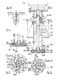
- the radial compression assembly (3) shown in FIG. I bis, comprises two U-shaped end pieces coated with P T F E (310), one or more elastic juxtaposed prestressed rods (320), a screw (330).
- the clearance (340) allows the piston (I) to move back towards the center.
- the invention thanks to these axial and radial clearance take-up devices, allows the following hydraulic operation.
- the rotation of the motor causes a modification of the volume of the Asp chambers. and Ref. causing the suction of the liquid entering the suction pipe and the simultaneous delivery in Ref.
- the pump is self-priming and can start dry, that is to say operate without the liquid having been previously introduced into the Asp chambers. and Ref. It is reversible, depending on the direction of rotation of the motor the Asp chambers. and Ref. are swapped and the direction of movement of the liquid reversed.
- the maximum hydraulic pressure obtained in the chamber Ref. is about 10 to 15 bar.
- This pressure is introduced into an annular chamber (I3) defined by the contacts (8) (I0) (2) (9). Self-sealing is thus obtained in contact with the front plate (10) on the piston (I) and the bottom (I2), that is to say that the greater the pressure in the chamber Ref. the greater the pressure in the chamber (I3) which ensures optimum volumetric and mechanical efficiency by balancing the forces on the plate (10)
- the present invention also aims to improve the sealing device of the friction-oscillating piston by lateral supports on the diaphragm (radial wall separating the suction orifice from the discharge).
- the backlash device overcomes these drawbacks. It is characterized in that the piston has an extendable slot in which is housed a metallic elastic element so that the diaphragm piston contact is permanent.
- the suction and discharge chambers are thus isolated from the bearing which does not have a wear compensation device. One can then easily, without risk of contaminating the transferred fluid, use an external fluid to lubricate the bearing.
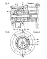
- FIG. 4 represents a longitudinal section of the device provided with such an improvement in combination with the first.
- FIG. 5 represents a cross section of the device of FIG. 4.
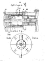
- Figure 6 shows a cross section of a variant of this device.
- the device shown in figs. 4 and 5 comprises the piston (I) in which it was made, at the periphery and along a generatrix, lips (17) and (I8) of rounded shapes sliding on a diaphragm (I9) of rectangular shape embedded in the body (2).
- an expandable slot (14) has been made in the piston comprising a circular housing (I6) receiving an elastic element (I5) permanently compressing the diaphragm (I9) between the lips (17 ) and (I8), removing the play in (17) existing in the first characteristic.
- the plate (I0) is modified (20) with a smaller internal diameter (2I).
- a circuit shown in Figure 4 is used to lubricate the bearing (4).
- FIG. 6 A variant of the device is shown in FIG. 6.
- the lips (17) and (I8) which provided a linear contact on the diaphragm have been replaced by 2 blades (22) ensuring a surface contact.
- a circular housing At the periphery of the piston (I) and according to a generator, a circular housing has been produced receiving the 2 oscillating blades (22) having a flat surface coming to bear on the diaphragm (I9).
- the third characteristic of the present invention relates to a device for improving the operation of the seal by friction on the shaft.
- the current seals operate either under vacuum or under pressure and in this case the wear is directly proportional to the pressure, any other parameter being maintained elsewhere (speed of rotation, fluid, temperature, etc.).
- the device according to this third characteristic in combination with the first, makes it possible to considerably reduce the wear of the seal despite a high discharge pressure.
- the piston places the suction chamber in communication with the rear of the mechanical seal. This is then subjected to an absolute pressure of I bar while the discharge pressure can be I0 bar and more. At rest, the static pressure acts at the rear of the mechanical seal which moves to come to bear against a stop mounted on the motor shaft. During a new operation, the seal resumes its place and its primary function.
- This device comprises the piston (I) which, driven by a circular oscillation movement, perfectly applies its lip (I8) on the discharge side to the diaphragm (I9) while the lip (I7 ) of the piston on the suction side connects the vacuum chamber with a washer (23) of the mechanical seal.
- the latter is composed of a counterface (24) made watertight on the rear plate. (I2) via a seal (25).
- This counterface (24) is free in translation but blocked in rotation by means of a screw-washer assembly (26).
- a rotating glass (27), sealed on the shaft (6) by means of a seal (28), is rotatably connected by a lug (29) to the shaft (6).
- An axial spring (30) ensures the initial pressing of the rotating glass (27) on the back face (24).
- a hole (3I) in the shaft (6) admits atmospheric pressure.
- a stop (32) mounted on the motor shaft limits the axial movement of the packing assembly.
- a sealing device is thus obtained, the operation of which is as follows. During the rotation of the piston (I) the vacuum exerted in the chamber Asp, passing between the diaphragm (I9) and the lip (17) of the piston, penetrates to the washer (23).
- the device allows application as a high pressure pump.
- the device according to this version making it possible to remedy this drawback, is characterized in that, in the assembly defined in the first version, the shaft is extended so as to receive a second piston.
- a rectifier properly directs the fluid from the outlet of the first piston to the second.
- the suction is always carried out on the first body, the repression being done on a second body.
- the device can be used as a rotary metering pump without valve.
- the device according to this characteristic makes it possible to increase the adjustment capacity of the rotary metering pumps, reaching I60 ° corresponding to 45% of displacement variation with excellent precision better than I% and always without valve.
- the device comprises an assembly defined as a first characteristic in which the body receives a rotary shutter making it possible to adjust the displacement of the pump using a pair of bevel gears and reading vernier.
- This device is characterized in that the body is perforated with recycling holes in the suction zone over I60 ° (variation in displacement) and no perforation in the delivery zone; an orifice at the end of the piston stroke ensures the escape of the liquid towards the delivery, seals ensure the peripheral and axial sealing between the suction and the delivery.
- the shutter (40) is drawn in an intermediate position between j and k.
- the liquid enters through the pipe Asp to come into the suction chamber defined by the contact of the piston (I) on the perforated body (39).
- the piston pushes the liquid into the delivery chamber.
- the latter cannot exit through the Ref tubing because it returns back through the holes (47) on the side of the delivery chamber of the body (39).
- the generatrix of contact perforated piston-body arrives at a point (48) corresponding to the end of the obturator (40) masking the holes, the liquid cannot go back because of the obturator and crosses the tubing Ref .
- the volume of the displacement defined by position (48) is intermediate.
- the device in combination with the first, possibly with the second and the third, is applicable to the production of a mixing group by centrifugal mobile with forced injection.
- the output speed decreases with increasing viscosity which limits the field of application of these devices.
- the device according to this sixth version linked to the first, 'making it possible to remedy this drawback is characterized in that the. flow speed ensured by the positive displacement pump supplying the impeller, is constant whatever the viscosity. The impeller is therefore necessarily profiled, no longer to ensure the flow rate, but to efficiently cross the flows.
- the device as shown in Figures 14 and 15 (with closed impeller) and Figures 16 and 17 for the open impeller variant, comprises an assembly defined by the first characteristic in which the shaft (6) has an extension (49 ) to receive a coupling sleeve (50) driving a main shaft (5I) on which is locked a closed (52) or open (56) impeller comprising six three-sided blades (521) in vertical planes integral with the partition median (522) with fins ⁇ 523) oriented once below, once above the horizontal and so on.
- This partition has holes (524).
- the impeller When the impeller is closed, it is associated with an "open cheek" in upper q (525) having a flange (526), the lower cheek (527) then closing the impeller and oriented holes (528) and (529 ) in the cheeks favoring the deviation of the jets and recycling.
- the assembly is closed by the cap (9) which is formed by an intermediate plate (53) on which is mounted a tube (54) supporting a bearing guide (55).
- Figure 18 shows the installation of the device object of Figures 14 to 17 comprising the tank and the assembly of pipes and valves.
- the pump sucks the liquid in (1) and discharges it in (n) in the support tube (54).
- the liquid divided by the holes in the grill the bearing support (55) arrives in the impeller (52) or (56).
- the Li-. that already present in the tank, enters (q) into the impeller.
- the flow crosses successively above and below the horizontal.
- the valve cock being oriented properly, the pump sucks the liquid in (m) and discharges it in (n) in the same way as above.
- valve plugs being oriented on p, m, where the tank is emptied through the pump.
- the device is applicable to continuous grinding.
- the device comprises an assembly defined by the first characteristic in which the shaft (6) has an extension (58) for receiving a booster screw (59) and a rotary scraper (60).
- An inner perforated body (6I) is mounted on a plate (62) receiving an outer body (63).
- a cap (6 4 ) closes the assembly.
- the operation is as follows.
- the non-homogeneous paste enters through the Asp tubing, is rotated by the feeding screw (59) which pushes it through the plate (62) into the chambers located between the piston and the body (6I).
- the piston crushes the dough which passes through the calibrated holes of the body (6I). Homogeneous, it is taken up by the scraper (60) to be evacuated by the tubing Ref.
- the device is applicable to continuous filtration.
- the device as shown in Figures 21 and 22, comprises an assembly defined by the first characteristic in which the ar bre (6) has an extension (65) for receiving a pinion (66) communicating its rotational movement to a brush (67) via a pinion (68).
- a tray (69) receives a filter element (70) and a body (71) closed by a cap (72).
- the operation is as follows.
- the liquid charged with solid particles enters through the pipe Asp.
- the clear liquid leaving the filter element (70) is directed to the pump and then the Ref tubing while the solid particles are entrained by the brush (67) in rotation towards the purge.
Landscapes
- Engineering & Computer Science (AREA)
- Mechanical Engineering (AREA)
- General Engineering & Computer Science (AREA)
- Reciprocating Pumps (AREA)
- Details Of Reciprocating Pumps (AREA)
Applications Claiming Priority (2)
| Application Number | Priority Date | Filing Date | Title |
|---|---|---|---|
| FR8600542 | 1986-01-16 | ||
| FR8600542A FR2592920B1 (fr) | 1986-01-16 | 1986-01-16 | Pompe volumetrique a multifonctions du type a piston oscillant. |
Publications (2)
| Publication Number | Publication Date |
|---|---|
| EP0236148A2 true EP0236148A2 (de) | 1987-09-09 |
| EP0236148A3 EP0236148A3 (de) | 1987-12-09 |
Family
ID=9331162
Family Applications (1)
| Application Number | Title | Priority Date | Filing Date |
|---|---|---|---|
| EP87400045A Withdrawn EP0236148A3 (de) | 1986-01-16 | 1987-01-12 | Mehrzweck-Kreiskolben-Verdrängungspumpe |
Country Status (2)
| Country | Link |
|---|---|
| EP (1) | EP0236148A3 (de) |
| FR (1) | FR2592920B1 (de) |
Families Citing this family (1)
| Publication number | Priority date | Publication date | Assignee | Title |
|---|---|---|---|---|
| RU2180258C1 (ru) * | 2001-03-30 | 2002-03-10 | Закрытое акционерное общество Инженерный научно-производственный центр "Союзводпроект" | Фильтр для очистки жидкости |
Family Cites Families (16)
| Publication number | Priority date | Publication date | Assignee | Title |
|---|---|---|---|---|
| FR529681A (fr) * | 1919-10-03 | 1921-12-03 | Machine à piston travailleur circulaire actionné excentriquement dans une enveloppe cylindrique | |
| US1482807A (en) * | 1921-08-31 | 1924-02-05 | Westinghouse Electric & Mfg Co | Regulator for rotary pumps and motors |
| FR855811A (fr) * | 1938-06-07 | 1940-05-21 | Compresseur à pistons rotatifs avec palettes montées centralement dans le carter du compresseur et solidaires les unes des autres | |
| FR54561E (fr) * | 1946-05-25 | 1950-05-04 | Perfectionnements aux pompes rotatives | |
| DE904985C (de) * | 1951-04-04 | 1954-02-25 | Alfred Richter | Stufenlos regelbares hydraulisches Zahnkorbkapseltriebwerk |
| FR1060137A (fr) * | 1952-07-03 | 1954-03-30 | Serrado Ets | Pompe, notamment pour matières épaisses |
| FR1141892A (fr) * | 1954-07-21 | 1957-09-11 | Pompe à piston animé d'un mouvement excentrique | |
| US2856860A (en) * | 1955-08-03 | 1958-10-21 | Mechanisms Company | Fluid pressure transducer with end clearance control |
| FR1208295A (fr) * | 1957-06-07 | 1960-02-23 | Machine, telle que pompe ou moteur à fluide sous pression, comportant des chambres et des pistons rotatifs | |
| US3202101A (en) * | 1963-07-05 | 1965-08-24 | American Brake Shoe Co | Method and means for preventing cavitation in hydraulic piston and vane pumps |
| DE1553092A1 (de) * | 1966-04-02 | 1970-12-03 | Horst Knapp | Kapselpumpe |
| FR1478849A (fr) * | 1966-05-05 | 1967-04-28 | Perfectionnements apportés aux pompes | |
| US3667878A (en) * | 1971-01-08 | 1972-06-06 | Ass Portland Cement | Pump construction |
| US3730656A (en) * | 1971-03-22 | 1973-05-01 | Dowty Technical Dev Ltd | Hydraulic apparatus |
| US3752609A (en) * | 1972-02-17 | 1973-08-14 | Sperry Rand Corp | Vane pump with fluid-biased end walls |
| GB2088958B (en) * | 1980-12-05 | 1983-11-23 | Plessey Co Ltd | A rotary pump for a liquid containing solid contaminants |
-
1986
- 1986-01-16 FR FR8600542A patent/FR2592920B1/fr not_active Expired
-
1987
- 1987-01-12 EP EP87400045A patent/EP0236148A3/de not_active Withdrawn
Also Published As
| Publication number | Publication date |
|---|---|
| FR2592920B1 (fr) | 1989-06-02 |
| FR2592920A1 (fr) | 1987-07-17 |
| EP0236148A3 (de) | 1987-12-09 |
Similar Documents
| Publication | Publication Date | Title |
|---|---|---|
| EP0654297B1 (de) | Anlage und Vorrichtung zum Mischen visköser Produkte und/oder Flüssigkeiten und Anwendung einer solchen Vorrichtung | |
| EP0368122B1 (de) | Mehrstufige Roots-Vakuumpumpe | |
| FR2559848A1 (fr) | Machine a volutes pour comprimer un fluide | |
| FR2485678A1 (fr) | Procede et mecanisme pour controler la pression aux parties assurant l'etancheite d'un arbre d'un dispositif et pompe de transport de fluide l'utilisant | |
| EP1006299A1 (de) | Dichtungsanordnung für rotierende Wellen | |
| EP3686427A1 (de) | Pumpe für flüssiges produkt, die eine dichtungsvorrichtung umfasst, und sprühanlage, die eine solche pumpe umfasst | |
| FR2675213A1 (fr) | Systeme formant barriere pour l'huile de lubrification des paliers d'un compresseur centrifuge muni de joints d'etancheite a labyrinthe installe dans un environnement confine. | |
| EP0044530A1 (de) | Elektrisches Pumpenaggregat mit Flügelkolben und Öldichtung | |
| FR2746452A1 (fr) | Dispositif d'entrainement rotatif etanche a excentricite, notamment pour pompe volumetrique | |
| EP0063062B1 (de) | Dichtung für Kreiselmaschine mit hydraulischer Flüssigkeit | |
| FR2558901A1 (fr) | Verin a mecanisme de prevention des fuites | |
| FR2829535A1 (fr) | Pompe a palettes a cylindree variable | |
| FR2702010A1 (fr) | Soupape de décharge pour compresseur à volutes. | |
| FR2716633A1 (fr) | Appareil à agitateur et tube d'aspiration. | |
| FR2565295A1 (fr) | Pompe a vide rotative etanchee dans l'huile | |
| FR2468770A1 (fr) | Compresseur a piston roulant | |
| CN213377262U (zh) | 卧式离心机的刮刀卸料机构 | |
| EP1893341B1 (de) | Vorrichtung und anlage zum spritzen eines beschichtungsprodukts mit einem behältnis | |
| MC219A1 (fr) | Rétroviseur | |
| EP0113278B1 (de) | Flüssigkeitspumpenvorrichtung, insbesondere für die Brennstoffzufuhr eines Brenners | |
| FR2520474A1 (fr) | Valve de surete destinee a la decharge et a la reconstitution d'un fluide | |
| EP0277852B1 (de) | Kolbenschmierungseinrichtung | |
| FR2912788A1 (fr) | Dispositif etanche de transmission d'un mouvement de rotation a l'interieur d'une chambre | |
| CH365477A (fr) | Dispositif pour obturer un orifice ménagé dans une paroi et traversé par une arbre rotatif | |
| BE486402A (de) |
Legal Events
| Date | Code | Title | Description |
|---|---|---|---|
| PUAI | Public reference made under article 153(3) epc to a published international application that has entered the european phase |
Free format text: ORIGINAL CODE: 0009012 |
|
| AK | Designated contracting states |
Kind code of ref document: A2 Designated state(s): BE DE ES GB IT NL |
|
| PUAL | Search report despatched |
Free format text: ORIGINAL CODE: 0009013 |
|
| AK | Designated contracting states |
Kind code of ref document: A3 Designated state(s): BE DE ES GB IT NL |
|
| 17P | Request for examination filed |
Effective date: 19880520 |
|
| 17Q | First examination report despatched |
Effective date: 19890208 |
|
| STAA | Information on the status of an ep patent application or granted ep patent |
Free format text: STATUS: THE APPLICATION IS DEEMED TO BE WITHDRAWN |
|
| 18D | Application deemed to be withdrawn |
Effective date: 19900801 |