EP0236178A1 - Antriebsvorrichtung für Vierradantrieb - Google Patents
Antriebsvorrichtung für Vierradantrieb Download PDFInfo
- Publication number
- EP0236178A1 EP0236178A1 EP87400186A EP87400186A EP0236178A1 EP 0236178 A1 EP0236178 A1 EP 0236178A1 EP 87400186 A EP87400186 A EP 87400186A EP 87400186 A EP87400186 A EP 87400186A EP 0236178 A1 EP0236178 A1 EP 0236178A1
- Authority
- EP
- European Patent Office
- Prior art keywords
- transmission device
- wheel drive
- drive transmission
- central differential
- flange
- Prior art date
- Legal status (The legal status is an assumption and is not a legal conclusion. Google has not performed a legal analysis and makes no representation as to the accuracy of the status listed.)
- Withdrawn
Links
Images


Classifications
-
- B—PERFORMING OPERATIONS; TRANSPORTING
- B60—VEHICLES IN GENERAL
- B60K—ARRANGEMENT OR MOUNTING OF PROPULSION UNITS OR OF TRANSMISSIONS IN VEHICLES; ARRANGEMENT OR MOUNTING OF PLURAL DIVERSE PRIME-MOVERS IN VEHICLES; AUXILIARY DRIVES FOR VEHICLES; INSTRUMENTATION OR DASHBOARDS FOR VEHICLES; ARRANGEMENTS IN CONNECTION WITH COOLING, AIR INTAKE, GAS EXHAUST OR FUEL SUPPLY OF PROPULSION UNITS IN VEHICLES
- B60K17/00—Arrangement or mounting of transmissions in vehicles
- B60K17/34—Arrangement or mounting of transmissions in vehicles for driving both front and rear wheels, e.g. four wheel drive vehicles
- B60K17/344—Arrangement or mounting of transmissions in vehicles for driving both front and rear wheels, e.g. four wheel drive vehicles having a transfer gear
- B60K17/346—Arrangement or mounting of transmissions in vehicles for driving both front and rear wheels, e.g. four wheel drive vehicles having a transfer gear the transfer gear being a differential gear
- B60K17/3462—Arrangement or mounting of transmissions in vehicles for driving both front and rear wheels, e.g. four wheel drive vehicles having a transfer gear the transfer gear being a differential gear with means for changing distribution of torque between front and rear wheels
- B60K17/3465—Arrangement or mounting of transmissions in vehicles for driving both front and rear wheels, e.g. four wheel drive vehicles having a transfer gear the transfer gear being a differential gear with means for changing distribution of torque between front and rear wheels self-actuated means, e.g. differential locked automatically by difference of speed
-
- F—MECHANICAL ENGINEERING; LIGHTING; HEATING; WEAPONS; BLASTING
- F16—ENGINEERING ELEMENTS AND UNITS; GENERAL MEASURES FOR PRODUCING AND MAINTAINING EFFECTIVE FUNCTIONING OF MACHINES OR INSTALLATIONS; THERMAL INSULATION IN GENERAL
- F16D—COUPLINGS FOR TRANSMITTING ROTATION; CLUTCHES; BRAKES
- F16D35/00—Fluid clutches in which the clutching is predominantly obtained by fluid adhesion
- F16D35/005—Fluid clutches in which the clutching is predominantly obtained by fluid adhesion with multiple lamellae
Definitions
- the present invention relates to a four-wheel drive transmission device, which apply in particular to passenger cars.
- Numerous four-wheel drive devices are known, which include a mechanism box at the outlet of the gearbox, in order to transmit the movement to the front axle, and to the rear axle. Each axle has a differential disposed between the wheels, which receives the movement of the mechanism box. Certain device also offers the presence of a differential between the front axle and the rear axle, this differential being arranged immediately at the outlet of the mechanism box. In order not to considerably increase fuel consumption, these mechanisms make it possible to operate either on two-wheel drive or four-wheel drive. This is why a command available to the driver makes it possible to switch to four-wheel drive. These devices have the disadvantage, when there are two driving wheels, of presenting a risk of loss of grip on a wheel.
- the object of the present invention is to provide a four-wheel drive transmission device, which makes it possible to make the clutching operation in four-wheel drive automatic; the device adapting perfectly to the grip conditions of each wheel of the vehicle.
- the transmission device according to the invention must have an architecture, which adapts very easily to the new structures of motor vehicles.
- the four-wheel drive transmission device comprises a secondary shaft, which is linked to the input of a central differential.
- An output from said central differential drives the drive pinion of the coaxial front axle, and is mounted inside said secondary shaft, said drive gear driving a crown secured to the front differential.
- the other output of the central differential drives a rear coaxial deflection shaft and in the extension of said drive pinion.
- a self-braking system is arranged on the movement outputs of the central differential. 1
- a self-braking system is arranged on the movement outputs of the front differential.
- a self-braking system is arranged on the movement outputs of the differential of the rear axle.
- the self-braking system is a viscous system.
- the self-braking system is a mechanical assembly with preload washers.
- the self-braking system is a mechanical assembly with axial compression springs.
- the engine and the gearbox are arranged longitudinally in the vehicle.
- the viscous system comprises a multi-disc assembly with a viscosity-controlled fluid, which is enclosed by a closure hub and having sealing means.
- the rear deflection shaft is linked to the transmission shaft to the hub of a coupling plate.
- the gearbox casing carries a rear casing, which receives a closing flange carrying the bearing of the rear deflection shaft, which is supported by the end of the drive pinion at the hub of a needle bearing.
- the four-wheel drive transmission device thus has the advantage of offering great security. Indeed, in case of loss of grip of any of the wheels, the transmission immediately changes to four-wheel drive. The driver's attention can thus be devoted solely to driving his vehicle, which considerably increases safety, especially in bad weather conditions.
- the entire device makes it possible to solve the problems posed by the architecture of the vehicle, and offers more flexibility in the possible arrangement of the various mechanical members.
- the four-wheel drive transmission device is disposed at the outlet of a gearbox 33, which is driven by a motor 32.
- this engine assembly 32 gearbox 33 is disposed longitudinally in the vehicle.
- the device according to the invention is mounted on a propulsion unit arranged at the front of the vehicle. It is obvious that this device could be applied to a rear propulsion unit, and in this case all that will be called front axle and rear axle in the following description would reciprocally become rear axle and front axle.
- the clutch is disposed in a clutch housing 30, which is fixed to the engine 32.
- the clutch housing 30 carries a gearbox housing 25.
- the gearbox housing 25 carries a rear housing 26 , which receives a closing flange 27.
- the entire device according to the invention is arranged in the housings 25, 26 and 27.
- the gearbox 33 includes a primary shaft 1 and a secondary shaft 2.
- the secondary shaft 2 is linked to the input of the central differential (4, 39).
- a movement output of the central differential 4 drives the drive pinion 3 of the crown 29 of the front axle whose axis is referenced 6.
- the other movement output of the central differential (4, 39) drives the plate d coupling 38 integral with the transmission shaft 34.
- a self-braking system is arranged between the movement outputs of the central differential (4, 39), so as to be able to automatically transfer part of the energy from the axle which would be in loss of grip on the other axle .
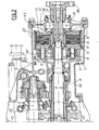
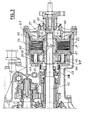
- the self-braking system is a viscous system 16 for FIG. 2 and a viscous system 31 for FIG. 3.
- a self-braking system of the mechanical assembly type with preload washers One could also provide as a self-braking system a mechanical assembly with axial compression springs.
- a self-braking system is arranged between the motion outputs of the front differential.
- the self-braking system arranged between the outputs of the central differential 4, 39 the self-braking system arranged between the outputs of the front differential or between the outputs of the rear axle differential, these self-braking systems are a viscous system.
- the secondary shaft 2 of the gearbox 33 is integral with the hub 8 of the ring gear 7 of the central differential 4.
- This planet carrier 12 is integral with a secondary axis 5, which is coaxial with the secondary shaft 2.
- This secondary axis 5 passes inside the shaft secondary 2, and it ends with the drive pinion 3.
- the other movement output of the central differential 4 is effected by the sun gear 10, which is integral with the rear deflection shaft 15.
- This rear deflection shaft 15 is itself secured in rotation by means of grooves in the coupling plate 38.
- This rear deflection shaft 15 is supported on the one hand by a bearing 35 mounted in the closing flange 27, and on the other hand by the end 36 of the drive pinion 3 and the secondary axis 5 by means of a roller t needle 37.
- the satellites 9 and 55 of the central differential 4 are mounted on axes 11, which are supported by the planet carrier 12 and, by a drive flange 14.
- the planet carrier 12 is integral with the secondary axis 5 by l 'intermediate its hub 13 which is connected to said secondary axis 5 by means of grooves.
- the groups of satellites 55 generate one by one with corresponding groups of satellites 9, and on the other hand with the crown 7 of the central differential 4.
- the groups of satellites 9 in turn generate with the planetary 10.
- the secondary shaft 2 is integral with the movement input of the central differential 39, which is done by the crown 57.
- a movement output of the central differential 39 is made by the sun gear 41 which is integral with a secondary axis 42 coaxial with the secondary shaft 2, and passing inside this secondary shaft 2.
- the secondary axis ends with the drive pinion 3.
- the other outlet movement of the central differential 39 is effected by the planet carrier 44 of said central differential 39.
- the planet carrier 44 is mounted inside the hub of the crown 57, by means of its hub 58.
- the satellites 45 and 56 of the central differential 39 are mounted on axes 46 supported by the planet carrier 44 and by the drive flange 47.
- a ring 53 is interposed between the hub 58 and the crown 57.
- a rear deflection shaft 50 is linked to the transmission shaft 34 by means of the coupling plate 38.
- This rear deflection shaft 50 is supported by a bearing 35 mounted in the closing flange 27.
- This rear deflection shaft 50 is also supported by the end 36 of the drive pinion 3 and the secondary axis 42 by means of a needle bearing 37.
Landscapes
- Engineering & Computer Science (AREA)
- Mechanical Engineering (AREA)
- General Engineering & Computer Science (AREA)
- Chemical & Material Sciences (AREA)
- Combustion & Propulsion (AREA)
- Transportation (AREA)
- Arrangement And Driving Of Transmission Devices (AREA)
Applications Claiming Priority (2)
| Application Number | Priority Date | Filing Date | Title |
|---|---|---|---|
| FR8601363A FR2593754B1 (fr) | 1986-01-31 | 1986-01-31 | Dispositif de transmission a quatre roues motrices |
| FR8601363 | 1986-01-31 |
Publications (1)
| Publication Number | Publication Date |
|---|---|
| EP0236178A1 true EP0236178A1 (de) | 1987-09-09 |
Family
ID=9331678
Family Applications (1)
| Application Number | Title | Priority Date | Filing Date |
|---|---|---|---|
| EP87400186A Withdrawn EP0236178A1 (de) | 1986-01-31 | 1987-01-27 | Antriebsvorrichtung für Vierradantrieb |
Country Status (4)
| Country | Link |
|---|---|
| US (1) | US4756381A (de) |
| EP (1) | EP0236178A1 (de) |
| CA (1) | CA1282262C (de) |
| FR (1) | FR2593754B1 (de) |
Cited By (4)
| Publication number | Priority date | Publication date | Assignee | Title |
|---|---|---|---|---|
| EP0264513B1 (de) * | 1985-09-03 | 1990-07-18 | Regie Nationale Des Usines Renault | Allradantriebsvorrichtung |
| FR2654993A1 (fr) * | 1989-11-24 | 1991-05-31 | Renault | Differentiel central. |
| FR2681015A1 (fr) * | 1991-09-06 | 1993-03-12 | Renault | Mecanisme de transmission a rapports etages pour vehicule a quatre roues motrices. |
| US6030312A (en) * | 1996-06-06 | 2000-02-29 | Rover Group Limited | Motor vehicle power train |
Families Citing this family (5)
| Publication number | Priority date | Publication date | Assignee | Title |
|---|---|---|---|---|
| AT390408B (de) * | 1986-10-21 | 1990-05-10 | Steyr Daimler Puch Ag | Antriebsanordnung fuer allradgetriebene kraftfahrzeuge |
| JP2577910B2 (ja) * | 1987-04-30 | 1997-02-05 | 富士重工業株式会社 | 四輪駆動車のトランスフア装置 |
| FR2695880B1 (fr) * | 1992-09-18 | 1994-10-21 | Renault | Ensemble de propulsion et de transmission longitudinal pour véhicule à quatre roues motrices. |
| FR2700302B1 (fr) * | 1993-01-08 | 1995-03-10 | Renault | Dispositif de transmission muni d'un doubleur de gamme pour véhicule à quatre roues motrices. |
| US5704866A (en) * | 1996-07-26 | 1998-01-06 | New Venture Gear, Inc. | Transmission for four-wheel drive vehicles |
Citations (7)
| Publication number | Priority date | Publication date | Assignee | Title |
|---|---|---|---|---|
| BE640950A (de) * | ||||
| GB453912A (en) * | 1934-03-15 | 1936-09-15 | Daimler Benz Ag | Improvements in and relating to motor vehicles |
| US2821868A (en) * | 1953-06-22 | 1958-02-04 | Benjamin F Gregory | Power transmission assembly |
| FR1431408A (fr) * | 1965-04-09 | 1966-03-11 | Tatra Np | Transmission pour voitures automobiles à deux essieux moteurs |
| US4245525A (en) * | 1978-02-01 | 1981-01-20 | National Mine Service Company | Limited slip differential |
| GB2057987A (en) * | 1979-07-26 | 1981-04-08 | Schuler Presses Ltd | Vehicle transmission |
| EP0068309A1 (de) * | 1981-06-26 | 1983-01-05 | Harry Ferguson Limited | Differentialgetriebe-Einheit |
Family Cites Families (4)
| Publication number | Priority date | Publication date | Assignee | Title |
|---|---|---|---|---|
| US3830116A (en) * | 1973-07-18 | 1974-08-20 | Borg Warner | Planetary differential for four wheel drive with automatic locking gear |
| US4452331A (en) * | 1980-11-13 | 1984-06-05 | American Motors Corporation | Vehicle axle |
| JPS57118927A (en) * | 1981-01-09 | 1982-07-24 | Nissan Motor Co Ltd | Four-wheel drive car |
| FR2589109B1 (fr) * | 1985-10-29 | 1990-10-12 | Renault | Dispositif de transmission a quatre roues motrices |
-
1986
- 1986-01-31 FR FR8601363A patent/FR2593754B1/fr not_active Expired - Lifetime
-
1987
- 1987-01-27 EP EP87400186A patent/EP0236178A1/de not_active Withdrawn
- 1987-01-30 CA CA000528634A patent/CA1282262C/fr not_active Expired - Lifetime
- 1987-02-02 US US07/014,851 patent/US4756381A/en not_active Expired - Fee Related
Patent Citations (7)
| Publication number | Priority date | Publication date | Assignee | Title |
|---|---|---|---|---|
| BE640950A (de) * | ||||
| GB453912A (en) * | 1934-03-15 | 1936-09-15 | Daimler Benz Ag | Improvements in and relating to motor vehicles |
| US2821868A (en) * | 1953-06-22 | 1958-02-04 | Benjamin F Gregory | Power transmission assembly |
| FR1431408A (fr) * | 1965-04-09 | 1966-03-11 | Tatra Np | Transmission pour voitures automobiles à deux essieux moteurs |
| US4245525A (en) * | 1978-02-01 | 1981-01-20 | National Mine Service Company | Limited slip differential |
| GB2057987A (en) * | 1979-07-26 | 1981-04-08 | Schuler Presses Ltd | Vehicle transmission |
| EP0068309A1 (de) * | 1981-06-26 | 1983-01-05 | Harry Ferguson Limited | Differentialgetriebe-Einheit |
Non-Patent Citations (1)
| Title |
|---|
| DESIGN ENGINEERING, février 1981, pages 49-50, London, GB: "Viscous coupling development for automotive transmissions" * |
Cited By (5)
| Publication number | Priority date | Publication date | Assignee | Title |
|---|---|---|---|---|
| EP0264513B1 (de) * | 1985-09-03 | 1990-07-18 | Regie Nationale Des Usines Renault | Allradantriebsvorrichtung |
| FR2654993A1 (fr) * | 1989-11-24 | 1991-05-31 | Renault | Differentiel central. |
| EP0430725A1 (de) * | 1989-11-24 | 1991-06-05 | Regie Nationale Des Usines Renault | Zwischendifferential |
| FR2681015A1 (fr) * | 1991-09-06 | 1993-03-12 | Renault | Mecanisme de transmission a rapports etages pour vehicule a quatre roues motrices. |
| US6030312A (en) * | 1996-06-06 | 2000-02-29 | Rover Group Limited | Motor vehicle power train |
Also Published As
| Publication number | Publication date |
|---|---|
| FR2593754A1 (fr) | 1987-08-07 |
| FR2593754B1 (fr) | 1990-09-07 |
| US4756381A (en) | 1988-07-12 |
| CA1282262C (fr) | 1991-04-02 |
Similar Documents
| Publication | Publication Date | Title |
|---|---|---|
| FR2516874A1 (fr) | Systeme de traction a quatre roues motrices pour un vehicule | |
| EP0264513B1 (de) | Allradantriebsvorrichtung | |
| FR2464163A1 (fr) | Embrayage d'essieu | |
| EP0265297A1 (de) | Differentialgetriebevorrichtung, insbesondere für Kraftfahrzeuge | |
| EP0048445B1 (de) | Differentialgetriebe | |
| FR2526729A1 (fr) | Ensemble de boite-transfert a differentiel inter-ponts pour vehicule a quatre roues motrices | |
| EP0236178A1 (de) | Antriebsvorrichtung für Vierradantrieb | |
| EP2210757B1 (de) | Fahrzeug und Antriebseinheit mit elektrischen Antriebsmotoren und Steuerungsverfahren | |
| FR2589109A1 (fr) | Dispositif de transmission a quatre roues motrices | |
| FR2539358A1 (fr) | Mecanisme d'entrainement des roues avant et arriere d'un vehicule a moteur | |
| FR2539356A1 (fr) | Disposition des mecanismes de transmission d'un vehicule a quatre roues motrices | |
| FR2631588A1 (fr) | Appareil de transmission d'energie, notamment pour vehicule a quatre roues motrices | |
| FR2613015A1 (fr) | Dispositif d'un rapport de vitesse supplementaire sur une boite de vitesses mecanique | |
| FR2695880A1 (fr) | Ensemble de propulsion et de transmission longitudinal pour véhicule à quatre roues motrices. | |
| FR2498533A1 (fr) | Transmission a quatre roues motrices pour vehicule | |
| FR2562000A1 (fr) | Dispositif de transmission a deux differentiels, pour vehicule a quatre roues motrices | |
| FR2700302A1 (fr) | Dispositif de transmission muni d'un doubleur de gamme pour véhicule à quatre roues motrices. | |
| FR2700303A1 (fr) | Dispositif de transmission crabotable pour véhicule à quatre roues motrices. | |
| EP0174889B1 (de) | Schmierungsanlage für eine Getriebeeinheit für Kraftwagen mit zwei Antriebswellen | |
| FR2690114A1 (fr) | Dispostiif d'entraînement de véhicule à quatre roues motrices. | |
| FR2486900A3 (fr) | Vehicule de travaux publics, du type tombereau | |
| EP2848497B1 (de) | Schwenkmechanismus für Militärfahrzeug | |
| FR2657309A1 (fr) | Groupe motopropulseur transversal equipe d'une prise de puissance. | |
| BE422153A (de) | ||
| FR2611613A1 (fr) | Dispositif de transmission a quatre roues motrices |
Legal Events
| Date | Code | Title | Description |
|---|---|---|---|
| PUAI | Public reference made under article 153(3) epc to a published international application that has entered the european phase |
Free format text: ORIGINAL CODE: 0009012 |
|
| 17P | Request for examination filed |
Effective date: 19870130 |
|
| AK | Designated contracting states |
Kind code of ref document: A1 Designated state(s): AT BE DE ES GB IT NL SE |
|
| 17Q | First examination report despatched |
Effective date: 19881212 |
|
| STAA | Information on the status of an ep patent application or granted ep patent |
Free format text: STATUS: THE APPLICATION HAS BEEN WITHDRAWN |
|
| 18W | Application withdrawn |
Withdrawal date: 19930226 |
|
| RIN1 | Information on inventor provided before grant (corrected) |
Inventor name: RENAUDIN, ALAIN |