EP0236185B1 - Dispositif de fixation d'un appui-tête sur un siège de véhicule - Google Patents
Dispositif de fixation d'un appui-tête sur un siège de véhicule Download PDFInfo
- Publication number
- EP0236185B1 EP0236185B1 EP87400205A EP87400205A EP0236185B1 EP 0236185 B1 EP0236185 B1 EP 0236185B1 EP 87400205 A EP87400205 A EP 87400205A EP 87400205 A EP87400205 A EP 87400205A EP 0236185 B1 EP0236185 B1 EP 0236185B1
- Authority
- EP
- European Patent Office
- Prior art keywords
- tube
- collar
- bar
- orifices
- headrest
- Prior art date
- Legal status (The legal status is an assumption and is not a legal conclusion. Google has not performed a legal analysis and makes no representation as to the accuracy of the status listed.)
- Expired
Links
- 230000003467 diminishing effect Effects 0.000 claims 1
- 230000000903 blocking effect Effects 0.000 description 2
- 230000002787 reinforcement Effects 0.000 description 2
- 238000003466 welding Methods 0.000 description 2
- 238000006073 displacement reaction Methods 0.000 description 1
- 238000005553 drilling Methods 0.000 description 1
- 230000037431 insertion Effects 0.000 description 1
- 238000003780 insertion Methods 0.000 description 1
- 210000000056 organ Anatomy 0.000 description 1
- 230000003014 reinforcing effect Effects 0.000 description 1
- 238000000926 separation method Methods 0.000 description 1
Images

Classifications
-
- B—PERFORMING OPERATIONS; TRANSPORTING
- B60—VEHICLES IN GENERAL
- B60N—SEATS SPECIALLY ADAPTED FOR VEHICLES; VEHICLE PASSENGER ACCOMMODATION NOT OTHERWISE PROVIDED FOR
- B60N3/00—Arrangements or adaptations of other passenger fittings, not otherwise provided for
-
- B—PERFORMING OPERATIONS; TRANSPORTING
- B60—VEHICLES IN GENERAL
- B60N—SEATS SPECIALLY ADAPTED FOR VEHICLES; VEHICLE PASSENGER ACCOMMODATION NOT OTHERWISE PROVIDED FOR
- B60N2/00—Seats specially adapted for vehicles; Arrangement or mounting of seats in vehicles
- B60N2/68—Seat frames
- B60N2/682—Joining means
-
- B—PERFORMING OPERATIONS; TRANSPORTING
- B60—VEHICLES IN GENERAL
- B60N—SEATS SPECIALLY ADAPTED FOR VEHICLES; VEHICLE PASSENGER ACCOMMODATION NOT OTHERWISE PROVIDED FOR
- B60N2/00—Seats specially adapted for vehicles; Arrangement or mounting of seats in vehicles
- B60N2/80—Head-rests
- B60N2/806—Head-rests movable or adjustable
- B60N2/809—Head-rests movable or adjustable vertically slidable
- B60N2/812—Head-rests movable or adjustable vertically slidable characterised by their locking devices
- B60N2/818—Head-rests movable or adjustable vertically slidable characterised by their locking devices with stepwise positioning
Definitions
- the head restraints commonly mounted on vehicle seat backs have two support rods provided with notches or notches which can easily be inserted into sleeves fixed laterally on the back frame tube and then be immobilized in position by means of 'A pin, or the like, engaging on the one hand in a slot of the sleeve and, on the other hand, in a notch or notch of the corresponding rod.
- Such an assembly is simple, but it presupposes beforehand the local lateral deformation of the armature tube then the precise welding of the sleeve so that its slot is in a well determined position, which is a delicate operation.
- the sleeve constitutes a projection on the armature tube and can consequently be troublesome in the absence of a headrest.
- these two orifices are not intended to receive the bar directly, but for mounting an intermediate sleeve ensuring its reception and its guidance.
- the sleeve is thus placed inside the seat frame and can be welded to the tube without any particular details, but it is still necessary to deform the armature tube and to fix the intermediate sleeve on it, which complicates the making.
- the object of the present invention is to remedy these drawbacks by providing a device for fixing head restraints which is simpler to produce and compact, and which eliminates the intermediate guide sleeve.
- the invention is characterized in that the armature tube further comprises, between the two orifices, which ensure reception and guiding of the bar, a hole for passage of a worn locking pin by a split sheath, locally covering the reinforcement tube.
- the split sheath is constituted by a cylinder portion, of plastic material, of internal diameter analogous to the external diameter of the armature tube and is pierced with a central hole coaxial with the upper orifice of the tube. reinforcement or insertion opening of the support bar. Thanks to this arrangement, it is no longer necessary to deform the tube or to weld an annex member to it.
- the holes in the armature tube can have any suitable shape corresponding to those of the headrest support bar, so that the invention can also allow the fixing of a headrest having two cylindrical bars. support than a headrest with only one rectangular and flat bar.
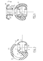
- the fixing device which is the subject of the invention is intended for mounting a headrest on the back of a seat, or more exactly for assembling the or each support bar 1 of this headrest on the upper tube 2 of the seat frame as shown in fig. 1.
- the tube 2 is pierced with two diametrically opposite orifices 4 and 6 respectively (fig. 2), each of these orifices having a shape similar to that of the cross section of the bar or rod 1 which can thus pass through them successively.
- a third orifice 8 is drilled in the wall of the tube 2 between the first two and is crossed by a lug 10 carried by the internal face of a sheath 12 locally covering the tube 2.
- the sheath 12 has the shape of a portion of cylinder whose internal diameter is substantially the same as that of the external surface of the tube 2 and covers most of this surface. Indeed, the longitudinal edges 14, 15 of this cylinder portion are located on either side of the lower orifice 6 of the tube 2 at a short distance from this orifice. Opposite the slot delimited by these edges 14 and 15 the sheath 12 has a central orifice 18 whose shape is exactly similar to that of the upper orifice 4 of the tube but which has a slightly larger dimension. Preferably, as shown in fig. 1, the sheath 12 has a maximum axial dimension in line with the hole 18, but this dimension is gradually reduced in the direction of the longitudinal edges 14 and 15 of the slot. As a result, the lug 10 starts from a relatively narrow part of this sheath 12.
- the establishment of the sheath 12 on the tube 2 is therefore carried out very simply by introducing the lug 10 into the hole 8, then tilting of the entire sheath 12, as indicated by the arrow F in FIG. 3, until it fully fits on the tube 2.
- the lug 10 having provided centering, the hole 18 is automatically placed around the orifice 4 of the tube 2, while the elasticity of the material which constitutes the sheath 12 joined to the shape of the latter ensures its tightening on the tube 2.
- each of the upper and lower orifices 4 and 6 of the tube 2 is reinforced by a sleeve 20, 22 projecting inside this tube.
- This sleeve can be attached and fixed, for example by welding, in the corresponding hole but, when the support bar 1 has a cylindrical shape it is often preferable to produce it at the same time. time that the orifice itself by a flow drilling operation of the tube 2.
- the support bar 1 of the headrest or each of the support bars, if the headrest is provided with several bars, has at least one notch or a blocking hole.
- the bar 1 comprises a succession of notches or notches 36 capable of receiving the lug 10 of the sheath 12.
- the bar 1 is in fact inserted into the orifices 4 and 6 of the tube 2 until the headrest reaches the desired height and the lug 10 enters the corresponding notch 36.
- the elasticity of the sheath 12 carrying the lug 10 allows the latter to be pushed outward during the axial displacement of the support rod 1 and to automatically fit into the corresponding notch, in order to block the headrest, when this movement stops.
- the force normally exerted on the headrest tends to consolidate this blocking.
- the device further comprises a guide sleeve 24 which is split axially at 25 and terminated at one of its ends by a conical head 6 forming an external shoulder 28 of cooperation with an internal shoulder 30 formed in the side wall of the hole 18 of the sleeve 12 (fig. 4).
- the socket 24 At its end opposite to the head 26 the socket 24 has a curved flange 32 whose concavity faces outwards, which clamps the padding of the backrest (not shown) between it and the sheath 12 and thus avoids any harmful contact between that -ci and the support bar 1.
- the fixing is reinforced by the presence of this guide sleeve 24 which, by cooperating with the support bar 1 and with the orifice 18, prevents any accidental tilting of the sleeve 12 relative to the tube 2, that is to say any separation of the fixing device organs.
Landscapes
- Engineering & Computer Science (AREA)
- Transportation (AREA)
- Mechanical Engineering (AREA)
- Aviation & Aerospace Engineering (AREA)
- Chair Legs, Seat Parts, And Backrests (AREA)
- Seats For Vehicles (AREA)
- Automobile Manufacture Line, Endless Track Vehicle, Trailer (AREA)
- Supports For Pipes And Cables (AREA)
- Fittings On The Vehicle Exterior For Carrying Loads, And Devices For Holding Or Mounting Articles (AREA)
Description
- Les appuis-tête couramment montés sur les dossiers de siège de véhicule comportent deux tiges de support munies d'encoches ou crans qui peuvent facilement être introduites dans des manchons fixés latéralement sur le tube d'armature du dossier puis être immobilisées en position au moyen d'une épingle, ou analogue, s'engageant d'une part dans une fente du manchon et, d'autre part, dans un cran ou encoche de la tige correspondante. Un tel montage est simple, mais il suppose préalablement la déformation latérale locale du tube d'armature puis le soudage précis du manchon pour que sa fente soit dans une position bien déterminée, ce qui est une opération délicate. En outre, le manchon constitue une saillie sur le tube d'armature et peut par suite être gênant en l'absence d'appui-tête.
- Il est par ailleurs connu, par exemple du brevet US-A-3 512 832, un dispositif pour la fixation, sur un siège, d'un appui-tête prolongé par au moins une barre de support munie d'encoches, traversant deux orifices opposés pratiqués coaxialement dans un tube d'armature du siège et comportant un organe de blocage coopérant avec l'une des encoches de la barre.
- Toutefois, ces deux orifices ne sont pas destinés à recevoir la barre directement, mais au montage d'un manchon intermédiaire assurant sa réception et son guidage.
- Le manchon est ainsi placé à l'intérieur de l'armature du siège et peut être soudé sur le tube sans précision particulière, mais il est encore nécessaire de déformer le tube d'armature et de fixer sur lui le manchon intermédiaire, ce qui complique la fabrication.
- La présente invention a pour but de remédier à ces inconvénients en fournissant un dispositif de fixation d'appuis-tête plus simple à réaliser et peu encombrant et qui supprime le manchon de guidage intermédiaire.
- Par rapport au dispositif connu, l'invention est caractérisée en ce que le tube d'armature comporte en outre, entre les deux orifices, qui assurent la réception et le guidage de la barre, un trou de passage d'un ergot de blocage porté par un fourreau fendu, recouvrant localement le tube d'armature.
- Selon une autre caractéristique, le fourreau fendu est constitué par une portion de cylindre, en matière plastique, de diamètre interne analogue au diamètre externe du tube d'armature et est percé d'un trou central coaxial à l'orifice supérieur du tube d'armature ou orifice d'introduction de la barre de support. Grâce à cette disposition, il n'est plus nécessaire de déformer le tube ni de souder un organe annexe sur lui.
- Bien entendu les orifices du tube d'armature peuvent avoir toutes formes appropriées correspondant à celles de la barre de support de l'appui-tête de sorte que l'invention peut permettre aussi bien la fixation d'un appui-tête ayant deux barres cylindriques de support que d'un appui-tête ne comportant qu'une seule barre rectangulaire et plate.
- La description ci-dessous d'un mode de réalisation, donné à titre d'exemple non limitatif et représenté aux dessins annexés, fera d'ailleurs ressortir les avantages et caractéristiques de l'invention.
- Sur les dessins:
- - la fig. 1 est une vue de côté d'un dispositif de fixation selon l'invention monté sur un tube d'armature et traversé par une barre de support d'appui-tête;
- - la fig. 2 est une vue en coupe suivant la ligne 2-2 de la fig. 1 ;
- - les fig. 3 et 4 sont des vues en coupe perpendiculaire au tube d'armature du dispositif de fixation de l'invention dans deux phases de montage successives.
- Le dispositif de fixation objet de l'invention est destiné au montage d'un appui-tête sur le dossier d'un siège, ou plus exactement à l'assemblage de la ou de chaque barre de support 1 de cet appui-tête sur le tube supérieur 2 de l'armature du siège ainsi que le montre la fig. 1. Dans ce but le tube 2 est percé de deux orifices diamétralement opposés respectivement 4 et 6 (fig. 2), chacun de ces orifices ayant une forme analogue à celle de la section droite de la barre ou tige 1 qui peut ainsi les traverser successivement. Un troisième orifice 8 est percé dans la paroi du tube 2 entre les deux premiers et est traversé par un ergot 10 porté par la face interne d'un fourreau 12 recouvrant localement le tube 2.
- Le fourreau 12 a la forme d'une portion de cylindre dont le diamètre interne est sensiblement le même que celui de la surface externe du tube 2 et recouvre la plus grande partie de cette surface. En effet, les bords longitudinaux 14, 15 de cette portion de cylindre se trouvent de part et d'autre de l'orifice inférieur 6 du tube 2 à une courte distance de cet orifice. A l'opposé de la fente délimitée par ces bords 14 et 15 le fourreau 12 comporte un orifice central 18 dont la forme est exactement semblable à celle de l'orifice supérieur 4 du tube mais qui a une dimension légèrement plus grande. De préférence, comme le montre la fig. 1, le fourreau 12 a une dimension axiale maximale au droit du trou 18 mais cette dimension se réduit progressivement en direction des bords longitudinaux 14 et 15 de la fente. Par suite, l'ergot 10 part d'une partie relativement étroite de ce fourreau 12.
- La mise en place du fourreau 12 sur le tube 2 s'effectue donc très simplement par introduction de l'ergot 10 dans le trou 8, puis basculement de l'ensemble du fourreau 12, comme indiqué par la flèche F sur la fig. 3, jusqu'à son complet emboîtement sur le tube 2. L'ergot 10 ayant assuré le centrage, le trou 18 se place automatiquement autour de l'orifice 4 du tube 2, tandis que l'élasticité de la matière qui constitue le fourreau 12 jointe à la forme de ce dernier assure son serrage sur le tube 2.
- De préférence, chacun des orifices supérieur et inférieur 4 et 6 du tube 2 est renforcé par un manchon 20, 22 en saillie à l'intérieur de ce tube. Ce manchon peut être rapporté et fixé, par exemple par soudage, dans l'orifice correspondant mais, lorsque la barre de support 1 a une forme cylindrique il est souvent préférable de le réaliser en même temps que l'orifice lui-même par une opération de fluoperçage du tube 2.
- Bien entendu, la barre de support 1 de l'appui-tête ou chacune des barres de support, si l'appui-tête est muni de plusieurs barres, comporte au moins une encoche ou un trou de blocage. De préférence, comme représenté sur la fig. 2, la barre 1 comporte une succession d'encoches ou crans 36 susceptibles de recevoir l'ergot 10 du fourreau 12. Lors de la mise en place de l'appui-tête, la barre 1 est en effet enfoncée dans les orifices 4 et 6 du tube 2 jusqu'au moment où l'appui-tête atteint la hauteur désirée et où l'ergot 10 pénètre dans l'encoche 36 correspondante. L'élasticité du fourreau 12 portant l'ergot 10 permet à ce dernier d'être repoussé vers l'extérieur lors du déplacement axial de la tige-support 1 et de s'emboîter automatiquement dans l'encoche correspondante, afin de bloquer l'appui-tête, lorsque ce déplacement s'arrête. Par ailleurs, l'effort normalement exercé sur l'appui-tête tend à consolider ce blocage.
- Selon un mode de réalisation préféré, le dispositif comporte en outre une douille de guidage 24 qui est fendue axialement en 25 et terminée à l'une de ses extrémités par une tête conique 6 formant un épaulement extérieur 28 de coopération avec un épaulement intérieur 30 ménagé dans la paroi latérale du trou 18 du fourreau 12 (fig. 4). A son extrémité opposée à la tête 26 la douille 24 comporte une collerette incurvée 32 dont la concavité est tournée vers l'extérieur, qui pince entre elle et le fourreau 12 le rembourrage du dossier (non représenté) et évite ainsi tout contact nuisible entre celui-ci et la barre de support 1.
- La fixation est renforcée par la présence de cette douille de guidage 24 qui en coopérant avec la barre de support 1 et avec l'orifice 18 interdit tout basculement accidentel du fourreau 12 par rapport au tube 2, c'est-à-dire toute séparation des organes du dispositif de fixation.
- On obtient donc un assemblage sûr de la ou des barres de support d'un appui-tête directement sur le tube d'armature du siège, qui contribue à la fois au guidage et au verrouillage, en n'utilisant qu'un très petit nombre d'éléments faciles à réaliser qui peuvent être rapidement assemblés les uns aux autres et présentent un encombrement faible.
Claims (8)
Priority Applications (1)
| Application Number | Priority Date | Filing Date | Title |
|---|---|---|---|
| AT87400205T ATE42071T1 (de) | 1986-02-11 | 1987-01-29 | Vorrichtung zum befestigen einer kopfstuetze auf einen fahrzeugsitz. |
Applications Claiming Priority (2)
| Application Number | Priority Date | Filing Date | Title |
|---|---|---|---|
| FR8601845A FR2594078B1 (fr) | 1986-02-11 | 1986-02-11 | Dispositif de fixation d'un appui-tete sur un siege de vehicule |
| FR8601845 | 1986-02-11 |
Publications (2)
| Publication Number | Publication Date |
|---|---|
| EP0236185A1 EP0236185A1 (fr) | 1987-09-09 |
| EP0236185B1 true EP0236185B1 (fr) | 1989-04-12 |
Family
ID=9332013
Family Applications (1)
| Application Number | Title | Priority Date | Filing Date |
|---|---|---|---|
| EP87400205A Expired EP0236185B1 (fr) | 1986-02-11 | 1987-01-29 | Dispositif de fixation d'un appui-tête sur un siège de véhicule |
Country Status (10)
| Country | Link |
|---|---|
| US (1) | US4679850A (fr) |
| EP (1) | EP0236185B1 (fr) |
| JP (1) | JPH0683688B2 (fr) |
| KR (1) | KR870007801A (fr) |
| AT (1) | ATE42071T1 (fr) |
| CA (1) | CA1270180A (fr) |
| DE (1) | DE3760097D1 (fr) |
| ES (1) | ES2008696B3 (fr) |
| FR (1) | FR2594078B1 (fr) |
| MX (1) | MX160484A (fr) |
Families Citing this family (21)
| Publication number | Priority date | Publication date | Assignee | Title |
|---|---|---|---|---|
| DE3722856A1 (de) * | 1987-07-10 | 1989-01-19 | Keiper Recaro Gmbh Co | Hoehenverstelleinrichtung fuer kopfstuetzen von fahrzeugsitzen |
| US4976493A (en) * | 1989-02-27 | 1990-12-11 | Frankila John W | Vehicle headrest post guide |
| US5080437A (en) * | 1990-12-17 | 1992-01-14 | Chrysler Corporation | Self-adjusting headrest guide arrangement |
| CA2034924C (fr) * | 1991-01-25 | 1995-12-05 | Dennis Brothers | Ferrure a crans pour dossier de siege d'automobile |
| US5228183A (en) * | 1991-04-16 | 1993-07-20 | Tachi-S. Co., Ltd. | Arrangement and method for securing headrest stay in seat |
| US6823575B2 (en) * | 1997-04-25 | 2004-11-30 | Bend All Automotive Incorporated | Securement of head rest support into automobile seat frame |
| US5816658A (en) * | 1997-05-23 | 1998-10-06 | Flexsteel Industries, Inc. | Head rest lock |
| ATE208666T1 (de) * | 1998-07-21 | 2001-11-15 | Garconnet Ets | Verfahren zum herstellen von rastnuten in rohren, sowie durch das verfahren hergestellten rohre |
| US6309134B1 (en) | 1999-11-18 | 2001-10-30 | Illinois Tool Works, Inc. | Retainer catch assembly |
| ES2283664T3 (es) * | 2002-02-15 | 2007-11-01 | Grammer Automotive Gmbh | Reposacabezas para asientos de vehiculos. |
| US7137668B2 (en) * | 2003-04-29 | 2006-11-21 | Intier Automotive Inc. | Multi-position head restraint |
| US7086701B2 (en) * | 2004-01-13 | 2006-08-08 | Intier Automotive Inc. | Head restraint guide system |
| US7309108B2 (en) * | 2004-11-22 | 2007-12-18 | Tachi-S Co., Ltd. | Headrest device for vehicle seat |
| DE102007010064B4 (de) * | 2007-02-28 | 2016-02-04 | Faurecia Autositze Gmbh | Fahrzeugsitz mit einer Kopfstütze |
| DE102010064068A1 (de) | 2010-12-23 | 2012-06-28 | Volkswagen Ag | Tragelement, insbesondere Tragstange für eine Kopfstütze mit Kopfstützen-Rastkerben mit verringerter Kerbwirkung |
| US9079519B2 (en) | 2012-05-31 | 2015-07-14 | Bae Industries, Inc. | Assembly and method for compressive swaging side frames to a package supporting housing associated with a forward dump vehicle headrest |
| KR101393789B1 (ko) * | 2012-09-06 | 2014-05-12 | 현대자동차주식회사 | 헤드레스트 폴가이드 |
| DE102016000572A1 (de) * | 2016-01-22 | 2017-07-27 | Grammer Ag | Tragvorrichtung einer Kopfstütze, Kopfstütze und Verfahren zur Herstellung einer Tragvorrichtung |
| FR3047208B1 (fr) * | 2016-01-29 | 2019-05-03 | Faurecia Sieges D'automobile | Broche d'appui-tete et appui-tete de siege |
| GB2566060B (en) * | 2017-09-01 | 2020-04-01 | Jaguar Land Rover Ltd | Head restraint apparatus for a vehicle and method |
| CN112040811B (zh) * | 2018-08-06 | 2024-09-27 | 岱美北美汽车股份有限公司 | 包括减少bsr的锁定构造的头枕组件 |
Family Cites Families (6)
| Publication number | Priority date | Publication date | Assignee | Title |
|---|---|---|---|---|
| US3512833A (en) * | 1967-08-11 | 1970-05-19 | Toyota Motor Co Ltd | Adjustable head rest for vehicle seats |
| US3512832A (en) * | 1967-08-23 | 1970-05-19 | Toyota Motor Co Ltd | Head-rest for the seat of vehicles |
| US3498672A (en) * | 1968-03-05 | 1970-03-03 | L F Grammes & Sons Inc | Vehicle headrest construction |
| DE2426728A1 (de) * | 1974-06-01 | 1975-12-11 | Bayerische Motoren Werke Ag | Vorrichtung zum arretieren einer hoehenverstellbaren kopfstuetze |
| GB2034581A (en) * | 1978-10-20 | 1980-06-11 | Hallam Sleigh & Cheston Ltd | Vehicle seat assemblies |
| US4577837A (en) * | 1984-07-30 | 1986-03-25 | Marvin Berg | Locking mechanism for extendible telescoping tubular members |
-
1986
- 1986-02-11 FR FR8601845A patent/FR2594078B1/fr not_active Expired
- 1986-06-13 US US06/873,928 patent/US4679850A/en not_active Expired - Fee Related
-
1987
- 1987-01-29 ES ES87400205T patent/ES2008696B3/es not_active Expired
- 1987-01-29 DE DE8787400205T patent/DE3760097D1/de not_active Expired
- 1987-01-29 EP EP87400205A patent/EP0236185B1/fr not_active Expired
- 1987-01-29 AT AT87400205T patent/ATE42071T1/de not_active IP Right Cessation
- 1987-02-09 KR KR870001019A patent/KR870007801A/ko not_active Withdrawn
- 1987-02-09 CA CA000529268A patent/CA1270180A/fr not_active Expired - Lifetime
- 1987-02-09 MX MX5185A patent/MX160484A/es unknown
- 1987-02-10 JP JP62029472A patent/JPH0683688B2/ja not_active Expired - Lifetime
Also Published As
| Publication number | Publication date |
|---|---|
| CA1270180C (fr) | 1990-06-12 |
| US4679850A (en) | 1987-07-14 |
| JPH0683688B2 (ja) | 1994-10-26 |
| DE3760097D1 (en) | 1989-05-18 |
| JPS62204709A (ja) | 1987-09-09 |
| ES2008696B3 (es) | 1989-08-01 |
| FR2594078B1 (fr) | 1988-05-27 |
| EP0236185A1 (fr) | 1987-09-09 |
| MX160484A (es) | 1990-03-02 |
| ATE42071T1 (de) | 1989-04-15 |
| CA1270180A (fr) | 1990-06-12 |
| KR870007801A (ko) | 1987-09-21 |
| FR2594078A1 (fr) | 1987-08-14 |
Similar Documents
| Publication | Publication Date | Title |
|---|---|---|
| EP0236185A1 (fr) | Dispositif de fixation d'un appui-tête sur un siège de véhicule | |
| FR2578299A1 (fr) | Dispositif de blocage d'une tige pour empecher tous mouvements d'extension et de contraction de celle-ci | |
| EP0315504B1 (fr) | Siège de véhicule automobile comportant des ailes latérales | |
| EP0604286A1 (fr) | Dispositif de liaison entre deux pièces mécaniques | |
| EP0053970B1 (fr) | Dispositif d'assemblage directionnel entre les éléments, notamment tubulaires, d'un échafaudage | |
| EP0318346A1 (fr) | Dispositif de fixation d'un revêtement notamment un revêtement de siège | |
| FR2797208A1 (fr) | Element antivibrations pourvu d'une surete d'arrachement | |
| FR2681918A1 (fr) | Dispositif pour l'assemblage et le desassemblage rapide de deux pieces l'une sur l'autre. | |
| EP3114969B1 (fr) | Tringle télescopique | |
| EP0252783A2 (fr) | Dispositif de rappel de la coiffe d'un siège de véhicule automobile | |
| EP0937907B1 (fr) | Dispositif de liaison, à une pièce extérieure, d'un noyau d'armature intérieure d'une articulation élastique | |
| FR2667275A1 (fr) | Dispositif de fixation d'un radiateur de refroidissement d'un moteur de vehicule automobile. | |
| FR2526499A1 (fr) | Joint pour barres contigues faisant partie de structures de type reticulaire ou a rayonnages, permettant d'eviter des parties de plus grand diametre | |
| EP0839245B1 (fr) | Gache destinee a une serrure notamment d'ascenseur | |
| FR2704606A1 (fr) | Bride à souder pour assemblages tubulaires. | |
| FR2547845A1 (fr) | Barriere de circulation multidirectionnelle | |
| FR2615230A1 (fr) | Dispositif monte sur un pieu de cloture pour la fixation d'un fil tendu | |
| EP2009204B1 (fr) | Ensemble pour grille barreaudée et outil d'assemblage correspondant. | |
| FR2757789A1 (fr) | Dispositif de fixation d'une platine d'un systeme d'essuyage de vehicule automobile | |
| EP0669431A1 (fr) | Système pour poutres | |
| FR2807366A1 (fr) | Dispositif de verrouillage a billes notamment pour l'ancrage d'un siege sur le plancher d'un vehicule automobile | |
| FR2695361A1 (fr) | Système de montage réglable d'un dispositif d'éclairage ou de signalisation de véhicule automobile sur une partie fixe solidaire du véhicule et dispositif ainsi équipé. | |
| EP1637747B1 (fr) | Agencement de fixation d'un élèment d'équipement pour véhicule automobile | |
| FR2751595A1 (fr) | Procede de montage d'un siege sur le plancher d'un vehicule, et piece pour sa mise en oeuvre | |
| FR2683249A1 (fr) | Piquet pour cloture. |
Legal Events
| Date | Code | Title | Description |
|---|---|---|---|
| PUAI | Public reference made under article 153(3) epc to a published international application that has entered the european phase |
Free format text: ORIGINAL CODE: 0009012 |
|
| AK | Designated contracting states |
Kind code of ref document: A1 Designated state(s): AT BE CH DE ES GB IT LI LU NL SE |
|
| 17P | Request for examination filed |
Effective date: 19870806 |
|
| 17Q | First examination report despatched |
Effective date: 19880203 |
|
| GRAA | (expected) grant |
Free format text: ORIGINAL CODE: 0009210 |
|
| RAP1 | Party data changed (applicant data changed or rights of an application transferred) |
Owner name: ECIA - EQUIPEMENTS ET COMPOSANTS POUR L'INDUSTRIE |
|
| AK | Designated contracting states |
Kind code of ref document: B1 Designated state(s): AT BE CH DE ES GB IT LI LU NL SE |
|
| REF | Corresponds to: |
Ref document number: 42071 Country of ref document: AT Date of ref document: 19890415 Kind code of ref document: T |
|
| ITF | It: translation for a ep patent filed | ||
| REF | Corresponds to: |
Ref document number: 3760097 Country of ref document: DE Date of ref document: 19890518 |
|
| GBT | Gb: translation of ep patent filed (gb section 77(6)(a)/1977) | ||
| PLBE | No opposition filed within time limit |
Free format text: ORIGINAL CODE: 0009261 |
|
| STAA | Information on the status of an ep patent application or granted ep patent |
Free format text: STATUS: NO OPPOSITION FILED WITHIN TIME LIMIT |
|
| 26N | No opposition filed | ||
| PGFP | Annual fee paid to national office [announced via postgrant information from national office to epo] |
Ref country code: AT Payment date: 19901227 Year of fee payment: 5 |
|
| PGFP | Annual fee paid to national office [announced via postgrant information from national office to epo] |
Ref country code: LU Payment date: 19910108 Year of fee payment: 5 |
|
| PGFP | Annual fee paid to national office [announced via postgrant information from national office to epo] |
Ref country code: CH Payment date: 19910110 Year of fee payment: 5 |
|
| PGFP | Annual fee paid to national office [announced via postgrant information from national office to epo] |
Ref country code: BE Payment date: 19910214 Year of fee payment: 5 |
|
| EPTA | Lu: last paid annual fee | ||
| PG25 | Lapsed in a contracting state [announced via postgrant information from national office to epo] |
Ref country code: LU Free format text: LAPSE BECAUSE OF NON-PAYMENT OF DUE FEES Effective date: 19920129 Ref country code: AT Effective date: 19920129 |
|
| ITTA | It: last paid annual fee | ||
| PG25 | Lapsed in a contracting state [announced via postgrant information from national office to epo] |
Ref country code: LI Effective date: 19920131 Ref country code: CH Effective date: 19920131 Ref country code: BE Effective date: 19920131 |
|
| BERE | Be: lapsed |
Owner name: EQUIPEMENTS ET COMPOSANTS POUR L'INDUSTRIE AUTOMOB Effective date: 19920131 |
|
| REG | Reference to a national code |
Ref country code: CH Ref legal event code: PL |
|
| REG | Reference to a national code |
Ref country code: GB Ref legal event code: 732 |
|
| ITPR | It: changes in ownership of a european patent |
Owner name: CESSIONE;CESA - COMPAGNIE EUROPEENNE DE SIEGES POU |
|
| REG | Reference to a national code |
Ref country code: ES Ref legal event code: PC2A Owner name: CESA-COMPAGNIE EUROPEENNE DE SIEGES POUR AUTOMOBIL |
|
| NLS | Nl: assignments of ep-patents |
Owner name: CESA-COMPAGNIE EUROPEENNE DE SIEGES POUR AUTOMOBIL |
|
| EAL | Se: european patent in force in sweden |
Ref document number: 87400205.8 |
|
| PGFP | Annual fee paid to national office [announced via postgrant information from national office to epo] |
Ref country code: NL Payment date: 19961223 Year of fee payment: 11 |
|
| PGFP | Annual fee paid to national office [announced via postgrant information from national office to epo] |
Ref country code: DE Payment date: 19961227 Year of fee payment: 11 |
|
| PGFP | Annual fee paid to national office [announced via postgrant information from national office to epo] |
Ref country code: ES Payment date: 19970113 Year of fee payment: 11 |
|
| PGFP | Annual fee paid to national office [announced via postgrant information from national office to epo] |
Ref country code: GB Payment date: 19970121 Year of fee payment: 11 |
|
| PGFP | Annual fee paid to national office [announced via postgrant information from national office to epo] |
Ref country code: SE Payment date: 19970123 Year of fee payment: 11 |
|
| PG25 | Lapsed in a contracting state [announced via postgrant information from national office to epo] |
Ref country code: GB Free format text: LAPSE BECAUSE OF NON-PAYMENT OF DUE FEES Effective date: 19980129 |
|
| PG25 | Lapsed in a contracting state [announced via postgrant information from national office to epo] |
Ref country code: SE Free format text: LAPSE BECAUSE OF NON-PAYMENT OF DUE FEES Effective date: 19980130 Ref country code: ES Free format text: LAPSE BECAUSE OF NON-PAYMENT OF DUE FEES Effective date: 19980130 |
|
| PG25 | Lapsed in a contracting state [announced via postgrant information from national office to epo] |
Ref country code: NL Free format text: LAPSE BECAUSE OF NON-PAYMENT OF DUE FEES Effective date: 19980801 |
|
| GBPC | Gb: european patent ceased through non-payment of renewal fee |
Effective date: 19980129 |
|
| NLV4 | Nl: lapsed or anulled due to non-payment of the annual fee |
Effective date: 19980801 |
|
| PG25 | Lapsed in a contracting state [announced via postgrant information from national office to epo] |
Ref country code: DE Free format text: LAPSE BECAUSE OF NON-PAYMENT OF DUE FEES Effective date: 19981001 |
|
| EUG | Se: european patent has lapsed |
Ref document number: 87400205.8 |
|
| REG | Reference to a national code |
Ref country code: ES Ref legal event code: FD2A Effective date: 20000403 |
|
| PG25 | Lapsed in a contracting state [announced via postgrant information from national office to epo] |
Ref country code: IT Free format text: LAPSE BECAUSE OF NON-PAYMENT OF DUE FEES;WARNING: LAPSES OF ITALIAN PATENTS WITH EFFECTIVE DATE BEFORE 2007 MAY HAVE OCCURRED AT ANY TIME BEFORE 2007. THE CORRECT EFFECTIVE DATE MAY BE DIFFERENT FROM THE ONE RECORDED. Effective date: 20050129 |