EP0236244A1 - Wärmerekuperator für offene Kamine - Google Patents
Wärmerekuperator für offene Kamine Download PDFInfo
- Publication number
- EP0236244A1 EP0236244A1 EP87420042A EP87420042A EP0236244A1 EP 0236244 A1 EP0236244 A1 EP 0236244A1 EP 87420042 A EP87420042 A EP 87420042A EP 87420042 A EP87420042 A EP 87420042A EP 0236244 A1 EP0236244 A1 EP 0236244A1
- Authority
- EP
- European Patent Office
- Prior art keywords
- plate
- heat recovery
- recovery device
- side walls
- extension
- Prior art date
- Legal status (The legal status is an assumption and is not a legal conclusion. Google has not performed a legal analysis and makes no representation as to the accuracy of the status listed.)
- Withdrawn
Links
- 238000011084 recovery Methods 0.000 title claims abstract description 26
- 238000002485 combustion reaction Methods 0.000 claims description 11
- 230000000295 complement effect Effects 0.000 claims description 8
- 239000011324 bead Substances 0.000 claims description 5
- 238000007789 sealing Methods 0.000 claims description 5
- 230000000630 rising effect Effects 0.000 claims description 4
- 239000000779 smoke Substances 0.000 claims description 3
- PZZOEXPDTYIBPI-UHFFFAOYSA-N 2-[[2-(4-hydroxyphenyl)ethylamino]methyl]-3,4-dihydro-2H-naphthalen-1-one Chemical compound C1=CC(O)=CC=C1CCNCC1C(=O)C2=CC=CC=C2CC1 PZZOEXPDTYIBPI-UHFFFAOYSA-N 0.000 claims 1
- 239000003517 fume Substances 0.000 claims 1
- 230000003068 static effect Effects 0.000 claims 1
- 238000007373 indentation Methods 0.000 abstract 1
- 238000009434 installation Methods 0.000 description 5
- 230000006978 adaptation Effects 0.000 description 4
- 230000008859 change Effects 0.000 description 4
- 239000004071 soot Substances 0.000 description 4
- 230000006870 function Effects 0.000 description 3
- 238000000465 moulding Methods 0.000 description 3
- 239000000446 fuel Substances 0.000 description 2
- 238000012423 maintenance Methods 0.000 description 2
- 230000016776 visual perception Effects 0.000 description 2
- 238000009825 accumulation Methods 0.000 description 1
- 230000008901 benefit Effects 0.000 description 1
- 230000015572 biosynthetic process Effects 0.000 description 1
- 238000004140 cleaning Methods 0.000 description 1
- 239000000567 combustion gas Substances 0.000 description 1
- 238000010276 construction Methods 0.000 description 1
- 230000000694 effects Effects 0.000 description 1
- 239000003546 flue gas Substances 0.000 description 1
- 230000005484 gravity Effects 0.000 description 1
- 238000003780 insertion Methods 0.000 description 1
- 230000037431 insertion Effects 0.000 description 1
- 239000000463 material Substances 0.000 description 1
- 238000012986 modification Methods 0.000 description 1
- 230000004048 modification Effects 0.000 description 1
- 230000002093 peripheral effect Effects 0.000 description 1
- 230000005855 radiation Effects 0.000 description 1
- 230000008439 repair process Effects 0.000 description 1
- 239000007787 solid Substances 0.000 description 1
- 239000004449 solid propellant Substances 0.000 description 1
- 238000009423 ventilation Methods 0.000 description 1
- 239000002023 wood Substances 0.000 description 1
Images
Classifications
-
- F—MECHANICAL ENGINEERING; LIGHTING; HEATING; WEAPONS; BLASTING
- F24—HEATING; RANGES; VENTILATING
- F24B—DOMESTIC STOVES OR RANGES FOR SOLID FUELS; IMPLEMENTS FOR USE IN CONNECTION WITH STOVES OR RANGES
- F24B1/00—Stoves or ranges
- F24B1/02—Closed stoves
- F24B1/022—Closed stoves easily collapsible or easily removable
-
- F—MECHANICAL ENGINEERING; LIGHTING; HEATING; WEAPONS; BLASTING
- F24—HEATING; RANGES; VENTILATING
- F24B—DOMESTIC STOVES OR RANGES FOR SOLID FUELS; IMPLEMENTS FOR USE IN CONNECTION WITH STOVES OR RANGES
- F24B1/00—Stoves or ranges
- F24B1/18—Stoves with open fires, e.g. fireplaces
- F24B1/1806—Mounting of closed stoves in a fireplace
-
- F—MECHANICAL ENGINEERING; LIGHTING; HEATING; WEAPONS; BLASTING
- F24—HEATING; RANGES; VENTILATING
- F24B—DOMESTIC STOVES OR RANGES FOR SOLID FUELS; IMPLEMENTS FOR USE IN CONNECTION WITH STOVES OR RANGES
- F24B1/00—Stoves or ranges
- F24B1/18—Stoves with open fires, e.g. fireplaces
- F24B1/191—Component parts; Accessories
- F24B1/195—Fireboxes; Frames; Hoods; Heat reflectors
Definitions
- the present invention relates to heat recovery devices, the construction of which is based on the principle of reducing heat losses due to radiation and convection.
- recuperators designed to be inserted in open hearths of traditional fireplaces likely to use one or more fuels in the solid state and, more generally, wood.
- a heat recovery device constructed for the above purposes, generally and usually comprises a first box, the upper hearth wall of which comprises a grid giving access to an ashtray disposed in the box.
- the grid consists of exchange tubes supporting the embers and crossed by an air circulation taking calories. Hot air is released into the room.
- the air circulation can be natural or forced by the intermediary of a motor-ventilator group included in the box, generally laterally to the ashtray.
- An appliance of the above type also comprises a combustion box surmounting the exchange box.
- a combustion box is delimited by the upper wall of the exchange box forming a hearth, by a bottom wall, by two side walls and by a top.
- This structure gives the device a shape of a rectangular enclosure that can be inserted inside an open hearth of a chimney.
- a smoke outlet orifice at the top.
- This orifice is bordered by a nozzle on which can be fitted a casing rising through the drain, the hood and, at least in part, the flue pipe to ensure the evacuation of the latter.
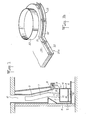
- soot which clings along the vertical walls of the flue pipe of the chimney. Due to variations in pressure and temperature, soot is permanently detached from this duct and is therefore, by gravity, caused to fall into the hood and downstream.
- the invention aims to solve the above problems by proposing a new heat recovery device able to be inserted into the open hearth of a chimney, while offering the user easy and rapid access to the upper part of the 'insert in place, to the connection nozzle with the smoke evacuation pipe, as well as to the buffer or to the plate.
- the invention also aims to offer the same accessibility possibilities for an insert of simple structure or, indifferently, an insert of the type with peripheral ventilation comprising, for this purpose, a jacket enveloping it on at least four faces, the above.
- the heat recovery device is characterized in that the top wall consists of: - a rear half-plate extending perpendicular to the bottom wall, fixed on the latter and on the side walls, comprising a semi-circular median extension extending beyond the longitudinal edge directed towards the front frame and having, in its middle part and in the extension, a hole bordered by a connection nozzle rising from the upper face of the rear half-plate, a front half-plate having, in its middle part and from the longitudinal edge oriented in the direction of the bottom wall, a nesting notch complementary to the extension, said half-plate comprising removable fixing means on at least the side walls.
- Fig. 1 illustrates the problem that the invention aims to solve, in the case of a chimney 1 whose open hearth 2 is equipped with a heat recovery device 3 .
- a heat recovery device 3 In known manner, such an apparatus 3 is inserted into the hearth 2 to rest on the hearth 4 while being located at a distance from the counter-core 5 and the straight feet 6 .
- the recovery device 3 is used in combination with a casing 7 intended to conduct the flue gases and combustion gases through a drain 8 , a hood 9 and a flue pipe 10 from the chimney 1 .
- the device 3 comprises a top 11 delimiting an orifice 12 bordered by a nozzle 13 on which fits the lower end portion of the casing 7.
- a device 3 has a front door 14 d access to the internal combustion volume which is separated from an underlying exchange volume 15 by a bottom 16 forming a hearth.
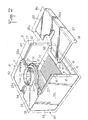
- the invention proposes make a heat recovery device 3 , as shown in figs. 2 and 3 .
- Fig. 2 shows, more particularly in exploded view, that the heat recovery device 3 comprises, as said previously, an exchange box 15 whose wall 16 constitutes the combustion hearth of a superimposed combustion box 18 .
- the hearth 16 is associated with a grid 20 composed of exchange tubes 21 able to promote a circulation of heated air recycled in the room.
- the object of the invention does not relate to the exchange means which are neither shown nor more precisely described in the following.
- the combustion box 18 is delimited by two side walls 23 , by a bottom wall 24 , by a front frame, not shown, capable of supporting the door 14 and from above 11 .
- the top 11 is constituted by a half-plate 25 , called rear, fixed by suitable adaptation members 26 , both on the corresponding parts of the upper edges of the side walls 23 and on the upper edge of the bottom wall 24 .
- the edges of the walls 23 and 24 can be provided with a molding 27 intended to cooperate with a sealing bead housed in a complementary groove or groove presented by the underside of the half-plate 25 .
- the mounting of the half-plate 25 is carried out so that the longitudinal edge 25 a of the latter is preferably located in the extension of the corresponding face of the bottom plate 24 .
- the second longitudinal edge 25b of the half-plate 25 has, in its central region and projecting an extension 28 of the type substantially semicircular.
- the half-plate 25 has a circular orifice 29 which is also formed in the extension 28 and in the half-plate 25 .
- the orifice 29 is bordered by a nozzle 30 , removable or not, rising from the upper face of the half-plate 25 to a height conventional in the technical field considered, to ensure nesting and functional connection suitable with the corresponding end part casing 7 .
- the half-plate 25 therefore has a width substantially equal to the corresponding half-measure of the top 11 , in particular when it is desired to arrange the nozzle 30 along a vertical median plane parallel to the front of the recovery device.
- Figs. 2 and 3 show that, according to a feature of the invention, the longitudinal edge 25b of the half-plate 25 and the edge of the extension 28 have a continuous rabbet 31 formed from the upper face of the half-plate 25 to a depth corresponding to the mid-thickness.
- the rebate 31 thus defines a range 32 offset below relative to the upper face of the half-plate 25 .
- Such a range 32 preferably has a groove 33 for the establishment of a sealing bead of any suitable material capable of withstanding the temperature constraints prevailing locally during the operation of the recovery device.
- the top 11 also comprises a second half-plate 35 , called the front, whose surface is complementary to the rear half-plate 25 so that, in association, they together form the top 11 .
- the underside of the half-plate 35 includes, set back from the two transverse edges, sealing beads intended to cooperate with the moldings 27 .
- the front half-plate 35 can be fixed to the edges of the two side walls 23 by fastening members 36 , of the type used for the half-plate 25 and passing through a dropped edge 37 extending the longitudinal front edge 35 a .
- a flange 37 is also provided to assume a function of bracing lintel between the side walls 23 to secure the latter and facilitate, if necessary, the mounting of the front frame not shown in the drawings.
- the front half-plate 35 delimits, in its longitudinal edge 35 b facing the half-plate 25 , a notch 38 formed in the middle part, according to a conformation complementary to that of the extension 28 .
- the longitudinal edge 35 b delimit a rebate 41 complementary to the rebate 31 , so as to allow mutual interlocking during the positioning of the half-plate 35 .
- the rebate 41 is therefore produced in a reverse manner to the rebate 31 , so that the flat area 42 is able to cooperate with the flat area 32 .
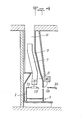
- the constitution of the heat recovery device makes it possible to carry out a conventional insertion into the open hearth 2 , as illustrated in FIG. 4 , after engagement of the casing 7 through the drain 8 , the hood 9 and the duct 10 .
- the absence of the front half-plate 35 combined with an opening or a dismantling of the door 14 , provides wide access to the drain 8 and offers a visual perception of appreciation not hindered.
- the installer can thus carry out in the best conditions the operations of fitting the casing 7 onto the nozzle and of adjusting the draw valve 17 .
- the front half-plate 35 can be put in place by sliding from the positions illustrated in FIGS. 2 and 4 , until the complementary interlocking of the rebates 31 and 41 is ensured.
- This interlocking is obtained with certainty when the upper edges of the side walls 23 form the moldings 27 which then assume a function of guide rail and sliding.
- the final fixing then takes place by the installation of the fixing members 36 passing through the lintel 37 to cooperate with counterparts 40 carried by the front edges of the side walls 23 .
- the final constitution of the heat recovery device can then be completed by fitting the front frame and the door 14 .
- the means implemented by the object of the invention therefore allow easy and safe mounting of the elements constituting the device, as well as a possibility of rapid disassembly of the front half-plate 35 when it is necessary to access the volume of the drain 8 for, in particular: - carry out cleaning, - adjust, dismantle or maintain the draft shutter 17 , - change the casing 7 .
- a recovery device 3 can be provided with an outer lining jacket 50 extending away from the top 11 , the bottom plate 24 and the side walls 23 .
- the function of such a jacket 50 is to regulate the operating temperature and to allow secondary circulation taking up the calories absorbed by the walls of the device.
- the invention recommends making the jacket 50 in such a way that it comprises, as a top 51 , only a half panel 52 integral with the sides 53 and covering the half-plate 25 .
- the top 51 is completed by a half-panel 54 corresponding to the half-plate 35 and, preferably, carried by the latter.
- the half-plate 35 and the half-panel 54 make it possible to obtain, simultaneously, the reconstruction of the tops 11 and 51 or to clear the access to the drain 8 .
Landscapes
- Engineering & Computer Science (AREA)
- Chemical & Material Sciences (AREA)
- Combustion & Propulsion (AREA)
- Mechanical Engineering (AREA)
- General Engineering & Computer Science (AREA)
- Housings, Intake/Discharge, And Installation Of Fluid Heaters (AREA)
Applications Claiming Priority (2)
| Application Number | Priority Date | Filing Date | Title |
|---|---|---|---|
| FR8602059 | 1986-02-12 | ||
| FR8602059A FR2594214B1 (fr) | 1986-02-12 | 1986-02-12 | Appareil recuperateur de chaleur pour cheminee a foyer ouvert |
Publications (1)
| Publication Number | Publication Date |
|---|---|
| EP0236244A1 true EP0236244A1 (de) | 1987-09-09 |
Family
ID=9332155
Family Applications (1)
| Application Number | Title | Priority Date | Filing Date |
|---|---|---|---|
| EP87420042A Withdrawn EP0236244A1 (de) | 1986-02-12 | 1987-02-11 | Wärmerekuperator für offene Kamine |
Country Status (2)
| Country | Link |
|---|---|
| EP (1) | EP0236244A1 (de) |
| FR (1) | FR2594214B1 (de) |
Cited By (1)
| Publication number | Priority date | Publication date | Assignee | Title |
|---|---|---|---|---|
| GB2247075A (en) * | 1990-07-20 | 1992-02-19 | Northern Chimney Linings Syste | Sealing device between gas fire and flue |
Families Citing this family (1)
| Publication number | Priority date | Publication date | Assignee | Title |
|---|---|---|---|---|
| FR2788840B1 (fr) | 1999-01-22 | 2001-04-27 | Lacanche Soc Ind De | Bruleur a gaz pour appareil de cuisson |
Citations (2)
| Publication number | Priority date | Publication date | Assignee | Title |
|---|---|---|---|---|
| DE2339215A1 (de) * | 1973-08-02 | 1975-02-13 | Everken Olsberger Huette Kg | Kamineinsatz |
| EP0142452A1 (de) * | 1983-08-25 | 1985-05-22 | Societe Industrielle Deville-S.A. | Deckel für Kochherde oder für Heizeinrichtungen |
-
1986
- 1986-02-12 FR FR8602059A patent/FR2594214B1/fr not_active Expired
-
1987
- 1987-02-11 EP EP87420042A patent/EP0236244A1/de not_active Withdrawn
Patent Citations (2)
| Publication number | Priority date | Publication date | Assignee | Title |
|---|---|---|---|---|
| DE2339215A1 (de) * | 1973-08-02 | 1975-02-13 | Everken Olsberger Huette Kg | Kamineinsatz |
| EP0142452A1 (de) * | 1983-08-25 | 1985-05-22 | Societe Industrielle Deville-S.A. | Deckel für Kochherde oder für Heizeinrichtungen |
Cited By (1)
| Publication number | Priority date | Publication date | Assignee | Title |
|---|---|---|---|---|
| GB2247075A (en) * | 1990-07-20 | 1992-02-19 | Northern Chimney Linings Syste | Sealing device between gas fire and flue |
Also Published As
| Publication number | Publication date |
|---|---|
| FR2594214B1 (fr) | 1988-06-03 |
| FR2594214A1 (fr) | 1987-08-14 |
Similar Documents
| Publication | Publication Date | Title |
|---|---|---|
| US3952721A (en) | Stove with cooking plate | |
| CA1167724A (fr) | Capteur de chaleur pouvant etre installe notamment dans une cheminee domestique et procede pour porter a une temperature plus elevee un fluide tel que de l'eau | |
| FR2550611A1 (fr) | Foyer pour cheminee mixte destine a fonctionner ouvert et ferme | |
| CA2858467A1 (fr) | Appareil de chauffage a tres haut rendement, de tres faible profondeur et a vision etendue | |
| EP0236244A1 (de) | Wärmerekuperator für offene Kamine | |
| EP0094455A2 (de) | Rost für die Verbrennung von festen Brennstoffen in häuslichen Öfen, Industrieöfen, Herden usw. | |
| FR2529646A2 (fr) | Appareil de chauffage a bois encastrable a foyer apparent | |
| CA1130682A (fr) | Cheminee a feu de bois prefabriquee a haut rendement calorifique | |
| FR2558573A1 (fr) | Procede de combustion applicable aux chambres de combustion de foyers fermes, chaudieres a combustible solide et similaires | |
| EP0102911A2 (de) | Einrichtung und Verfahren zur Wärmerekuperation für einen Feuerraum | |
| FR2527315A1 (fr) | Appareil de combustion a double foyer pour combustibles solides | |
| FR2502304A1 (fr) | Recuperateur de chaleur pour cheminee d'habitation | |
| FR2555712A1 (fr) | Foyer ferme perfectionne pour cheminees a feu ouvert | |
| FR2597197A1 (fr) | Recipient de combustion du type cheminee | |
| FR2588942A1 (fr) | Foyer universel pour combustibles solides | |
| FR2726073A1 (fr) | Dispositif et procede de distribution d'air de combustion dans des installations de chauffage, notamment a combustibles solides | |
| EP0106832A2 (de) | Heizeinrichtung umwandelbar in eine Einrichtung mit geschlossener oder offener Feuerung | |
| FR2777982A1 (fr) | Dispositif de cheminee a insert a gaz | |
| EP0193433A1 (de) | Heizungsanlage für offene Kamine mit umgekehrtem Zug | |
| FR2506902A1 (fr) | Cheminee-poele monobloc a circulation d'air et a parachevement catalytique de la combustion | |
| EP0271392A1 (de) | Feststoffbefeuerter Heizkessel und insbesondere Holzbefeuerter Heizkessel | |
| BE411895A (de) | ||
| FR2885993A1 (fr) | Appareil a foyer ouvert recuperateur de chaleur pour l'equipement des cheminees d'appartement. | |
| FR2595135A1 (fr) | Foyer de cheminee a feux de bois pouvant fonctionner soit en " foyer ouvert " soit en " foyer ferme " | |
| FR2518224A1 (fr) | Dispositif de recuperation de calories associe a une cheminee a feu ouvert et a tirage renverse |
Legal Events
| Date | Code | Title | Description |
|---|---|---|---|
| PUAI | Public reference made under article 153(3) epc to a published international application that has entered the european phase |
Free format text: ORIGINAL CODE: 0009012 |
|
| AK | Designated contracting states |
Kind code of ref document: A1 Designated state(s): BE CH DE GB LI LU SE |
|
| 17P | Request for examination filed |
Effective date: 19880303 |
|
| 17Q | First examination report despatched |
Effective date: 19890120 |
|
| STAA | Information on the status of an ep patent application or granted ep patent |
Free format text: STATUS: THE APPLICATION IS DEEMED TO BE WITHDRAWN |
|
| 18D | Application deemed to be withdrawn |
Effective date: 19900918 |