EP0236409B1 - Plan porteur - Google Patents
Plan porteur Download PDFInfo
- Publication number
- EP0236409B1 EP0236409B1 EP86905357A EP86905357A EP0236409B1 EP 0236409 B1 EP0236409 B1 EP 0236409B1 EP 86905357 A EP86905357 A EP 86905357A EP 86905357 A EP86905357 A EP 86905357A EP 0236409 B1 EP0236409 B1 EP 0236409B1
- Authority
- EP
- European Patent Office
- Prior art keywords
- hydrofoil
- angle
- tip
- foil
- length
- Prior art date
- Legal status (The legal status is an assumption and is not a legal conclusion. Google has not performed a legal analysis and makes no representation as to the accuracy of the status listed.)
- Expired - Lifetime
Links
- 239000011888 foil Substances 0.000 title claims abstract description 75
- 239000000463 material Substances 0.000 claims abstract description 8
- 239000007788 liquid Substances 0.000 claims description 5
- 238000005728 strengthening Methods 0.000 claims description 5
- 230000001965 increasing effect Effects 0.000 claims description 4
- 230000000750 progressive effect Effects 0.000 claims description 3
- 150000001875 compounds Chemical class 0.000 claims 1
- 230000006835 compression Effects 0.000 claims 1
- 238000007906 compression Methods 0.000 claims 1
- 239000000835 fiber Substances 0.000 claims 1
- 238000005452 bending Methods 0.000 abstract description 4
- 230000002708 enhancing effect Effects 0.000 abstract description 4
- 238000013461 design Methods 0.000 description 15
- 230000008901 benefit Effects 0.000 description 9
- 238000009826 distribution Methods 0.000 description 7
- 230000000694 effects Effects 0.000 description 6
- 230000007423 decrease Effects 0.000 description 5
- 230000003247 decreasing effect Effects 0.000 description 5
- 238000000034 method Methods 0.000 description 5
- 239000012530 fluid Substances 0.000 description 4
- 238000011161 development Methods 0.000 description 3
- 230000009467 reduction Effects 0.000 description 3
- 238000000926 separation method Methods 0.000 description 3
- 230000001154 acute effect Effects 0.000 description 2
- 230000006872 improvement Effects 0.000 description 2
- 230000003993 interaction Effects 0.000 description 2
- 239000007787 solid Substances 0.000 description 2
- 230000002730 additional effect Effects 0.000 description 1
- 238000013459 approach Methods 0.000 description 1
- 239000002131 composite material Substances 0.000 description 1
- 230000001419 dependent effect Effects 0.000 description 1
- 230000002349 favourable effect Effects 0.000 description 1
- 238000012417 linear regression Methods 0.000 description 1
- 230000004048 modification Effects 0.000 description 1
- 238000012986 modification Methods 0.000 description 1
- 230000002787 reinforcement Effects 0.000 description 1
- 230000004044 response Effects 0.000 description 1
- 230000009291 secondary effect Effects 0.000 description 1
- 230000003019 stabilising effect Effects 0.000 description 1
- 239000003381 stabilizer Substances 0.000 description 1
- 230000003068 static effect Effects 0.000 description 1
- XLYOFNOQVPJJNP-UHFFFAOYSA-N water Substances O XLYOFNOQVPJJNP-UHFFFAOYSA-N 0.000 description 1
Images


Classifications
-
- B—PERFORMING OPERATIONS; TRANSPORTING
- B63—SHIPS OR OTHER WATERBORNE VESSELS; RELATED EQUIPMENT
- B63B—SHIPS OR OTHER WATERBORNE VESSELS; EQUIPMENT FOR SHIPPING
- B63B1/00—Hydrodynamic or hydrostatic features of hulls or of hydrofoils
- B63B1/16—Hydrodynamic or hydrostatic features of hulls or of hydrofoils deriving additional lift from hydrodynamic forces
-
- B—PERFORMING OPERATIONS; TRANSPORTING
- B63—SHIPS OR OTHER WATERBORNE VESSELS; RELATED EQUIPMENT
- B63B—SHIPS OR OTHER WATERBORNE VESSELS; EQUIPMENT FOR SHIPPING
- B63B39/00—Equipment to decrease pitch, roll, or like unwanted vessel movements; Apparatus for indicating vessel attitude
- B63B39/06—Equipment to decrease pitch, roll, or like unwanted vessel movements; Apparatus for indicating vessel attitude to decrease vessel movements by using foils acting on ambient water
-
- B—PERFORMING OPERATIONS; TRANSPORTING
- B63—SHIPS OR OTHER WATERBORNE VESSELS; RELATED EQUIPMENT
- B63B—SHIPS OR OTHER WATERBORNE VESSELS; EQUIPMENT FOR SHIPPING
- B63B41/00—Drop keels, e.g. centre boards or side boards ; Collapsible keels, or the like, e.g. telescopically; Longitudinally split hinged keels
-
- B—PERFORMING OPERATIONS; TRANSPORTING
- B64—AIRCRAFT; AVIATION; COSMONAUTICS
- B64C—AEROPLANES; HELICOPTERS
- B64C3/00—Wings
- B64C3/10—Shape of wings
-
- B—PERFORMING OPERATIONS; TRANSPORTING
- B63—SHIPS OR OTHER WATERBORNE VESSELS; RELATED EQUIPMENT
- B63B—SHIPS OR OTHER WATERBORNE VESSELS; EQUIPMENT FOR SHIPPING
- B63B35/00—Vessels or similar floating structures specially adapted for specific purposes and not otherwise provided for
- B63B2035/009—Wind propelled vessels comprising arrangements, installations or devices specially adapted therefor, other than wind propulsion arrangements, installations, or devices, such as sails, running rigging, or the like, and other than sailboards or the like or related equipment
-
- Y—GENERAL TAGGING OF NEW TECHNOLOGICAL DEVELOPMENTS; GENERAL TAGGING OF CROSS-SECTIONAL TECHNOLOGIES SPANNING OVER SEVERAL SECTIONS OF THE IPC; TECHNICAL SUBJECTS COVERED BY FORMER USPC CROSS-REFERENCE ART COLLECTIONS [XRACs] AND DIGESTS
- Y02—TECHNOLOGIES OR APPLICATIONS FOR MITIGATION OR ADAPTATION AGAINST CLIMATE CHANGE
- Y02T—CLIMATE CHANGE MITIGATION TECHNOLOGIES RELATED TO TRANSPORTATION
- Y02T50/00—Aeronautics or air transport
- Y02T50/10—Drag reduction
Definitions
- the present invention relates to a foil, and particularly, but not exclusively to families of hydrofoils and aerofoils characterised by high efficiency which are forward raked.
- a hydrofoil having a forward swept leading edge was described for instance in GB 2930 (A.D. 1860).
- a hydrofoil includes several features which are defined below to assist in the understanding of the specification.
- a hydrofoil is defined as any solid body or part thereof, that is fixed or rotating in relation to any other body, for which there exists such an orientation of the hydrofoil in relation to a non-zero undisturbed flow velocity V ⁇ , that the circulation r of the velocity field along a closed directed curve K drawn around the hydrofoil is not equal to zero. This is depicted in Fig. 1 of the drawings.
- hydrofoils and aerofoils are : fins, wings, propeller blades, pump impeller blades, turbine vane and rotor blades, stabilising fins, hydrofoil wings, rudders, keels, flettner rotors, centreboards, daggerboards, sideboards, skegs, entire underwater parts of hulls of most ships etc.
- a hydrofoil base is a section or an end of the hydrofoil, which is either fixed to another body or where the continuation of the same body changes considerably its hydrofoil properties in a way that its local section value of the ratio C L /C D is reduced or vanishes, or where the fluid medium discontinues because of a solid or free surface, or alternatively the base of a hydrofoil is its section by a plane of symmetry of the hydrofoil.
- Examples of hydrofoil bases are : a connection of a fin to a structure, a section of a hydrofoil wing where it protrudes from water to air, a plane of symmetry of a wing shaped submersible vessel etc.
- the hydrofoil tip is defined as an end part of the hydrofoil which is not its base and the hydrofoil main line is defined as the geometrical locus of the centre of efforts of hydrofoil sections by families of planes or cylinders which section the foil surface in such a way that each plane or cylinder surface passes through one point of the leading edge and one of the trailing edge.
- the hydrofoil main line lies on the surface created by all the section mean lines of the hydrofoil.
- the sectioning surface (planes or cylinders or other rotational surfaces if they are more appropriate) should be approximately in line with the streamlines around the hydrofoil. These streamlines should start in the region of the leading edge and pass around both the pressure and the suction sides of the hydrofoil.
- the hydrofoil plan plane is determined by minimising the squares of distances of points of both surfaces of the hydrofoil (multiple linear regression). In case the hydrofoil suction and pressure surfaces are identical it is the hydrofoil plane of symmetry, otherwise it shall be determined by using the coordinates of 40 points evenly distributed on both pressure and suction surfaces of the hydrofoil (20 on each side).
- the orthogonal projection of the surface of the hydrofoil on the plan plane shall be called the hydrofoil plan.
- the hydrofoil chord surface is defined as the surface which is formed by the hydrofoil chords. Each of the chord lines shall be that of individual above-defined sections.
- the hydrofoil perpendicular is determined for individual points of the hydrofoil chord surface. It is the direction of a straight line which is tangent to the chord surface and perpendicular to the undisturbed flow velocity V ⁇ in the given point of the chord surface.
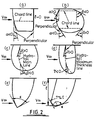
- Angle ⁇ measured, at each point along the leading edge is defined as the angle between the hydrofoil perpendicular and the tangent to the leading edge (Figs. 2a, b). Angle ⁇ is measured between the directions on the leading edge and the hydrofoil perpendicular, both towards the tip or both towards the hydrofoil base. Angle ⁇ has the opposite sign to that of the cosine of the angle measured between the direction of V ⁇ and the tipwards direction on the tangent to the leading edge.
- Angle ⁇ (seen in Fig. 2c) is determined in the same way as angle ⁇ , with the leading edge replaced by main line.
- Angle y (seen in Fig. 2d) is determined in the same way as angles ⁇ and p, and shall be measured to the tangent of the maximum thickness line.
- Angle 8 (Fig. 2a, b) is measured in the same way as angles ⁇ , p and y above to the direction of the trailing edge.
- Angle E is defined as the absolute value of the difference of angles ⁇ and ⁇ .
- a sharp ended hydrofoil as shown in Fig. 2e, it is measured at the hydrofoil tip.
- angle s is measured between the tangents at points that are 7 % of t distant from the point on the hydrofoil tip which is furthermost from the hydrofoil base.
- An induced vortex is the result of three dimensional flow from the pressure side to the suction side of the hydrofoil around the foil tip.
- the streamlines in the induced flow are usually at a large angle relating to V co and are considerably curved.
- V co the suction side of the hydrofoil around the foil tip.
- a typical hydrofoil vorticity increases along the tip edge as more and more streamlines combine together. This is further enhanced by the development of the boundary layer, the thickness of which increases along the chord.
- the flow in the boundary layer decelerates and smaller pressure gradients are sufficient to cause movement of relatively bigger masses of the liquid from the places of high pressures to those with lower pressures, in particular around the hydrofoil tip.
- This cross motion further increases the effective thickness of the boundary layer in the tip region and develops a large scale separation zone, which is accompanied by locally high viscous drag.
- the best known method to improve hydrofoil efficiency (defined as the ratio C L /C D ) is to increase the aspect ratio which simultaneously increases the lift co-efficient and reduces the drag co-efficient.
- this method has many limitations.
- a limited forward inclining of hydrofoils (less than 10') is sometimes used by dinghy sailors.
- One reason for putting the centreboard in the 5' to 10' forward swept position is to give more control over the position of lateral resistance of a boat under some special wind force and sailing conditions, thus obtaining a better equilibrium of the boat, which, in turn, decreases undesirable forces on the rudder.
- Another reason is to effect a tighter turn during gybing. This, however, is rarely performed with the foil in a fully forward inclined position. The tighter turn is possible due to lift force on the centreboard during turning, which can be enhanced by torsion of the foil.
- An object of the present invention is to provide an improved hydrofoil which obviates or mitigates the aforesaid disadvantages.
- the longitudinal component of velocity is introduced in the tip region or along the major part of the foil. This modifies the flow in the tip region so that some of the streamlines that would otherwise have been directed around the tip from the pressure side to the suction side of the hydrofoil are instead deflected towards a more streamlined flow around the profile.
- An increase in local velocity near to the tip due to the longitudinal component of the flow is associated with a greater shear in the flow and the decrease in the thickness of the boundary layer.
- Laminar flow can exist over a larger proportion of the hydrofoil area near to the tip, the size of turbulent separation is reduced and the induced vortex smaller. Lift on the hydrofoil is higher and the induced drag lower than on efficient designs not having these features.
- the part of viscous drag which is related to the shedding of the induced vortex is also decreased.
- the areas of the highest pressure differences can be even better separated. This is achieved by inclining the maximum thickness line more towards the flow than the leading edge primarily in the region of the tip.
- the lengthwise distributions of angles ⁇ , p, y and ⁇ farther from the hydrofoil tip are also of importance, because the desired effects can be better attained with the flow that is as close to a streamline flow as possible.
- foil length can also be used, the choice being dependent on the particular flow conditions in the tip region, along the whole hydrofoil and also flow interaction with other foils and or bodies, as for example the interaction of a ship stabiliser fin boundary layer or/and cavitation path with the ship hull or/and boundary layer of the ship hull or/and the ship propeller.
- Many hydrodynamic, aerodynamic design criteria should be taken into account as the foil efficiency, strength, flutter, vibration, generation of noise, mixing efficiency in a mixing vessel etc.
- the general direction would be to choose higher percentages of the foil length l in order to determine the foil tip area which is desired to be raked forward, or to clarify the scope of this description, for foils which have low aspect ratios, while the smaller percentages of t would be appropriate for foils of higher aspect ratios.
- the above listed values of 50 %, 30 % and 10 % of f are not the only possible ones, the intermediate values can be also chosen depending on relevant criteria as those, which were for example mentioned above. In cases of very low aspect ratio, even up to 100 % of the foil length l i.e. the whole body of the foil would be qualified as a tip area.
- geometrical aspect ratios smaller than one as considerable improvement of the flow and/or other important flow related features may be, in some flow situations, obtained with the whole body of the foil swept towards the flow. In such a case it would be most appropriate to qualify 100 % of l as the tip area.
- the above value of geometrical aspect ratio of one is an indication only, and in a case similar flow situation is attained with a lower (or higher) value of aspect ratio, such a lower value (or higher value) should be used to determine the extent of the tip area.
- a more regular flow leaves the designer more freedom as to what to regard as the foil tip area.
- One of the families of the invented shapes of hydrofoils is characterised by the reduction of the high drag and low lift vortex enhancing area near to the tip. This is performed by gradually decreasing the chord length towards the hydrofoil tip, so that hydrofoil tip has a lower plan radius or is pointed. This has the advantages of reducing the length over which the induced vortex would develop as well as reducing the wetted area of the region where the boundary layer would be thickest and viscous drag most significant. These effects are further enhanced by the higher shear and more streamline flow in the region of the tip, as well as the gradual decrease of the pressure difference between the suction and the pressure sides, which accompany the gradual decrease of the chord length towards the foil tip. The proximity of the trailing edge which forms a larger angle with the undisturbed flow can facilitate some merging of the induced vortex with the trailing vortices which tend to be smaller and dissipate faster.
- Angle ⁇ can be used as a measure of reduction of the undesirable vortex enhancing area near to the tip and a broad indication can be given that angle s should best be smaller than or equal to 80'.
- angle s should best be smaller than or equal to 80'.
- ⁇ t is the value of angle ⁇ at the point of the leading edge used to determine angle E .
- angle ⁇ smaller than 60° or even 45° or angles s smaller than 80' - at, 60' - ⁇ t or even 45' - ⁇ t .
- Other numeric values could also be used above, both between 45' and 89° as well as below 45', as the above used values are examples only, quoted to signal the order of magnitude of preferred values of angle s.
- a foil plan shape which is near to elliptical is known, also for unswept foils and for swept backward foils to give high lift and low drag foil characteristics.
- the nature of this invention is in particular to use forward rake for shapes which have similar to elliptical plan shapes of the foil.
- Elliptical or near to elliptical, foil shape while combined with forward rake has the advantages of reduced undesirable vortex-enhancing area near to the foil tip, while the lengthwise trailing vortices distribution is close to optimal.
- plan shapes with straight or nearly straight leading edge over the whole foil length or only in the tip region and the shape of the trailing edge resulting from elliptical or near to elliptical chord distribution offer these advantages (Fig. 2f & Fig. 5).
- the plan shape of the foil can, in some cases, be defined by introducing limits on the radius of curvature of the leading and trailing edges.
- a radius of curvature of an elliptical plan shape which has been proved to possess very good flow properties over a high range of aspect ratios while combined with forward rake, can be used to mark restrictions on the preferred plan shapes.
- the value of this radius of curvature can be corrected with an arbitary coefficient in order to allow for those plan shapes, which are not strictly elliptical and which possess good flow properties.
- the values of such arbitary coefficients can be chosen as 1.2, 1.5, 2.0 or 5.0 for most foil shapes.
- Another measure of the size of the vortex enhancing area near to the tip apart from angle E can be the chord/length at the foil tip. Good glow properties can be attained with the tip chord length not greater than 60 % of the maximum chord length of the foil, or better if the tip chord length is smaller than 40 %, 30 % or even 20 % of the maximum chord length of the foil.
- Figs. 4a to 4f of the drawings depict hydrofoils according to the invention and which are characterised by the forward inclination of the entire or a major part of the leading edge.
- the inclination of the leading edge creates a longitudinal flow along the edge. This prevents stagnation and reduces the thickness of the boundary layer, thus decreasing viscous drag.
- An additional effect is that, because of the above, laminar flow can be maintained over a larger area, thus for some applications the maximum thickness line can be moved towards the trailing edge. Longitudinal flow separation at higher angles of attack is less likely and the leading edge section radius can be modified accordingly. This can result in a flatter C c /C L characteristic over a range of angles of attack and lower values of drag coefficient.
- hydrofoils In the case of a propeller, pump, impeller or turbine rotor or vane, blades, where centrifugal and Coriolis forces occur, the hydrofoils have further advantages.
- angles ⁇ of the order of 50' to 65' but with favourable chord length distribution in the tip region ⁇ values of 66' to 75° can give very good results.
- angles ⁇ and y should be increased depending on the centrifugal force effect on the flow.
- a forward inclined portion of a hydrofoil can, however, be subjected to significant torsion combined with bending and has different flutter characteristics than those of commonly used designs.
- This is best illustrated in Fig. 5 which shows a hydrofoil which has been strengthened by applying high directional strength materials in the direction that is inclined at an acute angle, in general varying, to the main line.
- This material, or these materials when more than one set of directional strength provisions are chosen are used in addition to reinforcements which have more isotropic two dimensional mechanical properties or which have higher stiffness in the longitudinal or/and transverse directions on the foil.
- the hereby described technique increases combined torsional and bending stiffness as well as producing a special antistalling effect.
- FIG. 5 illustrates an example only and the hereby described invented method of strengthening hydrofoils can be used with high modulus materials arranged in a few directions over a certain range of the acute angles as described above. Particular arrangements depend on applications and a wide range of static mechanical properties and dynamic response characteristics can be attained by a suitable combination of materials and their arrangement, in particular for composite materials.
Landscapes
- Engineering & Computer Science (AREA)
- Mechanical Engineering (AREA)
- Chemical & Material Sciences (AREA)
- Combustion & Propulsion (AREA)
- Ocean & Marine Engineering (AREA)
- Physics & Mathematics (AREA)
- Fluid Mechanics (AREA)
- Aviation & Aerospace Engineering (AREA)
- Structures Of Non-Positive Displacement Pumps (AREA)
Abstract
Claims (16)
Applications Claiming Priority (2)
| Application Number | Priority Date | Filing Date | Title |
|---|---|---|---|
| GB8522270 | 1985-09-09 | ||
| GB858522270A GB8522270D0 (en) | 1985-09-09 | 1985-09-09 | Velocity hydrofoils |
Publications (2)
| Publication Number | Publication Date |
|---|---|
| EP0236409A1 EP0236409A1 (fr) | 1987-09-16 |
| EP0236409B1 true EP0236409B1 (fr) | 1990-03-28 |
Family
ID=10584904
Family Applications (1)
| Application Number | Title | Priority Date | Filing Date |
|---|---|---|---|
| EP86905357A Expired - Lifetime EP0236409B1 (fr) | 1985-09-09 | 1986-09-09 | Plan porteur |
Country Status (5)
| Country | Link |
|---|---|
| US (1) | US4949919A (fr) |
| EP (1) | EP0236409B1 (fr) |
| DE (1) | DE3669851D1 (fr) |
| GB (1) | GB8522270D0 (fr) |
| WO (1) | WO1987001345A1 (fr) |
Cited By (1)
| Publication number | Priority date | Publication date | Assignee | Title |
|---|---|---|---|---|
| WO2019195153A1 (fr) * | 2018-04-02 | 2019-10-10 | Aero Design Labs, Inc. | Extrémité d'aile elliptique et son procédé de fabrication |
Families Citing this family (35)
| Publication number | Priority date | Publication date | Assignee | Title |
|---|---|---|---|---|
| US4940438A (en) * | 1989-05-12 | 1990-07-10 | Miller S Scott | Surfboard with angularly related fins |
| US5136961A (en) * | 1989-12-21 | 1992-08-11 | Follett Harold E | Hydroplaning hydrofoil/airfoil structures and amphibious and aquatic craft |
| GB9105767D0 (en) * | 1991-03-19 | 1991-11-06 | British Aerospace | Wing root design of forward swept wings |
| DE4211257A1 (de) * | 1991-08-19 | 1993-02-25 | F2 Int Gmbh | Finne fuer ein segelsurfbrett |
| US5653189A (en) * | 1991-12-20 | 1997-08-05 | Dynafoils, Inc. | Hydrofoil craft |
| US5311832A (en) * | 1991-12-20 | 1994-05-17 | Dynafoils, Inc. | Advanced marine vehicles for operation at high speeds in or above rough water |
| JPH07506318A (ja) * | 1992-04-28 | 1995-07-13 | ブリティッシュ テクノロジイ グループ ユーエスエー,インク. | 後流うずの強さを減じた揚力物体 |
| US5309859A (en) * | 1993-04-13 | 1994-05-10 | Miller Richard T | Hydrofoil device |
| US5634613A (en) * | 1994-07-18 | 1997-06-03 | Mccarthy; Peter T. | Tip vortex generation technology for creating a lift enhancing and drag reducing upwash effect |
| DE9418686U1 (de) * | 1994-11-22 | 1995-01-26 | TZ Technisches Zentrum Entwicklungs- & Handelsgesellschaft mbH, 04109 Leipzig | Finne insbesondere für Surfbretter |
| DE10116087A1 (de) * | 2001-03-30 | 2002-10-10 | Sms Demag Ag | Verstellbarer Kokillenteiler zum Einbau in eine konventionelle Brammenkokille |
| DE10117721B4 (de) * | 2001-04-09 | 2007-09-27 | Gerd Heller | Flügelspitzenverlängerung für einen Flügel |
| US7207526B2 (en) * | 2002-06-26 | 2007-04-24 | Mccarthy Peter T | High efficiency tip vortex reversal and induced drag reduction |
| AU2003249321B2 (en) * | 2002-07-19 | 2010-02-18 | Peter T. Mccarthy | Propulsion hydrofoils |
| US7108572B1 (en) | 2003-10-20 | 2006-09-19 | Bennett Ronald D | Sailboard with multiple skegs |
| US7436882B2 (en) * | 2003-12-19 | 2008-10-14 | Broadcom Corporation | Decision feedback equalizer and clock and data recovery circuit for high speed applications |
| US7100867B2 (en) * | 2004-02-09 | 2006-09-05 | Houck Ii Ronald G | Lifting foil |
| USD516994S1 (en) | 2004-02-09 | 2006-03-14 | Houck Ii Ronald G | Lifting foil |
| RU2270128C1 (ru) * | 2004-08-13 | 2006-02-20 | Общество С Ограниченной Ответственностью "Мидера-К" | Гидродинамическое крыло (варианты) |
| US7644892B1 (en) | 2006-07-06 | 2010-01-12 | Alford Jr Lionel D | Blended winglet |
| US20090258553A1 (en) * | 2008-04-15 | 2009-10-15 | Derek Robert Leek | Thick, elliptical-planform fin for a water sports board |
| US9302766B2 (en) | 2008-06-20 | 2016-04-05 | Aviation Partners, Inc. | Split blended winglet |
| ES3040742T3 (en) * | 2008-06-20 | 2025-11-04 | Aviation Partners Inc | Curved wing tip |
| US20100000461A1 (en) * | 2008-07-07 | 2010-01-07 | Waite Arthur G | Foil shapes for use in barge skegs and marine propeller shrouds |
| US8926385B1 (en) | 2009-11-02 | 2015-01-06 | David Woods | High efficiency swim fin using multiple high aspect ratio hydrodynamic vanes with pliable hinges and rotation limiters |
| AU2011256124A1 (en) * | 2010-05-17 | 2013-01-10 | Fin Control Systems Pty. Limited | A fin for surf craft |
| GB201011843D0 (en) * | 2010-07-14 | 2010-09-01 | Airbus Operations Ltd | Wing tip device |
| DK3650337T3 (da) | 2011-06-09 | 2021-02-22 | Aviation Partners Inc | Delt "blended" winglet |
| US10562613B2 (en) * | 2013-12-04 | 2020-02-18 | Tamarack Aerospace Group, Inc. | Adjustable lift modification wingtip |
| DE102015103021A1 (de) * | 2015-03-03 | 2016-09-08 | Ellergon Antriebstechnik Gesellschaft M.B.H. | Hydrofoilfinne |
| EP3269635A1 (fr) * | 2016-07-12 | 2018-01-17 | The Aircraft Performance Company UG | Aile d'avion |
| ES2905192T3 (es) * | 2018-01-15 | 2022-04-07 | The Aircraft Performance Company Gmbh | Ala de avión |
| GB2616252A (en) * | 2022-01-31 | 2023-09-06 | Airbus Operations Ltd | Aircraft with movable wing tip device |
| GB2615311A (en) * | 2022-01-31 | 2023-08-09 | Airbus Operations Ltd | Aircraft wing with movable wing tip device |
| GB2628523B (en) * | 2022-11-16 | 2025-07-09 | Airbus Operations Ltd | Aircraft wing |
Citations (4)
| Publication number | Priority date | Publication date | Assignee | Title |
|---|---|---|---|---|
| GB186002930A (fr) * | 1860-11-29 | 1861-05-28 | ||
| GB439249A (en) * | 1934-06-05 | 1935-12-03 | George Milne | Improvements relating to screw propellers |
| US3688723A (en) * | 1969-12-09 | 1972-09-05 | Sture Ulvesand | Hydrofoil system for water craft |
| US4635577A (en) * | 1982-01-22 | 1987-01-13 | Palmquist Martti J | Hydroplaning wing sailing craft |
Family Cites Families (6)
| Publication number | Priority date | Publication date | Assignee | Title |
|---|---|---|---|---|
| US3547063A (en) * | 1968-04-30 | 1970-12-15 | Harold E Follett | Hydrofoil craft |
| US4289287A (en) * | 1975-10-10 | 1981-09-15 | The Unites States Of America As Represented By The Secretary Of The Air Force | Fixed skewed wing airborne vehicle |
| DE3033020C2 (de) * | 1980-09-02 | 1984-06-20 | Hannes 8100 Garmisch-Partenkirchen Marker | Schwert für Segelbretter |
| US4417708A (en) * | 1982-05-12 | 1983-11-29 | Grumman Aerospace Corporation | Interchangeable wing aircraft |
| FR2542695B1 (fr) * | 1983-03-18 | 1985-07-26 | Aerospatiale | Helice multipale a pas variable a pale s en materiaux composites demontables individuellement, procede de fabrication de telles pales et pales ainsi realisees |
| DE3442921A1 (de) * | 1984-11-24 | 1986-06-05 | Gerd-Peter 2242 Büsum Ferring | Finne fuer schnelle wasserfahrzeuge wie insbesondere surfbretter |
-
1985
- 1985-09-09 GB GB858522270A patent/GB8522270D0/en active Pending
-
1986
- 1986-09-09 WO PCT/GB1986/000536 patent/WO1987001345A1/fr not_active Ceased
- 1986-09-09 DE DE8686905357T patent/DE3669851D1/de not_active Expired - Lifetime
- 1986-09-09 EP EP86905357A patent/EP0236409B1/fr not_active Expired - Lifetime
-
1989
- 1989-08-17 US US07/395,151 patent/US4949919A/en not_active Expired - Lifetime
Patent Citations (4)
| Publication number | Priority date | Publication date | Assignee | Title |
|---|---|---|---|---|
| GB186002930A (fr) * | 1860-11-29 | 1861-05-28 | ||
| GB439249A (en) * | 1934-06-05 | 1935-12-03 | George Milne | Improvements relating to screw propellers |
| US3688723A (en) * | 1969-12-09 | 1972-09-05 | Sture Ulvesand | Hydrofoil system for water craft |
| US4635577A (en) * | 1982-01-22 | 1987-01-13 | Palmquist Martti J | Hydroplaning wing sailing craft |
Cited By (1)
| Publication number | Priority date | Publication date | Assignee | Title |
|---|---|---|---|---|
| WO2019195153A1 (fr) * | 2018-04-02 | 2019-10-10 | Aero Design Labs, Inc. | Extrémité d'aile elliptique et son procédé de fabrication |
Also Published As
| Publication number | Publication date |
|---|---|
| US4949919A (en) | 1990-08-21 |
| WO1987001345A1 (fr) | 1987-03-12 |
| DE3669851D1 (de) | 1990-05-03 |
| EP0236409A1 (fr) | 1987-09-16 |
| GB8522270D0 (en) | 1985-10-16 |
Similar Documents
| Publication | Publication Date | Title |
|---|---|---|
| EP0236409B1 (fr) | Plan porteur | |
| US3697193A (en) | Fluidfoil section | |
| US6431498B1 (en) | Scalloped wing leading edge | |
| US4830315A (en) | Airfoil-shaped body | |
| US9381999B2 (en) | Wing tip with optimum loading | |
| US20150217851A1 (en) | Wing configuration | |
| US5601047A (en) | Dualcavitating hydrofoil structures for multi-speed applications | |
| US6164919A (en) | Propeller and impeller blade configuration | |
| EP0245190A2 (fr) | Nocelle à traînée réduite pour moteur à turbine à gaz | |
| US5551369A (en) | Dualcavitating hydrofoil structures | |
| EP0244334B1 (fr) | Corps en forme de profil | |
| US20140064979A1 (en) | Multicant Winglets | |
| CN111776131B (zh) | 一种基于三段式超空泡水翼的超高速水面航行器 | |
| KR101066213B1 (ko) | 정체류 감소 및 전진력 발생 기능을 가지는 날개형 유동개선 장치 | |
| CN111409812A (zh) | 一种带鼓包前缘的可转动船舶用舵 | |
| US20050076819A1 (en) | Apparatus and method for reducing hydrofoil cavitation | |
| EP0459076A1 (fr) | Catamaran stable de course avec des propriétés de hydroplane | |
| Furukawa et al. | Performance of wing sail with multi element by two-dimensional wind tunnel investigations | |
| CN212290292U (zh) | 一种带鼓包前缘的可转动船舶用舵 | |
| Atkins | The CFD assisted design and experimental testing of a wing-sail with high lift devices | |
| RU2808522C1 (ru) | Аэродинамический профиль несущего элемента летательного аппарата | |
| RU2808865C1 (ru) | Аэродинамический профиль несущего элемента летательного аппарата | |
| RU2808523C1 (ru) | Аэродинамический профиль несущего элемента летательного аппарата | |
| CN111409782A (zh) | 一种带鼓包前缘的减摇鳍 | |
| WO2023000077A1 (fr) | Dispositif de modification d'écoulement de navire marin |
Legal Events
| Date | Code | Title | Description |
|---|---|---|---|
| PUAI | Public reference made under article 153(3) epc to a published international application that has entered the european phase |
Free format text: ORIGINAL CODE: 0009012 |
|
| 17P | Request for examination filed |
Effective date: 19870513 |
|
| AK | Designated contracting states |
Kind code of ref document: A1 Designated state(s): DE FR GB IT NL |
|
| 17Q | First examination report despatched |
Effective date: 19880909 |
|
| RAP3 | Party data changed (applicant data changed or rights of an application transferred) |
Owner name: WAJNIKONIS, KRZYSTZOS JAN |
|
| RAP3 | Party data changed (applicant data changed or rights of an application transferred) |
Owner name: WAJNIKONIS, KRZYSZTOF JAN |
|
| GRAA | (expected) grant |
Free format text: ORIGINAL CODE: 0009210 |
|
| AK | Designated contracting states |
Kind code of ref document: B1 Designated state(s): DE FR GB IT NL |
|
| REF | Corresponds to: |
Ref document number: 3669851 Country of ref document: DE Date of ref document: 19900503 |
|
| ITF | It: translation for a ep patent filed | ||
| EN | Fr: translation not filed | ||
| R20 | Corrections of a patent specification |
Effective date: 19900606 |
|
| PLBE | No opposition filed within time limit |
Free format text: ORIGINAL CODE: 0009261 |
|
| STAA | Information on the status of an ep patent application or granted ep patent |
Free format text: STATUS: NO OPPOSITION FILED WITHIN TIME LIMIT |
|
| 26N | No opposition filed | ||
| REG | Reference to a national code |
Ref country code: FR Ref legal event code: BR |
|
| ET | Fr: translation filed | ||
| PGFP | Annual fee paid to national office [announced via postgrant information from national office to epo] |
Ref country code: DE Payment date: 19921001 Year of fee payment: 10 |
|
| ITTA | It: last paid annual fee | ||
| PGFP | Annual fee paid to national office [announced via postgrant information from national office to epo] |
Ref country code: NL Payment date: 19950929 Year of fee payment: 10 |
|
| REG | Reference to a national code |
Ref country code: FR Ref legal event code: ST |
|
| REG | Reference to a national code |
Ref country code: FR Ref legal event code: RN |
|
| PG25 | Lapsed in a contracting state [announced via postgrant information from national office to epo] |
Ref country code: NL Effective date: 19970401 |
|
| NLV4 | Nl: lapsed or anulled due to non-payment of the annual fee |
Effective date: 19970401 |
|
| PG25 | Lapsed in a contracting state [announced via postgrant information from national office to epo] |
Ref country code: DE Effective date: 19970701 |
|
| REG | Reference to a national code |
Ref country code: FR Ref legal event code: D3 |
|
| PGFP | Annual fee paid to national office [announced via postgrant information from national office to epo] |
Ref country code: GB Payment date: 19980901 Year of fee payment: 13 |
|
| PGFP | Annual fee paid to national office [announced via postgrant information from national office to epo] |
Ref country code: FR Payment date: 19980918 Year of fee payment: 13 |
|
| PG25 | Lapsed in a contracting state [announced via postgrant information from national office to epo] |
Ref country code: GB Free format text: LAPSE BECAUSE OF NON-PAYMENT OF DUE FEES Effective date: 19990909 |
|
| GBPC | Gb: european patent ceased through non-payment of renewal fee |
Effective date: 19990909 |
|
| PG25 | Lapsed in a contracting state [announced via postgrant information from national office to epo] |
Ref country code: FR Free format text: LAPSE BECAUSE OF NON-PAYMENT OF DUE FEES Effective date: 20000531 |
|
| REG | Reference to a national code |
Ref country code: FR Ref legal event code: ST |
|
| PG25 | Lapsed in a contracting state [announced via postgrant information from national office to epo] |
Ref country code: IT Free format text: LAPSE BECAUSE OF NON-PAYMENT OF DUE FEES;WARNING: LAPSES OF ITALIAN PATENTS WITH EFFECTIVE DATE BEFORE 2007 MAY HAVE OCCURRED AT ANY TIME BEFORE 2007. THE CORRECT EFFECTIVE DATE MAY BE DIFFERENT FROM THE ONE RECORDED. Effective date: 20050909 |