EP0236547A2 - Gaslaservorrichtung - Google Patents
Gaslaservorrichtung Download PDFInfo
- Publication number
- EP0236547A2 EP0236547A2 EP86114208A EP86114208A EP0236547A2 EP 0236547 A2 EP0236547 A2 EP 0236547A2 EP 86114208 A EP86114208 A EP 86114208A EP 86114208 A EP86114208 A EP 86114208A EP 0236547 A2 EP0236547 A2 EP 0236547A2
- Authority
- EP
- European Patent Office
- Prior art keywords
- gas
- gas inlet
- discharge tube
- nozzle
- principal portion
- Prior art date
- Legal status (The legal status is an assumption and is not a legal conclusion. Google has not performed a legal analysis and makes no representation as to the accuracy of the status listed.)
- Granted
Links
- 230000000694 effects Effects 0.000 description 4
- 238000010420 art technique Methods 0.000 description 2
- 230000000875 corresponding effect Effects 0.000 description 1
- 238000009826 distribution Methods 0.000 description 1
- 238000005259 measurement Methods 0.000 description 1
- 230000002093 peripheral effect Effects 0.000 description 1
Images

Classifications
-
- H—ELECTRICITY
- H01—ELECTRIC ELEMENTS
- H01S—DEVICES USING THE PROCESS OF LIGHT AMPLIFICATION BY STIMULATED EMISSION OF RADIATION [LASER] TO AMPLIFY OR GENERATE LIGHT; DEVICES USING STIMULATED EMISSION OF ELECTROMAGNETIC RADIATION IN WAVE RANGES OTHER THAN OPTICAL
- H01S3/00—Lasers, i.e. devices using stimulated emission of electromagnetic radiation in the infrared, visible or ultraviolet wave range
- H01S3/02—Constructional details
- H01S3/03—Constructional details of gas laser discharge tubes
- H01S3/038—Electrodes, e.g. special shape, configuration or composition
-
- H—ELECTRICITY
- H01—ELECTRIC ELEMENTS
- H01S—DEVICES USING THE PROCESS OF LIGHT AMPLIFICATION BY STIMULATED EMISSION OF RADIATION [LASER] TO AMPLIFY OR GENERATE LIGHT; DEVICES USING STIMULATED EMISSION OF ELECTROMAGNETIC RADIATION IN WAVE RANGES OTHER THAN OPTICAL
- H01S3/00—Lasers, i.e. devices using stimulated emission of electromagnetic radiation in the infrared, visible or ultraviolet wave range
- H01S3/02—Constructional details
- H01S3/03—Constructional details of gas laser discharge tubes
- H01S3/036—Means for obtaining or maintaining the desired gas pressure within the tube, e.g. by gettering, replenishing; Means for circulating the gas, e.g. for equalising the pressure within the tube
-
- Y—GENERAL TAGGING OF NEW TECHNOLOGICAL DEVELOPMENTS; GENERAL TAGGING OF CROSS-SECTIONAL TECHNOLOGIES SPANNING OVER SEVERAL SECTIONS OF THE IPC; TECHNICAL SUBJECTS COVERED BY FORMER USPC CROSS-REFERENCE ART COLLECTIONS [XRACs] AND DIGESTS
- Y10—TECHNICAL SUBJECTS COVERED BY FORMER USPC
- Y10S—TECHNICAL SUBJECTS COVERED BY FORMER USPC CROSS-REFERENCE ART COLLECTIONS [XRACs] AND DIGESTS
- Y10S372/00—Coherent light generators
- Y10S372/701—Nozzle
Definitions
- This invention relates to a gas laser device, in which the neighborhood of the gas inlet for feeding its principal discharge portion with gas flow is improved.
- An object of this invention is to provide a gas laser device having a stable laser output.
- a gas laser device has an expanded portion, which is part of the principal part of the discharge tube, expanded towards the gas inlet so that the gas inlet provided with an electrode protrudes in the expanded portion.
- the gas medium ejected from each gas inlet in the principal portion of the discharge tube collides with the wall of the principal portion of the discharge tube while forming a flame from the electrode along the ejected gas medium and thus it is divided into two partial flows.
- the divided partial gas medium flows collide with the gas inlet. Consequently they do not collide with the gas medium within the gas inlet. Since the gas medium and the flame hardly fluctuate and they are stable, the laser output can be stabilized.
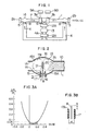
- the principal portion of a discharge tube l has a reflecting mirror 2a and an output mirror 2b at its two ends and ring-shaped cathodes 3a, 3b are disposed at the central portion, which are opposed to the mirrors 2a, 2b. Both the ends and the central portion of the principal part of the discharge tube l are connected to a gas flow path 4.
- the gas flow path 4 forms the gas inlets 5 and the gas outlet 6.
- the first and the second heat exchanger l2A, l2B and the blower l3 are disposed on the central tube 4A of the gas flow path 4.
- the gas medium 7 cooled by the second heat exchanger l2B flows through the gas flow path 4 and is ejected through the gas inlet 5 in each of the expansion chambers l4.
- Each of the expansion chambers l4 is an expanded portion of the principal portion of the discharge tube l, which is formed in an ellipsoid expanded in the gas inflow direction and the direction opposite thereto.
- Each of the expansion chambers l4 consists of a lower expanded portion l5 near the gas inlet and an upper expanded portion l6, which is opposite thereto.
- the two expanded portions are so formed that they are symmetric with respect to the axis of the principal portion of the discharge tube l.
- the lower expanded portion l5 is expanded outward from the inner surface lA of the principal portion of the discharge tube, i.e. it protrudes outward.
- a nozzle l7 is inserted in the gas inlet 5 in the lower expanded portion l5.
- a hole l8 which is connected with the gas flow path 4.
- a rod-shaped anode 8 Within the hole l8 is disposed a rod-shaped anode 8.
- the lower end of the anode 8 is bent in an L-shape and the anode is mounted on the inner surface of the nozzle l7 or the gas flow path.
- the nozzle l7 and the anode 8 protrude partly into the lower expanded portion.
- the size of the protrusion of the nozzle l7 and that of the anode 8 are so chosen that no parts of the nozzle l7 and the anode 8 protrude beyond the inner surface la of the principal portion of the discharge tube therein, i.e. in the laser beam path.
- the extremity or end of the anode is disposed usually nearer to the inner surface of the principal portion of the discharge tube than the extremity or end of the nozzle l7.
- the anode may be so formed that its extremity is at the same hight as the extremity of the nozzle l7.
- the gas medium 7 in the hole or aperture l8 is ejected in the expansion chamber l4.
- the ejected gas medium 7 elongates upward the ignited flame 20 on the anode 8 and forms it in a shape similar to that of a flame of candle.
- the ejected gas medium 7 forms a potential core 2l, whose diameter becomes smaller with increasing distance from the nozzle l7 to the ceiling surface l6A of the upper expanded portion l6.
- the ejected gas medium 7 collides with the ceiling surface l6A and is divided into two partial flows of different directions.
- One 7A of the partial flows of the gas medium flows to the glow discharge domain and the other 7B circulates along the inner surface of the expansion chamber, then collides with the nozzle l7 along the inner surface of the lower expanded portion l5, flows around the nozzle l7 and finally flows to the glow discharge domain l0.
- the partial flows 7B of the gas medium collides with the gas medium 7 or the potential core 2l in the lower expanded portion. Since the gas medium 7 or the potential core 2l do not fluctuate much, the flame 20 also does not fluctuate. Thus, it is slender and long and it elongates straight. Consequently the glow discharge domain l0 also does not oscillate and is stable.
- the laser beam ll emitted through the output mirror 2b fluctuates only slightly and its output power is always stable.
- the inventors of this invention have observed that the fluctuations of the laser beam were reduced to about l/l0 according to this invention with respect to those observed according to the prior art techniques.
- the abscissa in Fig. 3A represents the ratio of the distance H between the extremity of the anode 8 and the extremity surface l7A of the nozzle l7 to the diameter d of the nozzle as indicated in Fig. 3B, which distance is increased successively.
- the ordinate indicates the ratio ⁇ P L /P L of fluctuations ⁇ P L of the laser beam to the average output power P L of the laser beam.
- another nozzle l7A is disposed outside of the nozzle l7 so that a cylindrical hole l8A is formed between the nozzles l7 and l7A.
- the total cross-section of the holes l8 and l8A can be increased and thus it is possible to reduce the whole pressure loss in the gas inlet 5. Consequently the gas flow rate and the output power of the laser beam can be increased. Further, at the same time, since the gas medium coming from the peripheral hole flows, surrounding the potential core 2l, what has an effect that the potential core is hardly disturbed.
- the expanded portion l5 protruding outward is formed only at the neighborhood of the gas inlet 5 of the principal portion of the gas discharge tube l.
- the expansion chamber l4A is a rectangular parallelepiped.
- the anode 8 is disposed outside of the nozzle and extended to the vicinity of the central axis of the cylindrical hole l8. In any case an effect similar to that described above can be achieved.
- the object of this invention can be achieved by disposing any expanded portion at least on the gas inlet side of the expansion chamber, but a greater effect can be obtained, if the expansion chamber is a sphere, an oval or an ellipsoid, which is symmetric with respect to the central axis of the discharge tube. Further it is a cylindrical nozzle that has most excellent characteristics, but a tapered inner or outer periphery has an effect and its cross-sectional form may be other than a circle.
- the nozzle l7 may protrude beyond the inner surface of the principal portion of the discharge tube in such an extent that it does not hinder the laser beam path.
- the inner diameter of the principal portion of the discharge tube at the neighborhood of the nozzle is greater than that at the glow discharge domain.
- the gas laser device according to this invention can stabilize the laser output power.
Landscapes
- Physics & Mathematics (AREA)
- Electromagnetism (AREA)
- Engineering & Computer Science (AREA)
- Plasma & Fusion (AREA)
- Optics & Photonics (AREA)
- Lasers (AREA)
Applications Claiming Priority (2)
| Application Number | Priority Date | Filing Date | Title |
|---|---|---|---|
| JP23077785 | 1985-10-16 | ||
| JP230777/85 | 1985-10-16 |
Publications (3)
| Publication Number | Publication Date |
|---|---|
| EP0236547A2 true EP0236547A2 (de) | 1987-09-16 |
| EP0236547A3 EP0236547A3 (en) | 1988-08-03 |
| EP0236547B1 EP0236547B1 (de) | 1992-08-19 |
Family
ID=16913097
Family Applications (1)
| Application Number | Title | Priority Date | Filing Date |
|---|---|---|---|
| EP86114208A Expired - Lifetime EP0236547B1 (de) | 1985-10-16 | 1986-10-14 | Gaslaservorrichtung |
Country Status (4)
| Country | Link |
|---|---|
| US (1) | US4740980A (de) |
| EP (1) | EP0236547B1 (de) |
| JP (1) | JPS62174989A (de) |
| DE (1) | DE3686484T2 (de) |
Cited By (1)
| Publication number | Priority date | Publication date | Assignee | Title |
|---|---|---|---|---|
| GB2235570A (en) * | 1989-08-29 | 1991-03-06 | Tzn Forschung & Entwicklung | Gas flow cooled laser |
Families Citing this family (2)
| Publication number | Priority date | Publication date | Assignee | Title |
|---|---|---|---|---|
| JPH01162263U (de) * | 1988-04-14 | 1989-11-10 | ||
| US10375901B2 (en) | 2014-12-09 | 2019-08-13 | Mtd Products Inc | Blower/vacuum |
Family Cites Families (5)
| Publication number | Priority date | Publication date | Assignee | Title |
|---|---|---|---|---|
| JPS55113391A (en) * | 1979-02-21 | 1980-09-01 | Hitachi Ltd | Gas flow type laser device |
| US4672621A (en) * | 1982-04-13 | 1987-06-09 | Matsushita Electric Industrial Co., Ltd. | Laser resonator having an improved gas-introducing portion |
| US4622675A (en) * | 1983-07-29 | 1986-11-11 | P.R.C., Ltd. | Forced transport molecular gas laser and method |
| GB8427549D0 (en) * | 1984-10-31 | 1984-12-05 | Jec Lasers Inc | Electric discharge apparatus |
| FR2573931B1 (fr) * | 1984-11-29 | 1987-01-02 | Comp Generale Electricite | Generateur laser a flux gazeux et procede de fonctionnement de ce generateur |
-
1986
- 1986-10-01 JP JP61231185A patent/JPS62174989A/ja active Pending
- 1986-10-14 EP EP86114208A patent/EP0236547B1/de not_active Expired - Lifetime
- 1986-10-14 DE DE8686114208T patent/DE3686484T2/de not_active Expired - Fee Related
- 1986-10-16 US US06/919,423 patent/US4740980A/en not_active Expired - Lifetime
Cited By (1)
| Publication number | Priority date | Publication date | Assignee | Title |
|---|---|---|---|---|
| GB2235570A (en) * | 1989-08-29 | 1991-03-06 | Tzn Forschung & Entwicklung | Gas flow cooled laser |
Also Published As
| Publication number | Publication date |
|---|---|
| EP0236547A3 (en) | 1988-08-03 |
| US4740980A (en) | 1988-04-26 |
| JPS62174989A (ja) | 1987-07-31 |
| DE3686484D1 (de) | 1992-09-24 |
| DE3686484T2 (de) | 1993-03-18 |
| EP0236547B1 (de) | 1992-08-19 |
Similar Documents
| Publication | Publication Date | Title |
|---|---|---|
| US4841538A (en) | CO2 gas laser device | |
| US4331939A (en) | Gas laser device | |
| US4740980A (en) | Gas laser device | |
| US4597086A (en) | Coaxial type laser oscillator for excitation by silent discharge | |
| US4993037A (en) | High speed axial flow gas laser generator | |
| JPH06105812B2 (ja) | 高速軸流形レーザ発振器 | |
| JP2706353B2 (ja) | ガスレーザ発振装置 | |
| JPH0318749B2 (de) | ||
| JPS631086A (ja) | ガスレ−ザ発振器 | |
| JPS613484A (ja) | ガスレ−ザ装置 | |
| JP2693004B2 (ja) | ガスレーザ発振装置 | |
| JPS6328517B2 (de) | ||
| CN120262141A (zh) | 一种输出脉冲激光的二氧化碳玻璃管激光器 | |
| JPS6076181A (ja) | 高速軸流形ガスレ−ザ発振器 | |
| JPS6114780A (ja) | ガスレ−ザ発生器 | |
| JPH03254167A (ja) | 軸流気体レーザ発振器 | |
| JPH073655Y2 (ja) | 着脱可能なアパーチャーを有するレーザガス放電管のアノード電極構造 | |
| JPH02130973A (ja) | レーザ発振装置 | |
| JPS62189777A (ja) | ガスレ−ザ発振器 | |
| JPS6022621Y2 (ja) | ガスレ−ザ放電管 | |
| JPS61112389A (ja) | 高速軸流形ガスレ−ザ−装置 | |
| JPS6281781A (ja) | 炭酸ガスレ−ザ装置 | |
| JPS61174682A (ja) | ガスレ−ザ−およびその操作方法 | |
| JPS62196879A (ja) | ガスレ−ザ発振器 | |
| JPS6052070A (ja) | 同軸型レ−ザ発振器 |
Legal Events
| Date | Code | Title | Description |
|---|---|---|---|
| PUAI | Public reference made under article 153(3) epc to a published international application that has entered the european phase |
Free format text: ORIGINAL CODE: 0009012 |
|
| AK | Designated contracting states |
Kind code of ref document: A2 Designated state(s): CH DE FR GB IT LI NL SE |
|
| PUAL | Search report despatched |
Free format text: ORIGINAL CODE: 0009013 |
|
| AK | Designated contracting states |
Kind code of ref document: A3 Designated state(s): CH DE FR GB IT LI NL SE |
|
| 17P | Request for examination filed |
Effective date: 19890104 |
|
| 17Q | First examination report despatched |
Effective date: 19910222 |
|
| GRAA | (expected) grant |
Free format text: ORIGINAL CODE: 0009210 |
|
| AK | Designated contracting states |
Kind code of ref document: B1 Designated state(s): CH DE FR GB IT LI NL SE |
|
| PG25 | Lapsed in a contracting state [announced via postgrant information from national office to epo] |
Ref country code: IT Free format text: LAPSE BECAUSE OF FAILURE TO SUBMIT A TRANSLATION OF THE DESCRIPTION OR TO PAY THE FEE WITHIN THE PRE;WARNING: LAPSES OF ITALIAN PATENTS WITH EFFECTIVE DATE BEFORE 2007 MAY HAVE OCCURRED AT ANY TIME BEFORE 2007. THE CORRECT EFFECTIVE DATE MAY BE DIFFERENT FROM THE ONE RECORDED.SCRIBED TIME-LIMIT Effective date: 19920819 Ref country code: CH Effective date: 19920819 Ref country code: SE Free format text: THE PATENT HAS BEEN ANNULLED BY A DECISION OF A NATIONAL AUTHORITY Effective date: 19920819 Ref country code: LI Effective date: 19920819 Ref country code: NL Effective date: 19920819 |
|
| REF | Corresponds to: |
Ref document number: 3686484 Country of ref document: DE Date of ref document: 19920924 |
|
| ET | Fr: translation filed | ||
| REG | Reference to a national code |
Ref country code: CH Ref legal event code: PL |
|
| NLV1 | Nl: lapsed or annulled due to failure to fulfill the requirements of art. 29p and 29m of the patents act | ||
| PLBE | No opposition filed within time limit |
Free format text: ORIGINAL CODE: 0009261 |
|
| STAA | Information on the status of an ep patent application or granted ep patent |
Free format text: STATUS: NO OPPOSITION FILED WITHIN TIME LIMIT |
|
| 26N | No opposition filed | ||
| REG | Reference to a national code |
Ref country code: GB Ref legal event code: IF02 |
|
| PGFP | Annual fee paid to national office [announced via postgrant information from national office to epo] |
Ref country code: FR Payment date: 20020923 Year of fee payment: 17 |
|
| PGFP | Annual fee paid to national office [announced via postgrant information from national office to epo] |
Ref country code: GB Payment date: 20020926 Year of fee payment: 17 |
|
| PGFP | Annual fee paid to national office [announced via postgrant information from national office to epo] |
Ref country code: DE Payment date: 20021205 Year of fee payment: 17 |
|
| PG25 | Lapsed in a contracting state [announced via postgrant information from national office to epo] |
Ref country code: GB Free format text: LAPSE BECAUSE OF NON-PAYMENT OF DUE FEES Effective date: 20031014 |
|
| PG25 | Lapsed in a contracting state [announced via postgrant information from national office to epo] |
Ref country code: DE Free format text: LAPSE BECAUSE OF NON-PAYMENT OF DUE FEES Effective date: 20040501 |
|
| GBPC | Gb: european patent ceased through non-payment of renewal fee |
Effective date: 20031014 |
|
| PG25 | Lapsed in a contracting state [announced via postgrant information from national office to epo] |
Ref country code: FR Free format text: LAPSE BECAUSE OF NON-PAYMENT OF DUE FEES Effective date: 20040630 |
|
| REG | Reference to a national code |
Ref country code: FR Ref legal event code: ST |