EP0236603A1 - Getriebe eines Revolverkopfes bestehend aus einer Zwillingsscheibe für CNC-Maschinen - Google Patents
Getriebe eines Revolverkopfes bestehend aus einer Zwillingsscheibe für CNC-Maschinen Download PDFInfo
- Publication number
- EP0236603A1 EP0236603A1 EP86301622A EP86301622A EP0236603A1 EP 0236603 A1 EP0236603 A1 EP 0236603A1 EP 86301622 A EP86301622 A EP 86301622A EP 86301622 A EP86301622 A EP 86301622A EP 0236603 A1 EP0236603 A1 EP 0236603A1
- Authority
- EP
- European Patent Office
- Prior art keywords
- disc
- tool
- turret
- tools
- twin
- Prior art date
- Legal status (The legal status is an assumption and is not a legal conclusion. Google has not performed a legal analysis and makes no representation as to the accuracy of the status listed.)
- Granted
Links
- 230000007246 mechanism Effects 0.000 title claims abstract description 30
- 230000008878 coupling Effects 0.000 claims abstract description 15
- 238000010168 coupling process Methods 0.000 claims abstract description 15
- 238000005859 coupling reaction Methods 0.000 claims abstract description 15
- 239000000523 sample Substances 0.000 claims abstract description 13
- 238000005259 measurement Methods 0.000 claims abstract description 4
- 239000002173 cutting fluid Substances 0.000 claims description 10
- 238000003754 machining Methods 0.000 claims description 5
- 230000001939 inductive effect Effects 0.000 claims description 3
- 230000008054 signal transmission Effects 0.000 claims description 3
- 238000005553 drilling Methods 0.000 claims 1
- 238000003801 milling Methods 0.000 claims 1
- 238000000034 method Methods 0.000 abstract description 3
- 238000012545 processing Methods 0.000 abstract description 3
- 239000012530 fluid Substances 0.000 description 19
- 230000001965 increasing effect Effects 0.000 description 6
- 230000009471 action Effects 0.000 description 5
- 230000005540 biological transmission Effects 0.000 description 3
- 238000013459 approach Methods 0.000 description 1
- 238000013461 design Methods 0.000 description 1
- 230000008030 elimination Effects 0.000 description 1
- 238000003379 elimination reaction Methods 0.000 description 1
- 238000003780 insertion Methods 0.000 description 1
- 230000037431 insertion Effects 0.000 description 1
- 238000010187 selection method Methods 0.000 description 1
Images


Classifications
-
- B—PERFORMING OPERATIONS; TRANSPORTING
- B23—MACHINE TOOLS; METAL-WORKING NOT OTHERWISE PROVIDED FOR
- B23B—TURNING; BORING
- B23B29/00—Holders for non-rotary cutting tools; Boring bars or boring heads; Accessories for tool holders
- B23B29/24—Tool holders for a plurality of cutting tools, e.g. turrets
- B23B29/32—Turrets adjustable by power drive, i.e. turret heads
- B23B29/323—Turrets with power operated angular positioning devices
-
- B—PERFORMING OPERATIONS; TRANSPORTING
- B23—MACHINE TOOLS; METAL-WORKING NOT OTHERWISE PROVIDED FOR
- B23B—TURNING; BORING
- B23B3/00—General-purpose turning-machines or devices, e.g. centre lathes with feed rod and lead screw; Sets of turning-machines
- B23B3/16—Turret lathes for turning individually-chucked workpieces
- B23B3/164—Turret lathes for turning individually-chucked workpieces lathe with one toolslide carrying two or more turret heads
-
- B—PERFORMING OPERATIONS; TRANSPORTING
- B23—MACHINE TOOLS; METAL-WORKING NOT OTHERWISE PROVIDED FOR
- B23Q—DETAILS, COMPONENTS, OR ACCESSORIES FOR MACHINE TOOLS, e.g. ARRANGEMENTS FOR COPYING OR CONTROLLING; MACHINE TOOLS IN GENERAL CHARACTERISED BY THE CONSTRUCTION OF PARTICULAR DETAILS OR COMPONENTS; COMBINATIONS OR ASSOCIATIONS OF METAL-WORKING MACHINES, NOT DIRECTED TO A PARTICULAR RESULT
- B23Q1/00—Members which are comprised in the general build-up of a form of machine, particularly relatively large fixed members
- B23Q1/0009—Energy-transferring means or control lines for movable machine parts; Control panels or boxes; Control parts
- B23Q1/0018—Energy-transferring means or control lines for movable machine parts; Control panels or boxes; Control parts comprising hydraulic means
-
- B—PERFORMING OPERATIONS; TRANSPORTING
- B23—MACHINE TOOLS; METAL-WORKING NOT OTHERWISE PROVIDED FOR
- B23Q—DETAILS, COMPONENTS, OR ACCESSORIES FOR MACHINE TOOLS, e.g. ARRANGEMENTS FOR COPYING OR CONTROLLING; MACHINE TOOLS IN GENERAL CHARACTERISED BY THE CONSTRUCTION OF PARTICULAR DETAILS OR COMPONENTS; COMBINATIONS OR ASSOCIATIONS OF METAL-WORKING MACHINES, NOT DIRECTED TO A PARTICULAR RESULT
- B23Q17/00—Arrangements for observing, indicating or measuring on machine tools
- B23Q17/20—Arrangements for observing, indicating or measuring on machine tools for indicating or measuring workpiece characteristics, e.g. contour, dimension, hardness
-
- Y—GENERAL TAGGING OF NEW TECHNOLOGICAL DEVELOPMENTS; GENERAL TAGGING OF CROSS-SECTIONAL TECHNOLOGIES SPANNING OVER SEVERAL SECTIONS OF THE IPC; TECHNICAL SUBJECTS COVERED BY FORMER USPC CROSS-REFERENCE ART COLLECTIONS [XRACs] AND DIGESTS
- Y10—TECHNICAL SUBJECTS COVERED BY FORMER USPC
- Y10T—TECHNICAL SUBJECTS COVERED BY FORMER US CLASSIFICATION
- Y10T29/00—Metal working
- Y10T29/51—Plural diverse manufacturing apparatus including means for metal shaping or assembling
- Y10T29/5152—Plural diverse manufacturing apparatus including means for metal shaping or assembling with turret mechanism
- Y10T29/5154—Plural diverse manufacturing apparatus including means for metal shaping or assembling with turret mechanism tool turret
-
- Y—GENERAL TAGGING OF NEW TECHNOLOGICAL DEVELOPMENTS; GENERAL TAGGING OF CROSS-SECTIONAL TECHNOLOGIES SPANNING OVER SEVERAL SECTIONS OF THE IPC; TECHNICAL SUBJECTS COVERED BY FORMER USPC CROSS-REFERENCE ART COLLECTIONS [XRACs] AND DIGESTS
- Y10—TECHNICAL SUBJECTS COVERED BY FORMER USPC
- Y10T—TECHNICAL SUBJECTS COVERED BY FORMER US CLASSIFICATION
- Y10T74/00—Machine element or mechanism
- Y10T74/14—Rotary member or shaft indexing, e.g., tool or work turret
- Y10T74/1476—Rotary member or shaft indexing, e.g., tool or work turret with means to axially shift shaft
-
- Y—GENERAL TAGGING OF NEW TECHNOLOGICAL DEVELOPMENTS; GENERAL TAGGING OF CROSS-SECTIONAL TECHNOLOGIES SPANNING OVER SEVERAL SECTIONS OF THE IPC; TECHNICAL SUBJECTS COVERED BY FORMER USPC CROSS-REFERENCE ART COLLECTIONS [XRACs] AND DIGESTS
- Y10—TECHNICAL SUBJECTS COVERED BY FORMER USPC
- Y10T—TECHNICAL SUBJECTS COVERED BY FORMER US CLASSIFICATION
- Y10T82/00—Turning
- Y10T82/25—Lathe
- Y10T82/2531—Carriage feed
- Y10T82/2541—Slide rest
- Y10T82/2543—Multiple tool support
-
- Y—GENERAL TAGGING OF NEW TECHNOLOGICAL DEVELOPMENTS; GENERAL TAGGING OF CROSS-SECTIONAL TECHNOLOGIES SPANNING OVER SEVERAL SECTIONS OF THE IPC; TECHNICAL SUBJECTS COVERED BY FORMER USPC CROSS-REFERENCE ART COLLECTIONS [XRACs] AND DIGESTS
- Y10—TECHNICAL SUBJECTS COVERED BY FORMER USPC
- Y10T—TECHNICAL SUBJECTS COVERED BY FORMER US CLASSIFICATION
- Y10T82/00—Turning
- Y10T82/25—Lathe
- Y10T82/2585—Tool rest
- Y10T82/2587—Turret type holder [e.g., multiple tools, etc.]
Definitions
- This invention relates to a new tool turret mechanism and more particularly to a twin disc tool turret mechanism for CNC machines with two tool-mounting discs attached separately to a toothed ring-type three piece registration and lock-up coupling device (commercially designated as Curvic or Hirth coupling, hereinafter referred to as "three piece coupling device").
- a twin disc tool turret mechanism for CNC machines with two tool-mounting discs attached separately to a toothed ring-type three piece registration and lock-up coupling device (commercially designated as Curvic or Hirth coupling, hereinafter referred to as "three piece coupling device”).
- NC lathes have one or two tool turrets on which a number of either outside (OD) turning or inside (ID) boring tools are mounted.
- Cutting tools are mounted on a symmetric polygon or circular disc which indexes (including rotating, registering and locking) at the same angulars interval according to the number of tools mounted.
- the registration and locking mechanism essential to reproduce the exact coordinate location of the cutting tools, generally uses either a two-piece or a three-piece toothed ring-type coupling device.
- the desired tool is selected by the indexing mechanism to take up the active position of the tool turret, then the entire turret on a carriage is moved to engage the active tool with the workpiece.
- inactive tools may make contact (interfere) with the workpiece and the workpiece-holding chuck before and/or during the machining operation.
- This interference may be reduced by special arrangements of tools in relation to the workpiece but cannot be totally eliminated. Therefore, the programmer of the lathe has to take interference into consideration.
- the quantity of tools can be increased only by increasing the size of the tool mounting disc. Increasing the disc size, however, makes the turret heavier, thus harder to move, and a larger disc also slows down the speed of disc rotation. Besides, for any given disc rotational speed, increasing the quantity of tools also increases the average time required for tool changes. For all the reasons mentioned above, the number of tools on most conventional tool turrets is restricted to twelve.
- the tool turret may be replaced with a single tool holding post, having an automatic tool changing mechanism similar to that of machining centers. This approach, however, is much more complicated and, therefore, more costly than a conventional tool turret.
- This invention involves a new tool turret mechanism for CNC machines having two tool mounting discs, a front one and a rear one, attached separately to two pieces of a three piece coupling device.
- this mechanism allows doubling of tool quantity on a tool turret without increasing the turret size.
- the front disc has a number of radially situated mounting slots for OD turning tools
- the rear disc is a polygon having the same number of facets as the front disc has slots, with each facet serving as a seat for mounting of an OD (radial) turning, an ID (axial) boring, a facing or a revolving tools.
- Both discs are respectively mounted at an end of their related hollow shafts, with the shaft of the front disc passing through the hollow shaft of the rear disc. Situated behind these discs is a locking/unlocking and disc rotating mechanism consisting of: 1) a hydraulic motor operating, 2) two differential gear trains, 3) a hydraulic cylinder and 4) a hydraulic control system for manipulation of the hydraulic fluid.
- both thses discs can rotate in either direction so that the desired tool can be reached in the direction providing a shorter path for speedy tool selection.
- the OD tools are so arranged that all tools clear from all shanks of ID tools, and one seat on the rear disc is left vacant so that an active OD tool can reach the workpiece without interference from the tool which may otherwise be located at the active position.
- the configuration of the hollow shafts and the discs is so arranged that cutting fluid is supplied only to the active tool.
- the turret can also be modified to include a live spindle drive mechanism for actuation of revolving tools to be mounted on the rear disc.
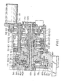
- Fig. 1 is a sectional illustrative view of a preferred embodiment of a twin disc tool turret mechanism according to this invention
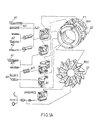
- Fig. 1A which is a three-dimentional illustrative view of two tool mounting discs
- Fig. 1B which is a partial three-dimensional illustrative view of a three piece coupling device and a cam arrangement
- the preferred embodiment comprises a front external (OD) turning tool mounting disc D1 and a rear tool mounting disc D2, operatively connected to a turret housing unit TH1.
- the front disc D1 is connected to a first hollow shaft S1, which passes through a second hollow shaft S2 connected to the rear disc D2.
- the front disc D1 is provided with twelve radial slots RS1 for mounting OD turning tool (A1) shanks A11 and the rear disc D2 is a dodecahedron, with facets F1 formed on its perimeter for mounting ID boring tool (A2) holders A22 as shown in Fig. 1A.
- a drive mechanism for rotation of the discs Situated behind these discs is a drive mechanism for rotation of the discs.
- the drive mechanism consists of a hydraulic motor M1 and a plurality of gears.
- the gear G10 mounted on the motor shaft is engaged to a differential gear set G00.
- a bevel gear G01 of the differential gear set G00 is connected to the second shaft S2 and the gear G03 through a key K1.
- Gear G21 and G22 There are two gears G21 and G22 arranged on the second shaft S2.
- Gear G21 is connected to the shaft S2 by a key K2 while G22 is an idler gear (only sleeved on the shaft thus is free to rotate) on the second shaft S2, but gear G22 has a built-in bevel gear engaged with the bevel gear G02.
- Gears G21 and G22 are separately engaged with gears G11 and G12 on the first shaft S1.
- the gear G12 is keyed to the first shaft S1 while gear G11 is an idler gear (only sleeved on the shaft S1).
- the gears G11 and G12 are respectively fixed to a pair of cams C1 and C2, and each cam has a plurality of tapered slots H1 and H2 (H1 on C1 and H2 on C2) which respectively correspond through the gear train to the tool mounting positions of both discs D1 and D2 so as to correspond with the lockup of the discs D1 and D2 in tool selection, which, on being finished, one of the tapered locating rods P1 or P2 from a pair of locating valves V1 and V2 is inserted into the aligned slot (H1 for P2 and H2 for P1), and the discs D1 or D2 is thereby locked in position for processing operation.
- the quantity of slots separately provided in the cams C1 and C2 differs.
- the quantity of slots H1 in cam C1 is nine while the quantity of slots H2 in cam C2 is twelve.
- the reason for this different arrangement is that the number of slots H1 is coordinated with the gears disposed on the transmission mechanism of the rear disc D2 so that whenever the rear disc D2 is stopped at any exact position, there is a slot H1 (one of the nine slots) exactly aligned with the stopped position of the rear disc D2.
- each one of the twelve positions of disc D1 corresponds to one of the twelve slots H2 of cam C2.
- the complete insertion of a locating rod into a slot in the cam locks the cam, the related shaft and therefore the disc at the exact position where the selected tool takes the active (cutting) position. Therefore, the engagement and disengagement of the tip of the locating rod P2 into and out of one of the slots H1 and that of the rod P1 out of one of the slots H2, when combined with the action of the hydraulic cylinder described in the following paragraph, actuate the locking and unlocking of the front and rear discs D1 and D2.
- a hydraulic cylinder HC1 is provided on the first hollow shaft S1 to move the shaft in or out therefrom.
- the mounting discs D1 and D2 are connected to the turret housing TH1 through a three piece coupling device RC10, which consists of an external toothed ring RC12, an internal toothed ring RC13 and a single sided toothed ring RC11 as shown in Fig. 1B (1), a partial three-dimensional illustrative view of a three piece coupling device.
- the external toothed ring RC12 is bolted to the rear disc D2, the internal toothed ring RC13 to the turret housing unit TH1 and the single sided tooth ring RC11 is bolted to the front disc D1.
- the single sided toothed ring RC11 is normally in tight engagement with the external toothed ring RC12 and the internal toothed ring RC13.
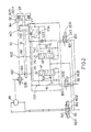
- Fig. 2 depicts a schematic hydraulic system of the twin disc tool turret mechanism according to this invention.
- the main components of this hydraulic system include a pair of locating valves V1 and V2, each having a locating rod P1, P2. These valves and rods not only switch the flow direction of hydraulic fluid but also activate and deactivate the first and second shafts S1 and S2 through the gear train and cams C2 and C1.
- the hydraulic motor M1, differential gear G00 and a fluid source FS1 are also depicted.
- Three solenoid valves SV1, SV2 and SV3 are utilized for control action.
- the locating rod P1 of the valve V1 is inserted into the slot H2 of the cam C2 and locating rod P2 of valve V2 into slot H1 of cam C1 as shown in Fig. 1B(2). Both front disc D1 and rear disc D2 are thereby lolidly locked.
- Hydraulic motor M1 transmits power to the differential gear set G00. Since the second shaft S2 is locked, and the bevel gear G01 is also locked, the power can only be transmitted from gear G22 to gear G12 via the bevel gear G02 to rotate the first shaft S1, thereby rotating the front disc D1 until a desired tool reaches the active location.
- a rotary limit switch mounted on the disc actuates a relay to deactivate coil EC12 which then diverts the fluid to enter valve V1 via port B23, thereby pushing the rod P1 back into a H2 slot.
- the stroking of valve V1 reduces its own internal throttling gap which reduces the quantity of hydraulic fluid reaching the hydraulic motor M1, effectively causing a braking action on the motor.
- the braking action slows down rotation of the cam C2 to facilitate alignment of the rod P1 with a H2 slot.
- An additional step to be described in th following paragraph manipulates the rear disc D2 for the vacated seat to assume the active position so that the active OD tool on the front disc D1 can reach a workpiece without interference from a tool on the active position of the rear disc D2.
- the tool selection procedure of the rear disc D2 is accomplished in the same manner as that of the front disc D1 described above.
- the coil EC11 or EC12 of valve SV1 and the coil EC31 of valve SV3 are activated.
- the hydraulic fluid from motor M1 passes through a port B32 to pull back the locating rod P2 from cam C1.
- the hydraulic fluid flows through a check valve CV3 to activate cylinder HC1 and cause the single sided toothed ring RC11 to disengage from the external toothed ring RC12 and the internal toothed ring RC13 so that the rear disc D2 is free to be rotated thereat.
- the hydraulic fluid passes from valve SV1 through motor M1, port B13, valve V2 and a throttle valve TV2 to reach the reservoir R2 so as to regulate the revolving speed of motor M1 from which the power is transmitted to differential gear set G00.
- the related gear G12 and the first shaft S1 are also locked in position, and the front disc D1 is thereby held inactive thereat.
- gears G10 and G03 of the gear train connected to motor M1 for power transmission are also locked.
- the power from motor M1 is transmitted through bevel gear G01 to the second shaft S2, which, in turn, relays the power to an inner gear set IG1 installed on the second shaft S2, and the rear disc D2 is hereby rotated until a desired tool reaches the active location thereat.
- coil EC31 of valve SV3 is deactivated, and the hydraulic fluid passes through port B3 into valve V2 to push out the locating rod P2.
- Fig. 1 which is a sectional illustrative view of the preferred embodiment
- Fig. 3 which is an illustrative sectional view of a revolving tool holder to be installed in the preferred embodiment
- a revolving tool T2 Actuation of a revolving tool T2 is accomplished by addition of a gear train G31 and G32 inside the turret housing unit TH1 so that the gear G31 of the revolving tool holder T10 meshes with the gear G32 at the end of a tool selection cycle.
- This design allows revolving tool holders T10 to be installed on any of the tool mounting holes MH1 provided on the rear disc D2.
- OD probe PR1 is mounted on one of the tool positions of disc D1, and ID probe PR2 on the position originally vacated for elimination of interference with OD turning.
- a signal from the probe PR1 is transmitted through inter disc contacts TT1 to TT2, then through the inductive signal transmission devices TT3 and TT4.
- Device TT4 is connected to the machine control unit by transmission cable.
- the signal can be transmitted directly through the inductive signal transmission devices TT3 and TT4.
- the essential function of supplying cutting fluid to an active tool on tool turret is also provided in this invention.
- Cutting fluid from a cutting fluid source FS1 passes through the first hollow shaft S1 to a directional orifice D01 which directs fluid to an active tool only when one of inlet holes IH1 on each of the tool positions is lined up with D01.
- a special supply hole SH1 is provided on disc D1 which, when positioned to take in cutting fluid, allows fluid to pass from opening OP1 on disc D1 to OP2 on disc D2, which in turn supplies fluid to the active tool A2.
- the opening OP2 is provided on each tool position on disc D2 but can receive cutting fluid only when it is lined up with the opening OP1. Therefore, cutting fluid is supplied only to a tool in the active position.
Landscapes
- Engineering & Computer Science (AREA)
- Mechanical Engineering (AREA)
- Cutting Tools, Boring Holders, And Turrets (AREA)
- Body Structure For Vehicles (AREA)
- Transmissions By Endless Flexible Members (AREA)
- Gear-Shifting Mechanisms (AREA)
Priority Applications (4)
| Application Number | Priority Date | Filing Date | Title |
|---|---|---|---|
| US06/837,393 US4706351A (en) | 1986-03-07 | 1986-03-07 | Twin disc type tool turret mechanism for CNC machines |
| EP86301622A EP0236603B1 (de) | 1986-03-07 | 1986-03-07 | Getriebe eines Revolverkopfes bestehend aus einer Zwillingsscheibe für CNC-Maschinen |
| DE8686301622T DE3676078D1 (de) | 1986-03-07 | 1986-03-07 | Getriebe eines revolverkopfes bestehend aus einer zwillingsscheibe fuer cnc-maschinen. |
| AT86301622T ATE58855T1 (de) | 1986-03-07 | 1986-03-07 | Getriebe eines revolverkopfes bestehend aus einer zwillingsscheibe fuer cnc-maschinen. |
Applications Claiming Priority (1)
| Application Number | Priority Date | Filing Date | Title |
|---|---|---|---|
| EP86301622A EP0236603B1 (de) | 1986-03-07 | 1986-03-07 | Getriebe eines Revolverkopfes bestehend aus einer Zwillingsscheibe für CNC-Maschinen |
Publications (2)
| Publication Number | Publication Date |
|---|---|
| EP0236603A1 true EP0236603A1 (de) | 1987-09-16 |
| EP0236603B1 EP0236603B1 (de) | 1990-12-05 |
Family
ID=8195917
Family Applications (1)
| Application Number | Title | Priority Date | Filing Date |
|---|---|---|---|
| EP86301622A Expired - Lifetime EP0236603B1 (de) | 1986-03-07 | 1986-03-07 | Getriebe eines Revolverkopfes bestehend aus einer Zwillingsscheibe für CNC-Maschinen |
Country Status (4)
| Country | Link |
|---|---|
| US (1) | US4706351A (de) |
| EP (1) | EP0236603B1 (de) |
| AT (1) | ATE58855T1 (de) |
| DE (1) | DE3676078D1 (de) |
Cited By (2)
| Publication number | Priority date | Publication date | Assignee | Title |
|---|---|---|---|---|
| US5093973A (en) * | 1989-10-24 | 1992-03-10 | Emag Maschinenfabrik Gmbh | Tool turret for machine tools |
| WO1994000260A1 (de) * | 1992-06-20 | 1994-01-06 | Pittler Gmbh | Doppelrevolver-werkzeughalter für eine drehmaschine |
Families Citing this family (16)
| Publication number | Priority date | Publication date | Assignee | Title |
|---|---|---|---|---|
| DE3738059C1 (de) * | 1987-11-09 | 1989-04-20 | Kurt Jauch | Drehautomat mit drehantreibbarem Werkzeugkopf und Fuehrungseinrichtung fuer Werkstoffstangen |
| DE3817873A1 (de) * | 1988-05-26 | 1989-11-30 | Sauter Kg Feinmechanik | Werkzeugrevolver |
| DE3817937A1 (de) * | 1988-05-26 | 1989-11-30 | Sauter Kg Feinmechanik | Werkzeugrevolver |
| DE4211348C2 (de) * | 1992-04-04 | 1994-06-23 | Chiron Werke Gmbh | Energieführungsleitung an einer Werkzeugmaschine mit einem Drehtisch |
| US5341551A (en) * | 1992-05-15 | 1994-08-30 | Kennametal Inc. | Universal turret system for quick-change lathe tooling |
| DE69614496T2 (de) * | 1996-01-05 | 2002-07-11 | Duplomatic Automazione S.P.A., Busto Arsizio | Werkzeugrevolver |
| US6122808A (en) * | 2000-02-11 | 2000-09-26 | Industrial Technology Research Institute | Oil conduit mechanism for spindle head of five axis machine tool |
| DE10044915B4 (de) * | 2000-09-12 | 2007-07-26 | Albeck Gmbh | Spannvorrichtung, insbesondere für mehrseitig zu bearbeitende Werkstücke |
| ITPD20020193A1 (it) * | 2002-07-12 | 2004-01-12 | Mei Srl | Unita' di alesatura per pezzi complessi, particolarmente per manigliedi porte, con sistema differenziale |
| CN100349677C (zh) * | 2004-04-19 | 2007-11-21 | 远东机械工业股份有限公司 | 双刀塔的刀塔座结构 |
| US7010839B2 (en) * | 2004-04-20 | 2006-03-14 | Factory Automation Technology Co., Ltd. | Structure of a twin disc type tool turret mechanism for CNC machines |
| US7263915B2 (en) * | 2005-05-13 | 2007-09-04 | Far East Machinery Co., Ltd. | Structure of a twin disc type tool turret device of a machine |
| US7437811B1 (en) * | 2007-06-20 | 2008-10-21 | Far East Machinery Co., Ltd. | Structure of a dual disc type of tool turret device of a machine |
| IT1401535B1 (it) * | 2009-10-02 | 2013-07-26 | Hardinge Inc | Portautensili |
| US20160263660A1 (en) * | 2015-03-09 | 2016-09-15 | Jose Lopez | Multipurpose Cutting Assembly |
| TWI623372B (zh) * | 2016-05-20 | 2018-05-11 | Tool machine turret high-pressure cutting fluid water guiding device |
Citations (4)
| Publication number | Priority date | Publication date | Assignee | Title |
|---|---|---|---|---|
| US3798721A (en) * | 1971-06-09 | 1974-03-26 | Gildemeister Werkzeugmasch | Indexible tool turret assembly |
| GB1458163A (en) * | 1974-07-08 | 1976-12-08 | Pittler Ag Maschf | Automatic utrret lathes |
| GB1508328A (en) * | 1974-08-30 | 1978-04-19 | Giddings & Lewis | Turret lathe |
| US4180894A (en) * | 1977-08-20 | 1980-01-01 | Index-Werke Kommanditgesellschaft Hahn & Tessky | Automatic turret lathe |
Family Cites Families (10)
| Publication number | Priority date | Publication date | Assignee | Title |
|---|---|---|---|---|
| US2685122A (en) * | 1951-05-26 | 1954-08-03 | Machines Outils Et D Outil S P | Turret-head for machine-tools with rotating spindle such as milling and boring machines and the like |
| US3246543A (en) * | 1963-07-17 | 1966-04-19 | Davidson Optronics Inc | Indexing fixture |
| DE1904457A1 (de) * | 1969-01-30 | 1970-08-20 | Monforts Fa A | Werkzeugmaschine mit verschwenkbarem Werkzeugschlitten |
| US3618427A (en) * | 1969-10-21 | 1971-11-09 | Warner Swasey Co | Locating means for indexing table |
| US3846912A (en) * | 1972-01-10 | 1974-11-12 | R Newbould | Indexing mechanism |
| CH580455A5 (de) * | 1975-03-27 | 1976-10-15 | Fischer Ag Georg | |
| DE2656608A1 (de) * | 1975-12-22 | 1977-06-30 | Smt Machine Co Ab | Werkzeugrevolver |
| GB1605143A (en) * | 1978-05-26 | 1982-02-10 | Herbert Ltd A | Machine tool |
| DE3202042C2 (de) * | 1982-01-23 | 1987-01-22 | G. Boley GmbH & Co, Werkzeugmaschinenfabrik, 7300 Esslingen | Werkzeugrevolver für Werkzeugmaschinen, insbesondere Drehmaschinen |
| JP3343202B2 (ja) * | 1997-06-19 | 2002-11-11 | ブリヂストンスポーツ株式会社 | スポーツシューズ |
-
1986
- 1986-03-07 DE DE8686301622T patent/DE3676078D1/de not_active Expired - Fee Related
- 1986-03-07 AT AT86301622T patent/ATE58855T1/de not_active IP Right Cessation
- 1986-03-07 US US06/837,393 patent/US4706351A/en not_active Expired - Lifetime
- 1986-03-07 EP EP86301622A patent/EP0236603B1/de not_active Expired - Lifetime
Patent Citations (4)
| Publication number | Priority date | Publication date | Assignee | Title |
|---|---|---|---|---|
| US3798721A (en) * | 1971-06-09 | 1974-03-26 | Gildemeister Werkzeugmasch | Indexible tool turret assembly |
| GB1458163A (en) * | 1974-07-08 | 1976-12-08 | Pittler Ag Maschf | Automatic utrret lathes |
| GB1508328A (en) * | 1974-08-30 | 1978-04-19 | Giddings & Lewis | Turret lathe |
| US4180894A (en) * | 1977-08-20 | 1980-01-01 | Index-Werke Kommanditgesellschaft Hahn & Tessky | Automatic turret lathe |
Cited By (2)
| Publication number | Priority date | Publication date | Assignee | Title |
|---|---|---|---|---|
| US5093973A (en) * | 1989-10-24 | 1992-03-10 | Emag Maschinenfabrik Gmbh | Tool turret for machine tools |
| WO1994000260A1 (de) * | 1992-06-20 | 1994-01-06 | Pittler Gmbh | Doppelrevolver-werkzeughalter für eine drehmaschine |
Also Published As
| Publication number | Publication date |
|---|---|
| US4706351A (en) | 1987-11-17 |
| EP0236603B1 (de) | 1990-12-05 |
| DE3676078D1 (de) | 1991-01-17 |
| ATE58855T1 (de) | 1990-12-15 |
Similar Documents
| Publication | Publication Date | Title |
|---|---|---|
| EP0236603A1 (de) | Getriebe eines Revolverkopfes bestehend aus einer Zwillingsscheibe für CNC-Maschinen | |
| US4478540A (en) | Spindle head assembly with oblique axis of rotation | |
| JPS6374534A (ja) | 複合加工工作機械 | |
| JPH01264732A (ja) | 工作機械 | |
| JPH0749164B2 (ja) | Nc旋盤における往復台構造 | |
| JPH04261739A (ja) | 工具保持装置 | |
| JPH04275847A (ja) | 工作機械 | |
| EP1053811B1 (de) | Drehautomat und betriebsverfahren dafür | |
| KR20190083092A (ko) | 공작기계의 터렛 공구대 | |
| US3613192A (en) | Tool spindle assembly | |
| US5042126A (en) | Drive apparatus for multi-spindle processing machines | |
| US4887345A (en) | Turret apparatus | |
| US4715102A (en) | Machine tool | |
| US6257111B1 (en) | Automatic lathe and control method therefor | |
| CA1262621A (en) | Twin disc type tool turret mechanism for cnc machines | |
| GB1486524A (en) | Machine tools | |
| GB2208107A (en) | Revolving tool-carrier turret | |
| US3296896A (en) | Turret drills | |
| US7010839B2 (en) | Structure of a twin disc type tool turret mechanism for CNC machines | |
| JP4234504B2 (ja) | 工具タレット | |
| JPS6034202A (ja) | 数値制御旋盤の複合刃物台 | |
| JPH11188506A (ja) | 複合加工工作機械 | |
| JPH0314576B2 (de) | ||
| JP2717588B2 (ja) | 回転工具ユニットの回転指令方法 | |
| JP2954879B2 (ja) | 工作機械 |
Legal Events
| Date | Code | Title | Description |
|---|---|---|---|
| PUAI | Public reference made under article 153(3) epc to a published international application that has entered the european phase |
Free format text: ORIGINAL CODE: 0009012 |
|
| AK | Designated contracting states |
Kind code of ref document: A1 Designated state(s): AT BE CH DE FR GB IT LI LU NL SE |
|
| 17P | Request for examination filed |
Effective date: 19880226 |
|
| 17Q | First examination report despatched |
Effective date: 19890419 |
|
| GRAA | (expected) grant |
Free format text: ORIGINAL CODE: 0009210 |
|
| AK | Designated contracting states |
Kind code of ref document: B1 Designated state(s): AT BE CH DE FR GB IT LI LU NL SE |
|
| REF | Corresponds to: |
Ref document number: 58855 Country of ref document: AT Date of ref document: 19901215 Kind code of ref document: T |
|
| REF | Corresponds to: |
Ref document number: 3676078 Country of ref document: DE Date of ref document: 19910117 |
|
| ITF | It: translation for a ep patent filed | ||
| ET | Fr: translation filed | ||
| ITTA | It: last paid annual fee | ||
| PLBE | No opposition filed within time limit |
Free format text: ORIGINAL CODE: 0009261 |
|
| STAA | Information on the status of an ep patent application or granted ep patent |
Free format text: STATUS: NO OPPOSITION FILED WITHIN TIME LIMIT |
|
| 26N | No opposition filed | ||
| EPTA | Lu: last paid annual fee | ||
| EAL | Se: european patent in force in sweden |
Ref document number: 86301622.6 |
|
| PGFP | Annual fee paid to national office [announced via postgrant information from national office to epo] |
Ref country code: FR Payment date: 19960126 Year of fee payment: 11 |
|
| PGFP | Annual fee paid to national office [announced via postgrant information from national office to epo] |
Ref country code: GB Payment date: 19960227 Year of fee payment: 11 |
|
| PGFP | Annual fee paid to national office [announced via postgrant information from national office to epo] |
Ref country code: DE Payment date: 19960313 Year of fee payment: 11 Ref country code: AT Payment date: 19960313 Year of fee payment: 11 |
|
| PGFP | Annual fee paid to national office [announced via postgrant information from national office to epo] |
Ref country code: SE Payment date: 19960315 Year of fee payment: 11 |
|
| PGFP | Annual fee paid to national office [announced via postgrant information from national office to epo] |
Ref country code: CH Payment date: 19960322 Year of fee payment: 11 |
|
| PGFP | Annual fee paid to national office [announced via postgrant information from national office to epo] |
Ref country code: NL Payment date: 19960328 Year of fee payment: 11 |
|
| PGFP | Annual fee paid to national office [announced via postgrant information from national office to epo] |
Ref country code: LU Payment date: 19960401 Year of fee payment: 11 |
|
| PGFP | Annual fee paid to national office [announced via postgrant information from national office to epo] |
Ref country code: BE Payment date: 19960502 Year of fee payment: 11 |
|
| PG25 | Lapsed in a contracting state [announced via postgrant information from national office to epo] |
Ref country code: LU Free format text: LAPSE BECAUSE OF NON-PAYMENT OF DUE FEES Effective date: 19970307 Ref country code: GB Effective date: 19970307 Ref country code: AT Effective date: 19970307 |
|
| PG25 | Lapsed in a contracting state [announced via postgrant information from national office to epo] |
Ref country code: SE Effective date: 19970308 |
|
| PG25 | Lapsed in a contracting state [announced via postgrant information from national office to epo] |
Ref country code: LI Effective date: 19970331 Ref country code: CH Effective date: 19970331 Ref country code: BE Effective date: 19970331 |
|
| BERE | Be: lapsed |
Owner name: CHUANG KUO-HUEY Effective date: 19970331 |
|
| PG25 | Lapsed in a contracting state [announced via postgrant information from national office to epo] |
Ref country code: NL Effective date: 19971001 |
|
| GBPC | Gb: european patent ceased through non-payment of renewal fee |
Effective date: 19970307 |
|
| REG | Reference to a national code |
Ref country code: CH Ref legal event code: PL |
|
| PG25 | Lapsed in a contracting state [announced via postgrant information from national office to epo] |
Ref country code: FR Free format text: LAPSE BECAUSE OF NON-PAYMENT OF DUE FEES Effective date: 19971128 |
|
| NLV4 | Nl: lapsed or anulled due to non-payment of the annual fee |
Effective date: 19971001 |
|
| PG25 | Lapsed in a contracting state [announced via postgrant information from national office to epo] |
Ref country code: DE Effective date: 19971202 |
|
| EUG | Se: european patent has lapsed |
Ref document number: 86301622.6 |
|
| REG | Reference to a national code |
Ref country code: FR Ref legal event code: ST |
|
| PG25 | Lapsed in a contracting state [announced via postgrant information from national office to epo] |
Ref country code: IT Free format text: LAPSE BECAUSE OF NON-PAYMENT OF DUE FEES;WARNING: LAPSES OF ITALIAN PATENTS WITH EFFECTIVE DATE BEFORE 2007 MAY HAVE OCCURRED AT ANY TIME BEFORE 2007. THE CORRECT EFFECTIVE DATE MAY BE DIFFERENT FROM THE ONE RECORDED. Effective date: 20050307 |