EP0236608A1 - Système de distribution d'eau - Google Patents
Système de distribution d'eau Download PDFInfo
- Publication number
- EP0236608A1 EP0236608A1 EP86301746A EP86301746A EP0236608A1 EP 0236608 A1 EP0236608 A1 EP 0236608A1 EP 86301746 A EP86301746 A EP 86301746A EP 86301746 A EP86301746 A EP 86301746A EP 0236608 A1 EP0236608 A1 EP 0236608A1
- Authority
- EP
- European Patent Office
- Prior art keywords
- valve
- water
- reservoir
- pressure
- chamber
- Prior art date
- Legal status (The legal status is an assumption and is not a legal conclusion. Google has not performed a legal analysis and makes no representation as to the accuracy of the status listed.)
- Ceased
Links
- XLYOFNOQVPJJNP-UHFFFAOYSA-N water Substances O XLYOFNOQVPJJNP-UHFFFAOYSA-N 0.000 title claims abstract description 168
- 239000000463 material Substances 0.000 claims description 8
- 238000007789 sealing Methods 0.000 claims description 8
- 238000004891 communication Methods 0.000 claims description 6
- 230000000694 effects Effects 0.000 claims description 3
- 230000002093 peripheral effect Effects 0.000 claims description 3
- 230000000750 progressive effect Effects 0.000 claims description 3
- 230000000630 rising effect Effects 0.000 claims description 3
- 230000013011 mating Effects 0.000 claims 3
- 239000012858 resilient material Substances 0.000 claims 1
- 239000004033 plastic Substances 0.000 description 7
- 229920003023 plastic Polymers 0.000 description 7
- 210000002445 nipple Anatomy 0.000 description 6
- 238000010276 construction Methods 0.000 description 3
- 238000009434 installation Methods 0.000 description 3
- 239000011248 coating agent Substances 0.000 description 2
- 238000000576 coating method Methods 0.000 description 2
- 230000000295 complement effect Effects 0.000 description 2
- 230000008014 freezing Effects 0.000 description 2
- 238000007710 freezing Methods 0.000 description 2
- 238000010438 heat treatment Methods 0.000 description 2
- 238000009413 insulation Methods 0.000 description 2
- 239000002245 particle Substances 0.000 description 2
- 230000001105 regulatory effect Effects 0.000 description 2
- 230000003014 reinforcing effect Effects 0.000 description 2
- 230000003068 static effect Effects 0.000 description 2
- 239000004677 Nylon Substances 0.000 description 1
- 239000004793 Polystyrene Substances 0.000 description 1
- 230000002411 adverse Effects 0.000 description 1
- 238000000429 assembly Methods 0.000 description 1
- 230000000712 assembly Effects 0.000 description 1
- 230000015572 biosynthetic process Effects 0.000 description 1
- 230000000903 blocking effect Effects 0.000 description 1
- 238000006243 chemical reaction Methods 0.000 description 1
- IDLFZVILOHSSID-OVLDLUHVSA-N corticotropin Chemical compound C([C@@H](C(=O)N[C@@H](CO)C(=O)N[C@@H](CCSC)C(=O)N[C@@H](CCC(O)=O)C(=O)N[C@@H](CC=1NC=NC=1)C(=O)N[C@@H](CC=1C=CC=CC=1)C(=O)N[C@@H](CCCNC(N)=N)C(=O)N[C@@H](CC=1C2=CC=CC=C2NC=1)C(=O)NCC(=O)N[C@@H](CCCCN)C(=O)N1[C@@H](CCC1)C(=O)N[C@@H](C(C)C)C(=O)NCC(=O)N[C@@H](CCCCN)C(=O)N[C@@H](CCCCN)C(=O)N[C@@H](CCCNC(N)=N)C(=O)N[C@@H](CCCNC(N)=N)C(=O)N1[C@@H](CCC1)C(=O)N[C@@H](C(C)C)C(=O)N[C@@H](CCCCN)C(=O)N[C@@H](C(C)C)C(=O)N[C@@H](CC=1C=CC(O)=CC=1)C(=O)N1[C@@H](CCC1)C(=O)N[C@@H](CC(N)=O)C(=O)NCC(=O)N[C@@H](C)C(=O)N[C@@H](CCC(O)=O)C(=O)N[C@@H](CC(O)=O)C(=O)N[C@@H](CCC(O)=O)C(=O)N[C@@H](CO)C(=O)N[C@@H](C)C(=O)N[C@@H](CCC(O)=O)C(=O)N[C@@H](C)C(=O)N[C@@H](CC=1C=CC=CC=1)C(=O)N1[C@@H](CCC1)C(=O)N[C@@H](CC(C)C)C(=O)N[C@@H](CCC(O)=O)C(=O)N[C@@H](CC=1C=CC=CC=1)C(O)=O)NC(=O)[C@@H](N)CO)C1=CC=C(O)C=C1 IDLFZVILOHSSID-OVLDLUHVSA-N 0.000 description 1
- 230000001627 detrimental effect Effects 0.000 description 1
- 230000008020 evaporation Effects 0.000 description 1
- 238000001704 evaporation Methods 0.000 description 1
- 238000002474 experimental method Methods 0.000 description 1
- 239000006260 foam Substances 0.000 description 1
- 239000006261 foam material Substances 0.000 description 1
- 239000008236 heating water Substances 0.000 description 1
- 238000001746 injection moulding Methods 0.000 description 1
- 239000007788 liquid Substances 0.000 description 1
- 238000012423 maintenance Methods 0.000 description 1
- 238000004519 manufacturing process Methods 0.000 description 1
- 239000002184 metal Substances 0.000 description 1
- 238000012986 modification Methods 0.000 description 1
- 230000004048 modification Effects 0.000 description 1
- 238000000465 moulding Methods 0.000 description 1
- 229920003052 natural elastomer Polymers 0.000 description 1
- 229920001194 natural rubber Polymers 0.000 description 1
- 229920001778 nylon Polymers 0.000 description 1
- 229920002223 polystyrene Polymers 0.000 description 1
- 239000011253 protective coating Substances 0.000 description 1
- 230000002787 reinforcement Effects 0.000 description 1
- 230000000087 stabilizing effect Effects 0.000 description 1
- 239000008400 supply water Substances 0.000 description 1
- 229920003051 synthetic elastomer Polymers 0.000 description 1
- 239000005061 synthetic rubber Substances 0.000 description 1
- 238000010257 thawing Methods 0.000 description 1
- 239000002699 waste material Substances 0.000 description 1
Images


Classifications
-
- G—PHYSICS
- G05—CONTROLLING; REGULATING
- G05D—SYSTEMS FOR CONTROLLING OR REGULATING NON-ELECTRIC VARIABLES
- G05D16/00—Control of fluid pressure
- G05D16/04—Control of fluid pressure without auxiliary power
- G05D16/06—Control of fluid pressure without auxiliary power the sensing element being a flexible membrane, yielding to pressure, e.g. diaphragm, bellows, capsule
- G05D16/063—Control of fluid pressure without auxiliary power the sensing element being a flexible membrane, yielding to pressure, e.g. diaphragm, bellows, capsule the sensing element being a membrane
- G05D16/0644—Control of fluid pressure without auxiliary power the sensing element being a flexible membrane, yielding to pressure, e.g. diaphragm, bellows, capsule the sensing element being a membrane the membrane acting directly on the obturator
- G05D16/0647—Control of fluid pressure without auxiliary power the sensing element being a flexible membrane, yielding to pressure, e.g. diaphragm, bellows, capsule the sensing element being a membrane the membrane acting directly on the obturator using one membrane without spring
- G05D16/065—Control of fluid pressure without auxiliary power the sensing element being a flexible membrane, yielding to pressure, e.g. diaphragm, bellows, capsule the sensing element being a membrane the membrane acting directly on the obturator using one membrane without spring characterised by the form of the obturator
-
- F—MECHANICAL ENGINEERING; LIGHTING; HEATING; WEAPONS; BLASTING
- F16—ENGINEERING ELEMENTS AND UNITS; GENERAL MEASURES FOR PRODUCING AND MAINTAINING EFFECTIVE FUNCTIONING OF MACHINES OR INSTALLATIONS; THERMAL INSULATION IN GENERAL
- F16K—VALVES; TAPS; COCKS; ACTUATING-FLOATS; DEVICES FOR VENTING OR AERATING
- F16K31/00—Actuating devices; Operating means; Releasing devices
- F16K31/12—Actuating devices; Operating means; Releasing devices actuated by fluid
- F16K31/18—Actuating devices; Operating means; Releasing devices actuated by fluid actuated by a float
- F16K31/34—Actuating devices; Operating means; Releasing devices actuated by fluid actuated by a float acting on pilot valve controlling the cut-off apparatus
-
- Y—GENERAL TAGGING OF NEW TECHNOLOGICAL DEVELOPMENTS; GENERAL TAGGING OF CROSS-SECTIONAL TECHNOLOGIES SPANNING OVER SEVERAL SECTIONS OF THE IPC; TECHNICAL SUBJECTS COVERED BY FORMER USPC CROSS-REFERENCE ART COLLECTIONS [XRACs] AND DIGESTS
- Y10—TECHNICAL SUBJECTS COVERED BY FORMER USPC
- Y10T—TECHNICAL SUBJECTS COVERED BY FORMER US CLASSIFICATION
- Y10T137/00—Fluid handling
- Y10T137/7287—Liquid level responsive or maintaining systems
- Y10T137/7358—By float controlled valve
- Y10T137/7365—Single float controls plural valves
-
- Y—GENERAL TAGGING OF NEW TECHNOLOGICAL DEVELOPMENTS; GENERAL TAGGING OF CROSS-SECTIONAL TECHNOLOGIES SPANNING OVER SEVERAL SECTIONS OF THE IPC; TECHNICAL SUBJECTS COVERED BY FORMER USPC CROSS-REFERENCE ART COLLECTIONS [XRACs] AND DIGESTS
- Y10—TECHNICAL SUBJECTS COVERED BY FORMER USPC
- Y10T—TECHNICAL SUBJECTS COVERED BY FORMER US CLASSIFICATION
- Y10T137/00—Fluid handling
- Y10T137/7287—Liquid level responsive or maintaining systems
- Y10T137/7358—By float controlled valve
- Y10T137/7368—Servo relay operation of control
- Y10T137/7371—Fluid pressure
- Y10T137/7374—Flexible diaphragm valve
Definitions
- This invention relates to water supply systems and is particularly concerned with the provision of a water supply system supplying water at substantially constant low pressure.
- Water supply systems for domestic and commercial use may be high or low pressure water systems and actual water pressures in both systems may vary considerably at divers times according to water draw off.
- variation in water draw off supply pressure is undesirable and may be detrimental to the operation of the apparatus concerned.
- the present invention may be invaluable in a low pressure solar water supply installation where the head or pressure of an existing supply is often higher than is desirable for efficient operation of the collector for the solar system.
- an object of this invention is to provide a water supply system by which water at a higher pressure may be admitted and the outlet to the system provides water at a substantially constant low pressure.
- Water hammer is a frequent problem in high pressure water systems and another object of the invention is to provide an arrangement alleviating the likely occurrence of noisey and possibly damaging'water hammer' in a system receiving a fluctuating water pressure and required to supply water at a substantially constant lower pressure.
- an equalising valve assembly for a water supply system for supplying water at substantially constant low pressure and having a reservoir with an inlet for water supplied at a pressure higher than atmospheric pressure and an outlet for the lower constant pressure water supply, said equalising valve assembly being arranged to be coupled to the inlet so as to control the admission of water at the higher pressure to the reservoir; said equalising valve assembly comprising a body arranged for partial closure of said inlet but having a plurality of passages through which incoming water at the higher pressure can pass into said reservoir, and pressure actuated control means within the body arranged to progressively and individually open and close ports of said passages according to variations in water draw off from the reservoir to maintain substantially constant water levels between prescribed limits within said reservoir.
- the invention further provides a water supply system incorporating the equalising valve of the preceding paragraph.
- the water system in accordance with this invention is not restricted to any particular size and may be made large or small, the reservoir holding any prescribed amount of water, according to a user's requirements.
- a principal aim of the present invention is to make the supply system compact and complete and utilising a minimum of parts, so that the product is readily handled and installed, occupies a minimum of space for storage and transportation purposes, and is capable of being manufactured and sold at a relatively low cost; whilst at the same time the system is versatile and efficient in operation and requires little or no survellance or maintenance and servicing once installed as a sealed unit.
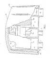
- the apparatus is constructed predominently, preferably, from plastics materials and the reservoir 1 may be of moulded or fabricated rigid plastics materials with a cylindrical upright wall part 2 and a horizontal substantially flat base 3 through which the water inlet and water outlet connections, 4 and 5, extend.
- the water inlet connection 4 is centrally disposed and extends co-axially into an inner upright tubular part 6 within the reservoir 1 to have an upper screw-threaded end portion 6a with which a complementary screw-threaded lower boss or collar portion 7a of a main valve body 7 of the equalising valve part (generally indicated by the arrow 8) can be engaged to locate the equalising valve assembly 8 co-axially of the unit.
- the valve body 7 is also cylindrical (either for its full length or of stepped cylindrical form, as shown with the upper part of larger diameter) and the float member 9 may be in the form of an inverted cup located as a relatively close fit over the cylindrical valve assembly 7 and 8 and within the cylindrical reservoir wall 2.
- the float member 9 can be manufactured from such as a high density polyurethene foam material so as to have a thick outer wall 9a forming the main body of the float member 9, and a transverse upper wall 9b the lower side of which is arranged to contact and move a pressure relief valve 10 of the equalising valve assembly 8 when the float member 9 moves towards its lower level on water draw off from the reservoir 1; and the upper side of which float member 9 is preferably provided with a recess 9c or plurality of recesses 9c so that weight members such as lead weight members 10 can be inserted therein for weighting of the float member 9 and adjustment of pressure balance according to the pressure of the water at the water inlet 4.
- the weight recess or recesses 9c can be of annular form to provide a central upstand 9d to the float member 9 facilitating gripping with the fingers of a person assembling, installing or servicing the system.
- Wall 9b has at least one vent 9e.
- the assembly is preferably provided also with a cover 12 which can be manufactured of such as a polyurethene foam for thermal insulation purposes, and it may be further coated with a protective coating such as rubberised coating e.g. a Monolar (Registered Trade Mark) rubberised coating to prevent the polyurethene (or polystyrene) plastics cover 12 from breaking down in adverse weather conditions.
- the reservoir 1 is also provided with an overflow outlet 13 opening to the upper end thereof and such overflow outlet 13 may be connected to a conduit 13a separately formed and attached to the reservoir 1 or formed in the moulding thereof so that overflow water, in the event of the equalising valve assembly cut-off arrangement not operating correctly, may be directed to waste or to an overflow tray or receiving drain, or returned to a supply source.
- the cover 12 may have a shaped extension part 12a to extend around and over the conduit part 13a.
- the base 3 of the reservoir 1 may extend beyond the cylindrical wall 2 to provide an annular flange 14 which can be provided with a plurality of spaced apertures 14a to enable fixing of the reservoir 1 and system as a whole to any supporting bracket or other fixture or structure (not shown) ; and the cover 12 may have its lower peripheral edge portion 12b recessed to accommodate the flange 14 in maintaining the cover 12 as a relatively close fit over the reservoir 1 and flange 14 for good insulation and to prevent leaves and dirt etc. entering the reservoir from outside.
- Unemployed flange holes 14a provide access for air to the cover and upper side of the reservoir and prevent suction hampering water flow from the unit via outlet 5.
- the reservoir 1 may be in the region of only 200 to 300 millimetres in diameter and 100 to 200 millimetres in height, with the arrangement of the float member 9 and equalising valve assembly 8 providing for a normal maximum water height of approximately one-half the height of the reservoir 1 and a water fall of not more than 25 to 30 millimetres before the equalising valve assembly 8 reaches the fully open position for maximum inflow of water, but the arrangement is such that the equalising valve assembly is re-actuated and progressively opened to permit ingress of the higher pressure water as soon as water is drawn off and the float-member 9 commences to fall, e.g. a 1mm fall will permit initial ingress of water.
- the inlet connection 4 may be for 14 millimetre or 19 millimetre inside diameter pipe supplying the higher pressure water, and the outlet connection 4 for water draw-off may be for 25 millimetre inside diameter pipe.
- the float member 9 and equalising valve assembly 6 are arranged and dimensioned to occupy a major portion of the total capacity of the reservoir 1 e.g. in excess of two-thirds, and thus a very compact assembly is provided.
- the collector unit (as exampled at 'S' in figure 10 is located on the roof of a building and may be in relatively close proximity to the main hot water header tank in the roof, and it is frequently a requirement that there be either a tall stand pipe or header pipe 15, or a further header tank 16 (as indicated in broken outline in figure 10)for the system and which, as will be appreciated, may be unslightly and will require the addition of a covering and a very strong supporting structure 17.
- the water pressure conversion unit generally indicated at 1 ⁇ may sit neatly and unobtrusively adjacent the solar water system 'S',coupled in line therewith.
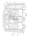
- the most important part of the present invention involves the construction and operation of the equalising valve assembly 8 and reference is now made particularly to figures 3 to 9 inclusive for a more detailed description of the preferred aspects of the present invention.
- Simple diaphgram shut -off valves are commonly provided to prevent and restrict such as water flow, with a flexible diaphragm member closing on or opening away from one or more water flow openings, according to pressure either side of the valve.
- the present invention goes further by employing a diaphragm type of valve arrangement incorporating bleed means to initiate action and further providing for progressive individual opening and closing of water passages to stabilise water pressure and more positively regulate flow to eliminate or substantially alleviate water hammer, such as frequently occurs in high pressure water and fluctuating pressure water systems.
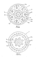
- valve body 7 (shown particularly in figures 3,4 and 5) has an upper transverse wall part 7b from which the outer cylindrical boss or collar part 7a depends for screw-threaded engagement with the tubular inlet upstand 6 of the reservoir 1, and a central co-axial part 7c depends from the transverse part 7b to form an annular space 18 between such depending central part 7c and the collar part 7a and tubular upstand upper portion 6a for the inflow of the higher pressure water to the equalising valve assembly 8.
- an annular disc-like filter and flow diffuser member 19 is mounted at the lower end of the valve body 7 within the upper part 6a of the tubular upstand 6 to prevent extraneous matter in the water inlet supply entering the equalising valve assembly 8 and to further diffuse the high pressure flow of incoming water and facilitate the smooth operation of the equalising valve assembly 8.
- the filter diffuser member 19 may take various forms and can for example be of a simple metal mesh form or the filter diffuser member 19 can be specially fabricated e.g.
- the upper transverse part 7b of the valve body 7 is of larger diameter than the lower tubular collar part 7a so as to project laterally therefrom, and the upper side of the valve body transverse part 7b is provided with a plurality of equally spaced substantially circular recesses 20 located on the same concentric axis near,but to the inner side of,the junction between the tubular collar part 7a and the transverse part 7b; each such recess 20 being provided with a co-axial bore 21 opening to the inner side of the tubular collar part 7a and thus to incoming water under higher pressure in the tubular upstand 6 of the inlet 4, and at least one but preferably a plurality (e.g.
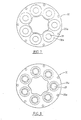
- valve seats 21a within the recesses 20 which are capable of being closed individually by valve parts 23a of a unitary diaphragm valve assembly 23 (see figures 3 and 6) which is clamped in position between the valve body transverse part 7a and an upper capping part 24 (see figures 3 and 9), such as by securing screws 25 located in aligned holes 25a of the capping and body parts, with the holes 25a in the body part transverse part 7b being screw-threaded to receive such screws 25.
- the diaphragm valve assembly 23 comprises a circular (in plan) member constructed primarily of a natural or synthetic rubber material and preferably pre-shaped with a plurality of frusto-conical parts 23a dimensioned and positioned so as to locate over and project downwardly into each of the recesses 20 of the valve body transverse part 7b, and arranged so that the lower end portions of each such depending frusto-conical parts 23a has a thickened depending cylindrical valve part 23b capable of engaging and sealing on the respective valve seat 21a, which may be in the form of an inner annular upstanding lip 21a, of each recess 20.
- each such central depending valve part 23b of the diaphragm concial parts 23a is provided with a fine bleed means for the purpose hereinafter described, and in one preferred form of the invention and as illustrated each such diaphragm valve part 23b is fitted with a nipple insert 26 of a hard plastics material such as a nylon and which may have a depending co-axial conical head 26a projecting into the respective co-axial bore (facilitating correct location of the respective diaphragm valve part 23b on its seat and reinforcing such valve part 23 against distortion to lessen the risk of leakage), and a fine co-axial bleed bore 27 extends fully through such reinforcing diaphragm nipple 26 to provide communication between the inner side of the valve body tubular collar part 7a and the upper side of the diaphragm frusto-conical part below the capping part 24.
- a nipple insert 26 of a hard plastics material such as a nylon and which may have a depending co-axial con
- the capping part 24 is provided on its underside with a plurality of recesses 28 complementary to and alignable with the recesses 20 of the body transverse part 7b and the frusto-conical diaphragm valve parts 23a; and each such capping part recess 28 is provided with a co-axial depending abutment 29 against which the upper central portion of the diaphragm valve frusto-conical part 23a and the upper end of the nipple insert 26 can abut to restrict upward movement thereof whilst permitting water and/or air flow in the annulus formed about such central depending abutment 29 within each capping part recess 28.
- the depending abutment 29 may be provided with a medial transverse open-ended slot 29a which aligns with the bleed bore 27 of the nipple insert 26 so that liquid or air flow therethrough is not restricted at any time.
- an intermediate diaphragm support plate 30 in the form of an annular disc like member which locates within a concentric annular recess 7d in the upper side of the valve body transverse part 7b over the individual valve recesses 20; and such support plate 30 is provided with a plurality of equally spaced apertures 31 positioned on a concentric pitch circle and corresponding in number to the number of valve apertures 21 and recesses 20; and each of a diameter such that the respective depending cylindrical valve parts 23b of the diaphragm member 23 can slidably locate therein and be maintained in the correct position on its respective valve seat or lip 21a.
- the upper side of the support plate 30 may be provided with a conical recess 30a at each such guide aperture 31 and conforming to the normal configuration of the frusto-conical diaphragm part 23a engageable therewith; and part cylindrical gapped projections 31a may extend below the guide apertures 31 as extensions thereof in supporting the respective diaphragm cylindrical valve parts 23b through the major part of their movement and onto the respective valve seats or lips 21a without restricting water flow through the inlet and outlet apertures 21 and 22 of the valve recesses 20 in the valve body transverse part 7b when the diaphragm valve parts 23b are open.
- the body capping part 24 can be provided on its underside with a uniform height continuous small projecting rib 24a which will press tightly into the diaphragm 23 when sandwiched between the body 7, support plate 30 and capping part 24.
- the equalising valve assembly 8 further includes an actuating pressure relief valve and flow regulating assembly 10 comprising a vertically and co-axially disposed needle valve having a stem 32 located in a clearance co-axial bore 33 of a cylindrical piston member 34 for limited vertical movement within such piston member 34; the piston member 34 being in turn slidably located and sealed within a co-axial cylindrical tube piston sleeve 35 mounted within a co-axial bore 36 the body central part 7c and depending downwardly therefrom into the inlet tubular upstand 6 of the complete assembly.
- an actuating pressure relief valve and flow regulating assembly 10 comprising a vertically and co-axially disposed needle valve having a stem 32 located in a clearance co-axial bore 33 of a cylindrical piston member 34 for limited vertical movement within such piston member 34; the piston member 34 being in turn slidably located and sealed within a co-axial cylindrical tube piston sleeve 35 mounted within a co-axial bore 36 the body central part 7c and depending downwardly therefrom into the inlet tubular upstand 6 of
- the bore 36 of the valve body 7 in which the piston sleeve 35 is located is provided with a plurality of parallel vertically and longitudinally positioned channels 37 corresponding to the number of diaphragm valves 23a,23b and recesses 20,28; with such channels 37 being closed at their lower end and opening at the upper end for communication with aligned apertures and channels 38 in the body capping part 24 which in turn provide communication with the respective body capping part recesses 28 to the upper side of the diaphragm frusto-conical valve parts 23a.
- the piston sleeve 35 is provided along its length with a plurality spaced of small flow control apertures 39 corresponding in number to and aligned with the longitudinal channels 37 within the valve body 7 and within the confines of the piston member 34 when in its uppermost position.
- the piston member 34 is an elongate member with upper and lower seal rings 34a positioned such that in the normal uppermost position indicated the flow control apertures 39 in the piston sleeve 35 are located between the seals 34a to prevent the passage of air therethrough; and when in the lowest position when the reservoir 1 is empty or near empty and the float member 9 at its lowest position causing the needle valve assembly 10 to be moved to its lowest position, the piston sleeve flow control apertures 39 will be open to atmosphere.
- the needle valve has its needle stem 32 extending longitudinally through the piston member 34 as aforesaid to have a valve member 40 located at the lower end of the piston member 34 and capable of sealing against a valve seat or such as an O-ring seal 41 about the needle bore 33 of the piston member 34.
- the lower end part 32a of the needle stem 32 may project downwardly and through a clearance aperture 42 in an otherwise closed lower end 35a of the piston sleeve 35 (the diameter of such aperture permitting water under pressure to bleed therethrough but being fine enough to prevent the passage of unwanted extraneous matter or dirt particles).
- An enlarged pin or start-cap extension 43 projects upwardly from the upper end of the needle stem 32 above the piston member 34 and through central clearance apertures in the diaphragm 23 and valve body capping part 24, so that its upper end can freely abut the inner under side of the float member recess 9d whereby the float member 9 is free to move upwardly on filling the reservoir 1 with water and at the same time is arranged to engage the start pin or cap 43 of the needle valve to move the needle valve assembly 10 downwardly on any water draw-off and lowering of the float member 9 below the prescribed level.
- the arrangement is such that there need only be a small gap e.g.
- the initial water pressure will raise the needle valve 40 to close on the seat or seal 41 at the lower end of the piston 34 and seal off the needle bore 33 of the piston member 34; and thereupon the water under pressure will acton the lower side of the needle valve piston member 34 to urge the needle valve assembly 10 upwardly so as to rise with the rising of the float member 9 as the reservoir 1 is filled, the upper end of the needle start pin or cap 43 abuting the underside of the float member 9 within its recess 9d.
- the piston sleeve flow control apertures 39 are progressively sealed off, and at the same time there is a slight bleed of water under pressure through the bleed bores 27 of the diaphragm valve insert nipples 26 into the recesses 28 above the frusto-conical diaphragm valve parts 23a and within the valve member capping part 24.
- the float member 9 When low pressure water is drawn off through the outlet 5 of the reservoir 1, the float member 9 will accordingly commence to lower and on contacting the upper end of the needle start pin or cap 43 (there can be a small gap between the float member and needle start pin or cap to allow "lost time” and for water evaporation etc.
- the needle valve 40 will be opened initially (as mentioned this can be within one millimetre of downward movement of the needle valve assembly 10) to allow water under pressure to pass through the needle bore 33 of the piston member 34 to the upper side of the diaphragm valve parts 23a,23b via the connecting channels 37,38 and recesses 28 (in the illustrated form of the invention the central part of the diaphragm assembly 23 is of frusto-conical form and locates over the upper end of the piston sleeve 25 and between the central parts of the valve body 7 and valve body capping part 24, and accordingly appropriate communicating apertures 44 can be provided in the diaphragm member communicating with the respective channels 37,38 and recesses 28).
- the flow control or regulating apertures 39 in the piston sleeve 35 are equally spaced circumferentially but at different levels longitudinally of the piston sleeve 35 so that as the piston 34 slides downwardly with the needle valve assembly 10 and within the piston sleeve 35, the flow control apertures 39 are gradually uncovered in sequence so that initially, when the uppermost aperture 39 is exposed from sealing by the piston member 34, the water in the capping part recess 28 at the upper side of the first diaphragm frusto-conical and valve parts 23a,23b becomes exposed to normal air pressure through the central aperture 24b of the capping member 24 thus relieving the pressure on such upper side and enabling water pressure from within the tubular upstand 6 to exert force on the under surface of the valve insert nipple 26 and valve part 23b of the diaphragm 23 to permit water under pressure to pass through the communicating openings into the reservoir 1 for first trickle filling.
- the needle valve assembly 10 With greater water draw-off the needle valve assembly 10 will continue to lower and the piston 34 will sequentially expose more of the flow control apertures 39 to atmosphere for progressive opening of the series of valve parts 23b to increase water flow into the reservoir 1 and so that with full outlet flow and lowering of the water level to its lowest point all the diaphragm valve parts 23b will be off their respective seats 21a enabling full inlet water under pressure to be fed into the reservoir 1 causing the float member 9 and needle valve assembly 10 to rise and progressively close off the flow control apertures 39 for smooth operation of the system.
- the flow control apertures 39 can be positioned in a spiral manner about the piston sleeve 35 so that the respective diaphragm valve parts 23b are opened in direct adjacent series, preferably the arrangement provides for staggered formation of the flow control apertures for staggered opening and closing of the diaphragm valve parts 23b e.g. if for example there are, as illustrated, seven individual diaphragm frusto-conical and valve parts 23a,23b in the diaphragm valve assembly 23, with equivalent numbers of flow control apertures 39 and connecting channels 37 etc., and the valve parts 23b are number 1 to 7 in series, the opening or closing sequence could be 1,5,2,6,3,7, 4, or some other suitable staggered sequence.
- control of the water flow and valve actuation may be achieved by having different diameters for the co-axial inlet bores 21 for the respective valve recesses 20 in the body part 7 e.g. the diameters of such bores 21 may progressively increase equally in series, or in staggered relationship.
- the system is not confined to one having the illustrated seven individual water passage and valve arrangement, but any number can be provided and may be preferred according to the required size and capacity of the system. Whilst the system may perform reasonably well in some situations with only 2, 3 or 4 water passage and valve arrangements, a higher number (e.g. 5, 6, 7 or 8) will generally provide for smoother more effective operation.
- an improved and compact pressure adjusting system enabling water under high or uneven pressure at an inlet source to be converted to a substantially constant low pressure supply at the outlet 5; the arrangement providing that the reservoir contains a relatively small amount of water, and discharge through the outlet 5 of a small amount of water effects the required amount of float movement for actuation of the equalising valve assembly 8 so that there is a continual trickle or frequent intermittent supply of high pressure water providing a constant supply of substantially constant low pressure outgoing water.
- the use of the invention is not confined to solar water systems, but may have many other applications. It is envisaged for example that the invention may be particularly usefully employed in high rise building situations such as in large hotel, condominium and flat complexes served by main roof-top water header tank systems; in such complexes and systems,water supply pressures at the different floor levels will normally vary according to their height and relativity to the header tank system concerned, and vary at the individual units of the complexes with water draw-off at other units. Accordingly, a single water supply system of the present invention can be installed at the various floor levels for supply of water to all or group of units on the respective floors, and/or individual supply systems can be provided for the units of a complex. As previously indicated the system of this invention is not restricted to any particular size and the water pressure at the outlet side of the system can be readily varied accordingly to a users requirements such as by internal port and water passage size variation and the employment of interchangeable parts.
Landscapes
- Engineering & Computer Science (AREA)
- General Engineering & Computer Science (AREA)
- Physics & Mathematics (AREA)
- Mechanical Engineering (AREA)
- Fluid Mechanics (AREA)
- General Physics & Mathematics (AREA)
- Automation & Control Theory (AREA)
- Self-Closing Valves And Venting Or Aerating Valves (AREA)
- Fluid-Driven Valves (AREA)
- Float Valves (AREA)
Applications Claiming Priority (1)
| Application Number | Priority Date | Filing Date | Title |
|---|---|---|---|
| NZ209937A NZ209937A (en) | 1984-10-19 | 1984-10-19 | Multiple chamber valve: biassed closed member in each chamber overcome by pressure differential |
Publications (1)
| Publication Number | Publication Date |
|---|---|
| EP0236608A1 true EP0236608A1 (fr) | 1987-09-16 |
Family
ID=19920949
Family Applications (1)
| Application Number | Title | Priority Date | Filing Date |
|---|---|---|---|
| EP86301746A Ceased EP0236608A1 (fr) | 1984-10-19 | 1986-03-11 | Système de distribution d'eau |
Country Status (8)
| Country | Link |
|---|---|
| US (1) | US4671317A (fr) |
| EP (1) | EP0236608A1 (fr) |
| JP (1) | JPS61102923A (fr) |
| CN (1) | CN1006324B (fr) |
| AU (1) | AU573392B2 (fr) |
| GB (1) | GB2165967B (fr) |
| IN (1) | IN165937B (fr) |
| NZ (1) | NZ209937A (fr) |
Cited By (1)
| Publication number | Priority date | Publication date | Assignee | Title |
|---|---|---|---|---|
| CN102141311A (zh) * | 2011-03-21 | 2011-08-03 | 王国卿 | 太阳能热水器防冻装置 |
Families Citing this family (5)
| Publication number | Priority date | Publication date | Assignee | Title |
|---|---|---|---|---|
| US5832953A (en) * | 1996-02-20 | 1998-11-10 | Lattner; Michael D. | Overfill shut-off system for liquid storage tanks |
| US6883780B2 (en) * | 1998-10-09 | 2005-04-26 | Swagelok Company | Sanitary diaphragm valve |
| US6394417B1 (en) | 1998-10-09 | 2002-05-28 | Swagelok Co. | Sanitary diaphragm valve |
| CN1309912C (zh) * | 2003-06-18 | 2007-04-11 | 刘德周 | 节水型单管网小区分质供水装置 |
| CN110657259B (zh) * | 2019-10-10 | 2021-11-19 | 宁波方太厨具有限公司 | 旁通流量阀及包含其的燃气热水器 |
Citations (2)
| Publication number | Priority date | Publication date | Assignee | Title |
|---|---|---|---|---|
| US3856046A (en) * | 1972-10-17 | 1974-12-24 | Tool Instr Ass Inc | Valve |
| US4352371A (en) * | 1980-03-10 | 1982-10-05 | Walters William R | Low-high flow rate valve |
Family Cites Families (7)
| Publication number | Priority date | Publication date | Assignee | Title |
|---|---|---|---|---|
| US174420A (en) * | 1876-03-07 | Improvement in automatic tank-fillers | ||
| US527346A (en) * | 1894-10-09 | Thomas j | ||
| GB302756A (en) * | 1927-10-15 | 1928-12-27 | Walter Smith | Improvements in apparatus for controlling the flow of liquids to maintain a constantlevel |
| US2619122A (en) * | 1947-02-20 | 1952-11-25 | Rutherford H Hunter | Flow regulator and float valve assembly |
| AU485149B2 (en) * | 1969-05-23 | 1971-12-02 | Herman Werner Fritz | Fluid valve and ball cock incorporating same |
| AU1991576A (en) * | 1976-11-23 | 1978-06-01 | Brandelli A R | Toilet bowl valve |
| US4173255A (en) * | 1978-10-05 | 1979-11-06 | Kramer Richard W | Low well yield control system and method |
-
1984
- 1984-10-19 NZ NZ209937A patent/NZ209937A/xx unknown
-
1985
- 1985-10-07 AU AU48410/85A patent/AU573392B2/en not_active Ceased
- 1985-10-09 GB GB08524873A patent/GB2165967B/en not_active Expired
- 1985-10-11 CN CN85108427A patent/CN1006324B/zh not_active Expired
- 1985-10-18 JP JP60233112A patent/JPS61102923A/ja active Pending
-
1986
- 1986-03-11 EP EP86301746A patent/EP0236608A1/fr not_active Ceased
- 1986-03-20 US US06/841,834 patent/US4671317A/en not_active Expired - Fee Related
- 1986-03-31 IN IN298/DEL/86A patent/IN165937B/en unknown
Patent Citations (2)
| Publication number | Priority date | Publication date | Assignee | Title |
|---|---|---|---|---|
| US3856046A (en) * | 1972-10-17 | 1974-12-24 | Tool Instr Ass Inc | Valve |
| US4352371A (en) * | 1980-03-10 | 1982-10-05 | Walters William R | Low-high flow rate valve |
Cited By (1)
| Publication number | Priority date | Publication date | Assignee | Title |
|---|---|---|---|---|
| CN102141311A (zh) * | 2011-03-21 | 2011-08-03 | 王国卿 | 太阳能热水器防冻装置 |
Also Published As
| Publication number | Publication date |
|---|---|
| US4671317A (en) | 1987-06-09 |
| GB8524873D0 (en) | 1985-11-13 |
| CN85108427A (zh) | 1986-05-10 |
| GB2165967B (en) | 1988-09-01 |
| JPS61102923A (ja) | 1986-05-21 |
| GB2165967A (en) | 1986-04-23 |
| IN165937B (fr) | 1990-02-10 |
| AU4841085A (en) | 1986-04-24 |
| NZ209937A (en) | 1989-05-29 |
| CN1006324B (zh) | 1990-01-03 |
| AU573392B2 (en) | 1988-06-09 |
Similar Documents
| Publication | Publication Date | Title |
|---|---|---|
| JP3655318B2 (ja) | 調節可能な注入弁組立体 | |
| AU592701B2 (en) | Adjustable vacuum breaker fill valve | |
| EP0100657A1 (fr) | Soupape d'admission d'air | |
| US6510866B2 (en) | Ball cock assembly, float assembly for same, and method of controlling liquid level in a tank | |
| US6779544B2 (en) | Tank refueling shutoff valve and vent system | |
| CN1133909C (zh) | 弹性元件阀 | |
| US3693649A (en) | Water control for toilet tanks | |
| EP0236608A1 (fr) | Système de distribution d'eau | |
| US6047725A (en) | Adjustable height fill valve | |
| US5123125A (en) | Flushing tank for use with toilet bowls | |
| WO1994004971A1 (fr) | Dispositif pour controler le niveau d'un liquide | |
| US5309937A (en) | Float valve for filling systems, in particular, for filling electric traction batteries | |
| US4749633A (en) | Battery watering device | |
| US3584644A (en) | Toilet tank supply valve assembly | |
| US4186765A (en) | Liquid level control valve assembly | |
| US4286619A (en) | Ballcock assembly | |
| CA1266220A (fr) | Systemes d'alimentation en eau | |
| KR101175926B1 (ko) | 상시개방형 증기배출밸브 | |
| US2667177A (en) | Flush tank valve with vacuum breaker | |
| US3550651A (en) | Improvements in topping-up devices for electric batteries | |
| CN212177885U (zh) | 一种自动排水阀 | |
| US3785394A (en) | Water control valve structure | |
| WO2000019135A1 (fr) | Soupape d'aspiration pour citernes | |
| CN111550561B (zh) | 一种自动排水阀 | |
| SU901703A1 (ru) | Вантуз |
Legal Events
| Date | Code | Title | Description |
|---|---|---|---|
| PUAI | Public reference made under article 153(3) epc to a published international application that has entered the european phase |
Free format text: ORIGINAL CODE: 0009012 |
|
| AK | Designated contracting states |
Kind code of ref document: A1 Designated state(s): AT BE CH DE FR IT LI LU NL SE |
|
| 17P | Request for examination filed |
Effective date: 19880309 |
|
| 17Q | First examination report despatched |
Effective date: 19890223 |
|
| STAA | Information on the status of an ep patent application or granted ep patent |
Free format text: STATUS: THE APPLICATION HAS BEEN REFUSED |
|
| 18R | Application refused |
Effective date: 19900519 |