EP0236609B1 - Verfahren und Vorrichtung für das gleichzeitige Regenerieren und Kühlen von fluidizierten Teilchen - Google Patents
Verfahren und Vorrichtung für das gleichzeitige Regenerieren und Kühlen von fluidizierten Teilchen Download PDFInfo
- Publication number
- EP0236609B1 EP0236609B1 EP86301760A EP86301760A EP0236609B1 EP 0236609 B1 EP0236609 B1 EP 0236609B1 EP 86301760 A EP86301760 A EP 86301760A EP 86301760 A EP86301760 A EP 86301760A EP 0236609 B1 EP0236609 B1 EP 0236609B1
- Authority
- EP
- European Patent Office
- Prior art keywords
- particle
- catalyst
- zone
- combustion
- particles
- Prior art date
- Legal status (The legal status is an assumption and is not a legal conclusion. Google has not performed a legal analysis and makes no representation as to the accuracy of the status listed.)
- Expired
Links
- 238000001816 cooling Methods 0.000 title claims abstract description 132
- 239000002245 particle Substances 0.000 title claims abstract description 130
- 238000000034 method Methods 0.000 title claims description 32
- 230000008569 process Effects 0.000 title claims description 23
- 230000001172 regenerating effect Effects 0.000 title description 3
- 239000003054 catalyst Substances 0.000 claims abstract description 180
- 238000002485 combustion reaction Methods 0.000 claims abstract description 85
- 239000007787 solid Substances 0.000 claims abstract description 25
- 238000012546 transfer Methods 0.000 claims abstract description 23
- 239000000567 combustion gas Substances 0.000 claims abstract description 17
- 239000007789 gas Substances 0.000 claims description 61
- 239000000463 material Substances 0.000 claims description 25
- QVGXLLKOCUKJST-UHFFFAOYSA-N atomic oxygen Chemical compound [O] QVGXLLKOCUKJST-UHFFFAOYSA-N 0.000 claims description 8
- 229910052760 oxygen Inorganic materials 0.000 claims description 8
- 239000001301 oxygen Substances 0.000 claims description 8
- 230000001105 regulatory effect Effects 0.000 claims description 8
- 238000004891 communication Methods 0.000 claims description 5
- 230000003647 oxidation Effects 0.000 claims description 5
- 238000007254 oxidation reaction Methods 0.000 claims description 5
- 238000005243 fluidization Methods 0.000 claims description 4
- 230000004044 response Effects 0.000 claims description 3
- 230000001590 oxidative effect Effects 0.000 claims description 2
- 230000008929 regeneration Effects 0.000 abstract description 19
- 238000011069 regeneration method Methods 0.000 abstract description 19
- 238000007599 discharging Methods 0.000 abstract 1
- 239000000571 coke Substances 0.000 description 24
- 238000006243 chemical reaction Methods 0.000 description 18
- 239000003546 flue gas Substances 0.000 description 11
- UGFAIRIUMAVXCW-UHFFFAOYSA-N Carbon monoxide Chemical compound [O+]#[C-] UGFAIRIUMAVXCW-UHFFFAOYSA-N 0.000 description 10
- 238000012545 processing Methods 0.000 description 9
- 239000012530 fluid Substances 0.000 description 8
- 239000000203 mixture Substances 0.000 description 7
- 239000003921 oil Substances 0.000 description 6
- OKTJSMMVPCPJKN-UHFFFAOYSA-N Carbon Chemical compound [C] OKTJSMMVPCPJKN-UHFFFAOYSA-N 0.000 description 5
- 229910052799 carbon Inorganic materials 0.000 description 5
- 239000002826 coolant Substances 0.000 description 5
- 230000000694 effects Effects 0.000 description 5
- 239000000047 product Substances 0.000 description 5
- 238000000926 separation method Methods 0.000 description 5
- XLYOFNOQVPJJNP-UHFFFAOYSA-N water Substances O XLYOFNOQVPJJNP-UHFFFAOYSA-N 0.000 description 5
- 238000005336 cracking Methods 0.000 description 4
- 230000003197 catalytic effect Effects 0.000 description 3
- 239000001257 hydrogen Substances 0.000 description 3
- 229910052739 hydrogen Inorganic materials 0.000 description 3
- 238000002156 mixing Methods 0.000 description 3
- IJGRMHOSHXDMSA-UHFFFAOYSA-N Atomic nitrogen Chemical compound N#N IJGRMHOSHXDMSA-UHFFFAOYSA-N 0.000 description 2
- IMNFDUFMRHMDMM-UHFFFAOYSA-N N-Heptane Chemical compound CCCCCCC IMNFDUFMRHMDMM-UHFFFAOYSA-N 0.000 description 2
- NINIDFKCEFEMDL-UHFFFAOYSA-N Sulfur Chemical compound [S] NINIDFKCEFEMDL-UHFFFAOYSA-N 0.000 description 2
- 230000008859 change Effects 0.000 description 2
- 230000001276 controlling effect Effects 0.000 description 2
- 230000008021 deposition Effects 0.000 description 2
- 238000009826 distribution Methods 0.000 description 2
- 150000002431 hydrogen Chemical class 0.000 description 2
- 239000007788 liquid Substances 0.000 description 2
- 238000011068 loading method Methods 0.000 description 2
- 238000011084 recovery Methods 0.000 description 2
- 230000009467 reduction Effects 0.000 description 2
- 230000000717 retained effect Effects 0.000 description 2
- 229910052717 sulfur Inorganic materials 0.000 description 2
- 239000011593 sulfur Substances 0.000 description 2
- UFHFLCQGNIYNRP-UHFFFAOYSA-N Hydrogen Chemical compound [H][H] UFHFLCQGNIYNRP-UHFFFAOYSA-N 0.000 description 1
- 230000008901 benefit Effects 0.000 description 1
- 238000009835 boiling Methods 0.000 description 1
- 239000006227 byproduct Substances 0.000 description 1
- 238000003889 chemical engineering Methods 0.000 description 1
- 238000010276 construction Methods 0.000 description 1
- 230000008602 contraction Effects 0.000 description 1
- 239000000498 cooling water Substances 0.000 description 1
- 239000010779 crude oil Substances 0.000 description 1
- 230000001627 detrimental effect Effects 0.000 description 1
- 230000009977 dual effect Effects 0.000 description 1
- 238000005516 engineering process Methods 0.000 description 1
- 230000003628 erosive effect Effects 0.000 description 1
- 238000011049 filling Methods 0.000 description 1
- 238000004231 fluid catalytic cracking Methods 0.000 description 1
- 239000000295 fuel oil Substances 0.000 description 1
- 230000005484 gravity Effects 0.000 description 1
- 239000010763 heavy fuel oil Substances 0.000 description 1
- 238000007654 immersion Methods 0.000 description 1
- 230000004941 influx Effects 0.000 description 1
- 238000005272 metallurgy Methods 0.000 description 1
- 229910052757 nitrogen Inorganic materials 0.000 description 1
- 238000013021 overheating Methods 0.000 description 1
- JTJMJGYZQZDUJJ-UHFFFAOYSA-N phencyclidine Chemical class C1CCCCN1C1(C=2C=CC=CC=2)CCCCC1 JTJMJGYZQZDUJJ-UHFFFAOYSA-N 0.000 description 1
- 239000011369 resultant mixture Substances 0.000 description 1
- 230000000630 rising effect Effects 0.000 description 1
- 230000009528 severe injury Effects 0.000 description 1
- 239000011343 solid material Substances 0.000 description 1
- 239000000126 substance Substances 0.000 description 1
- -1 sulfur Chemical class 0.000 description 1
Images

Classifications
-
- B—PERFORMING OPERATIONS; TRANSPORTING
- B01—PHYSICAL OR CHEMICAL PROCESSES OR APPARATUS IN GENERAL
- B01J—CHEMICAL OR PHYSICAL PROCESSES, e.g. CATALYSIS OR COLLOID CHEMISTRY; THEIR RELEVANT APPARATUS
- B01J8/00—Chemical or physical processes in general, conducted in the presence of fluids and solid particles; Apparatus for such processes
- B01J8/18—Chemical or physical processes in general, conducted in the presence of fluids and solid particles; Apparatus for such processes with fluidised particles
- B01J8/1809—Controlling processes
-
- C—CHEMISTRY; METALLURGY
- C10—PETROLEUM, GAS OR COKE INDUSTRIES; TECHNICAL GASES CONTAINING CARBON MONOXIDE; FUELS; LUBRICANTS; PEAT
- C10G—CRACKING HYDROCARBON OILS; PRODUCTION OF LIQUID HYDROCARBON MIXTURES, e.g. BY DESTRUCTIVE HYDROGENATION, OLIGOMERISATION, POLYMERISATION; RECOVERY OF HYDROCARBON OILS FROM OIL-SHALE, OIL-SAND, OR GASES; REFINING MIXTURES MAINLY CONSISTING OF HYDROCARBONS; REFORMING OF NAPHTHA; MINERAL WAXES
- C10G11/00—Catalytic cracking, in the absence of hydrogen, of hydrocarbon oils
- C10G11/14—Catalytic cracking, in the absence of hydrogen, of hydrocarbon oils with preheated moving solid catalysts
- C10G11/18—Catalytic cracking, in the absence of hydrogen, of hydrocarbon oils with preheated moving solid catalysts according to the "fluidised-bed" technique
- C10G11/182—Regeneration
-
- C—CHEMISTRY; METALLURGY
- C10—PETROLEUM, GAS OR COKE INDUSTRIES; TECHNICAL GASES CONTAINING CARBON MONOXIDE; FUELS; LUBRICANTS; PEAT
- C10G—CRACKING HYDROCARBON OILS; PRODUCTION OF LIQUID HYDROCARBON MIXTURES, e.g. BY DESTRUCTIVE HYDROGENATION, OLIGOMERISATION, POLYMERISATION; RECOVERY OF HYDROCARBON OILS FROM OIL-SHALE, OIL-SAND, OR GASES; REFINING MIXTURES MAINLY CONSISTING OF HYDROCARBONS; REFORMING OF NAPHTHA; MINERAL WAXES
- C10G11/00—Catalytic cracking, in the absence of hydrogen, of hydrocarbon oils
- C10G11/14—Catalytic cracking, in the absence of hydrogen, of hydrocarbon oils with preheated moving solid catalysts
- C10G11/18—Catalytic cracking, in the absence of hydrogen, of hydrocarbon oils with preheated moving solid catalysts according to the "fluidised-bed" technique
- C10G11/187—Controlling or regulating
-
- B—PERFORMING OPERATIONS; TRANSPORTING
- B01—PHYSICAL OR CHEMICAL PROCESSES OR APPARATUS IN GENERAL
- B01J—CHEMICAL OR PHYSICAL PROCESSES, e.g. CATALYSIS OR COLLOID CHEMISTRY; THEIR RELEVANT APPARATUS
- B01J2208/00—Processes carried out in the presence of solid particles; Reactors therefor
- B01J2208/00008—Controlling the process
- B01J2208/00017—Controlling the temperature
- B01J2208/00106—Controlling the temperature by indirect heat exchange
- B01J2208/00168—Controlling the temperature by indirect heat exchange with heat exchange elements outside the bed of solid particles
- B01J2208/00203—Coils
-
- B—PERFORMING OPERATIONS; TRANSPORTING
- B01—PHYSICAL OR CHEMICAL PROCESSES OR APPARATUS IN GENERAL
- B01J—CHEMICAL OR PHYSICAL PROCESSES, e.g. CATALYSIS OR COLLOID CHEMISTRY; THEIR RELEVANT APPARATUS
- B01J2208/00—Processes carried out in the presence of solid particles; Reactors therefor
- B01J2208/00008—Controlling the process
- B01J2208/00017—Controlling the temperature
- B01J2208/00106—Controlling the temperature by indirect heat exchange
- B01J2208/00168—Controlling the temperature by indirect heat exchange with heat exchange elements outside the bed of solid particles
- B01J2208/00256—Controlling the temperature by indirect heat exchange with heat exchange elements outside the bed of solid particles in a heat exchanger for the heat exchange medium separate from the reactor
-
- B—PERFORMING OPERATIONS; TRANSPORTING
- B01—PHYSICAL OR CHEMICAL PROCESSES OR APPARATUS IN GENERAL
- B01J—CHEMICAL OR PHYSICAL PROCESSES, e.g. CATALYSIS OR COLLOID CHEMISTRY; THEIR RELEVANT APPARATUS
- B01J2208/00—Processes carried out in the presence of solid particles; Reactors therefor
- B01J2208/00008—Controlling the process
- B01J2208/00017—Controlling the temperature
- B01J2208/00106—Controlling the temperature by indirect heat exchange
- B01J2208/00265—Part of all of the reactants being heated or cooled outside the reactor while recycling
- B01J2208/00292—Part of all of the reactants being heated or cooled outside the reactor while recycling involving reactant solids
-
- B—PERFORMING OPERATIONS; TRANSPORTING
- B01—PHYSICAL OR CHEMICAL PROCESSES OR APPARATUS IN GENERAL
- B01J—CHEMICAL OR PHYSICAL PROCESSES, e.g. CATALYSIS OR COLLOID CHEMISTRY; THEIR RELEVANT APPARATUS
- B01J2208/00—Processes carried out in the presence of solid particles; Reactors therefor
- B01J2208/00008—Controlling the process
- B01J2208/00017—Controlling the temperature
- B01J2208/0053—Controlling multiple zones along the direction of flow, e.g. pre-heating and after-cooling
-
- B—PERFORMING OPERATIONS; TRANSPORTING
- B01—PHYSICAL OR CHEMICAL PROCESSES OR APPARATUS IN GENERAL
- B01J—CHEMICAL OR PHYSICAL PROCESSES, e.g. CATALYSIS OR COLLOID CHEMISTRY; THEIR RELEVANT APPARATUS
- B01J2208/00—Processes carried out in the presence of solid particles; Reactors therefor
- B01J2208/00008—Controlling the process
- B01J2208/00548—Flow
-
- Y—GENERAL TAGGING OF NEW TECHNOLOGICAL DEVELOPMENTS; GENERAL TAGGING OF CROSS-SECTIONAL TECHNOLOGIES SPANNING OVER SEVERAL SECTIONS OF THE IPC; TECHNICAL SUBJECTS COVERED BY FORMER USPC CROSS-REFERENCE ART COLLECTIONS [XRACs] AND DIGESTS
- Y10—TECHNICAL SUBJECTS COVERED BY FORMER USPC
- Y10S—TECHNICAL SUBJECTS COVERED BY FORMER USPC CROSS-REFERENCE ART COLLECTIONS [XRACs] AND DIGESTS
- Y10S208/00—Mineral oils: processes and products
- Y10S208/01—Automatic control
Definitions
- the field of art to which this invention pertains is fluidized particle cooling in conjunction with the combustion of combustible material or stripping of strippable material from a particulated solid such as fluidizable catalyst which has been contaminated by the deposition thereupon of the combustible or strippable material, coke.
- the present invention will be most useful in a process for regenerating coke- contaminated fluid cracking catalyst with simultaneous cooling of the resulting regenerated particles, but it should find use in any process in which combustible material is burned or strippable material is stripped from solid, fluidizable particles and in which there is a need for controlled cooling of the resulting particles.
- FCC fluid catalyst cracking process
- feed materials such as vacuum gas oils, and other relatively heavy oils
- FCC involves the contact in a reaction zone of the hydrocarbonaceous charge stock with a finely divided, or particulated, solid, catalytic material which behaves as a fluid when mixed with a gas or vapor.
- This material possesses the ability to catalyze the cracking reaction, and in so acting its surface becomes covered with coke, a byproduct of the cracking reaction.
- Coke is comprised of hydrogen, carbon and other material such as sulfur, and it interferes with the catalytic activity of FCC catalysts.
- regenerators Facilities for the removal of coke from FCC catalyst, so-called regeneration facilities or regenerators, are ordinarily provided within an FCC unit. Regenerators contact the coke-contaminated catalyst with an oxygen-containing gas at conditions such that the coke is oxidized and a considerable amount of heat is released. A portion of this heat leaves the regenerator with a flue gas, comprised of excess regeneration gas and the gaseous products of coke oxidation, and the balance of the heat leaves the regenerator with the regenerated, or relatively coke-free, catalyst. Regenerators operating at superatmospheric pressures are often fitted with energy-recovery turbines which expand the flue gas as it escapes from the regenerator and recover a portion of the energy liberated in the expansion.
- the fluidized catalyst is continuously circulated from the reaction zone to the regeneration zone and then again to the reaction zone.
- the fluid catalyst acts as a vehicle for the transfer of heat from zone to zone.
- Catalyst leaving the reaction zone is spoken of as being “spent”, that is, partially deactivated by the deposition of coke upon the catalyst.
- Catalyst from which coke has been substantially removed is spoken of as "regenerated catalyst”.
- the rate of conversion otthe feedstock within the reaction zone is controlled by regulation of the temperature, the activity of the catalyst and the quantity of catalyst (i.e. catalyst to oil ratio) therein.
- the most common method of regulating the temperature is by regulating the rate of circulation of catalyst from the regeneration zone to the reaction zone which simultaneously increases the catalyst/oil ratio. That is to say, if it is desired to increase the conversion rate, an increase in the rate of flow of circulating fluid catalyst from the regenerator to the reactor is effected. Inasmuch as the temperature within the regeneration zone under normal operations is considerably higher than the temperature within the reaction zone, this increase in influx of catalyst from the hotter regeneration zone to the cooler reaction zone effects an increase in reaction zone temperature.
- the chemical nature and molecular structure of the feed to the FCC unit will affect the amount or level of coke on the spent catalyst.
- the higher the molecular weight, the higher the conradson carbon, the higher the heptane insolubles, and the higher the carbon to hydrogen ratio the higher will be the coke level on the spent catalyst.
- high levels of combined nitrogen, such as found in shale derived oils will also increase the coke level on spent catalyst.
- the processing of heavier and heavier feedstocks, and particularly the processing of deasphalted oils, or direct processing of atmospheric bottoms from a crude unit, commonly referred to as reduced crude does cause an increase in all or some of these factors and does therefore cause an increase in coke level on spent catalyst.
- temperatures that can be tolerated by an FCC catalyst without there being a substantial detrimental effect on catalyst activity Generally, with commonly available modern FCC catalyst, temperatures of regenerated catalyst are usually maintained below 760° C (1400° F), since loss of activity would be severe at about 760° C (1400° F).
- regenerator temperature would operate in the range of 816 to 982° C (1500 to 1800°F). This would be too high a temperature for the catalyst, would require very expensive materials of construction, and would give an extremely low catalyst circulation rate. It is therefore accepted that when materials are processed that would give excessive regenerator temperatures, some further means must be provided for removing heat from the regenerator, which enables a lower regenerator temperature to be used, and a smaller temperature difference between the reactor and regenerator.
- a common prior art method of heat removal employs coolant filled coils within the regenerator, which coils are in contact with the catalyst from which coke is being removed.
- US-A-2 819 951, US-A-3 990 992, and US-A-4 219 442 disclose fluid catalytic cracking processes using dual zone regenerators with cooling coils mounted in the second zone. These cooling coils must always be filled with coolant and thus be removing heat from the regenerator, even during start-up when such removal is particularly undesired, because the typical metallurgy of the coils is such that the coils would be damaged by exposure to the high regenerator temperature (up to 732°C (1350°F)) without coolant serving to keep them relatively cool.
- the second regeneration zone is also for catalyst disengagement prior to passing the flue gas from the system, and may contain catalyst in a dense phase (as in US-A-2 819 951 and US-A-4 219442) or in a dilute phase as in US-A-3 990 992. Coolant flowing through the coils absorbs heat and removes it from the regenerator.
- catalyst being regenerated passes upwards from a combustion zone into a disengagement chamber at the bottom of which are two separate catalyst collection sections, one at a relatively high level and one at a relatively low level.
- Catalyst collected in the high level section passes by gravity into a shell and tube heat exchanger (constituting the above- mentioned "backmixed catalyst cooling zone") where the hot catalyst is cooled by indirect heat exchange while being fluidized with a fluidizing gas.
- the catalyst overflows from the top of the heat exchanger into the low level collection section, and then passes therefrom.
- the present invention enables an even higher degree of flexibility and efficiency of operation of a fluidized particle cooler, particularly when associated with an FCC regenerator with a remote cooler, but unlike the above prior art FCC processes, the present invention not only controls the rate of cooling by the heat exchanger in a manner based upon principles involving the relationship between heat transfer coefficients and mass velocity, but also enables further utilization of the fluidizing gas. Specifically air employed as the fluidizing gas is directed into the lower combustion zone for consumption in coke combustion.
- One aim of the present invention is to provide an apparatus which not only enables control of the duty of a particle cooler by control of the rates of fluidizing gas and particle flow, but also achieves subsequent advantageous utilization of the fluidizing gas.
- a further aim is to provide an apparatus for cooling FCC catalyst which may be temporarily removed from service when it is not required, as during start up procedures, without damaging the heat exchange tubing.
- the heat exchange coils are located in a lower portion of a catalyst cooling chamber below the catalyst outlet from the cooling zone. Therefore, the heat exchange coils may be covered with stagnant catalyst by shutting off the fluidizing gas flow.
- This invention provides an apparatus for the combustion of a combustible material present on fluidized solid particles and for simultaneously cooling the resulting hot fluidized particles which comprises:
- the entire heat exchanger is located below said particle outlet and an open passage-way connects said particle outlet of said cooling chamber with said combustion chamber and provides means for the flow of cooled particles and fluidizing gas from the vicinity of the heat exchanger to the combustion chamber.
- the invention also provides a process for the combustion of a combustible material present on fluidized solid particles and for simultaneously cooling the resulting hot fluidized particles which comprises the steps of:
- the present invention in its process aspects, consists of steps for the cooling of a fluidized particulate solid.
- An important application of the invention will be for a process for the combustion of a combustible material from fluidized solid particles containing the combustible material, including the step of introducing oxygen-containing combustion gas and the fluidized solid particles into a combustion zone maintained at a temperature sufficient for oxidation of the combustible material.
- the combustible material will be oxidized therein to produce the hot fluidized solid particles cooled by the process of the invention.
- the combustion zone may be operated such that the particles are present in dilute phase with the hot particles transported to a disengaging zone wherein the hot particles are collected and maintained as a first bed, or the combustion zone may be operated with the particles in dense phase and in itself comprise the first bed.
- steps for the regenerative combustion within a combustion zone of a coke contaminated catalyst from a reaction zone to form hot flue gas and hot regenerated catalyst disengagement and collection of the hot regenerated catalyst, cooling of the hot regenerated catalyst by backmixing and continuously circulating it or passing it through a heat removal or cooling zone, and the use of at least a portion of the cooled regenerated catalyst for control of the temperatures of the combustion zone.
- the catalyst being regenerated may be employed in a conventional FCC process.
- the present invention finds particular use in processing higher boiling point range residual fuels than those customarily charged to an FCC process.
- the term RCC process is now being used to describe this extension of conventional FCC technology.
- hot regenerated catalyst or “hot particles” are intended to mean catalyst or particles near the normal temperature of catalyst leaving the combustion zone which is from about 704° to 788°C (1300° to about 1450° F).
- cool regenerated catalyst or “cool particles” are intended to mean particles at the temperature desired for particles leaving the cooling zone, which is about 28° to 111° C (50° to about 200° F) less than the temperature of the hot regenerated catalyst. Cool regenerated catalyst may therefore have a temperature from about 593° to 760° C (1100° to about 1400° F).
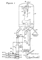
- a primary stream of regenertion (combustion) gas which may be air or another oxygen- containing gas, enters a line 7 and mixes with cokecontaminated catalyst entering via a conduit 8. These streams are shown as flowing together in a mixing conduit 11, although each stream could flow individually into the combustion zone 1.
- the resultant mixture of coke- contaminated catalyst and regeneration gas are distributed into the interior of combustion zone 1, at a lower locus thereof, via the conduit 11 and a distributor 13.
- Coke-contaminated catalyst commonly contains from about 0.1 to about 5 wt %. carbon, as coke. Coke is predominantly comprised of carbon, however, it can contain from about 5 to about 15 wt. % hydrogen, as well as sulfur and other materials.
- the regeneration gas and entrained catalyst flows upward from the lower part of combustion zone 1 to the upper part thereof in dilute phase.
- dilute phase means a catalyst/gas mixture of less and 480 kg/m 3 (30 Ibs/ft 3 ), and "dense phase” means such a mixture equal to or more than 480 kg/m 3 (30 Ibs/ft 3 ).
- Dilute phase conditions often consist of a catalyst/gas mixture of about 32 to 160 kg/m 3 (2 - 10 Ibs/ft 3 ) As the catalyst/gas mixture ascends within combustion zone 1, the heat of combustion of coke is liberated and absorbed by the now relatively carbon- free catalyst, in other words, by the regenerated catalyst.
- the rising catalyst/gas stream flows through a passage-way 10 and impinges upon a surface 12, which impingement changes the direction of flow of the stream. It is well known in the art that impingement of a fluidized particulate stream upon a surface, causing the stream to turn through some angle, can result in the separation from the stream of a portion of the solid material therein.
- the impingement of the catalyst/gas stream upon surface 12 causes almost all of the hot regenerated catalyst flowing from the combustion zone to disengage from the flue gas and fall to the bottom portion of the disengagement zone 2 which comprises a hot particle-collection chamber or fluid particle-collection section.
- the catalyst collection area of the disengagement zone may be a frusto-conical annular receptacle, as shown, or any other shape appropriate for collecting catalyst particles
- the gaseous products of coke oxidation and excess regeneration gas, or flue gas, and the very small uncollected portion of hot regenerated catalyst flow up through disengagement zone 2 and enter a separation means 15 through an inlet 14. Hot regenerated catalyst is returned to the FCC reactor via a conduit 33.
- the separation means 15 may be cyclone separators, as schematically shown in Figure 1, or any other effective means for the separation of catalyst from a gas stream.
- Catalyst separated from the flue gas falls to the bottom of disengagement zone 2 through conduits 16 and 17.
- the flue gas leaves the disengagement zone 2 via a conduit 18, through which it may proceed to an associated energy recovery system (not shown).
- Having the disengagement zone in upward communication with the combustion zone is advantageous, in comparison to schemes in which the gas/catalyst mixture flows upward into a relatively dense phase heat removal zone, in that with the former, there is a substantial reduction in the loading of the regenerator cyclones which virtually eliminates large losses of catalyst from FCC units during operational upsets.
- a portion of the catalyst collected in the disengaging zone as a first dense phase fluidized bed is passed in its dense phase, via a hot catalyst recycle conduit 4, downwardly into the cooling zone 3 which encloses vertical heat exchanger tubes 42.
- the cooling zone 3 is a chamber of vertical orientation with the catalyst flowing into the lower portion of the chamber and the heat exchange medium passing through the heat exchanger tubes via lines 9 and 29.
- the preferred heat exchange medium would be water, which would change at least partially from liquid to gas phase when passing through the tubes.
- the tube bundle in the heat exchanger will preferably be of the "bayonet" type wherein one end of the bundle is unattached, thereby minimizing problems due to the expansion and contraction of the heat exchanger components when exposed to and cooled from the very high regenerated catalyst temperatures.
- the heat transfer that occurs is, from the catalyst, through the tube walls and into the heat transfer medium.
- a second smaller stream of fluidizing combustion gas preferably air
- a control valve 20 is placed in the line 27.
- a control valve 24 in the conduit 4 regulates downward catalyst flow through the conduit 4 into the cooling zone 3.
- An associated control system will comprise some means 21 to sense the temperature in a portion of the combustion zone 1, such as the upper portion as shown, a temperature control means 22 having an adjustable set point being connected to the sensing means 21 and developing output signals, and means 23 and 23' for transmitting the output signals to the control valve 20 and the control valve 24, respectively, whereby the valves may be adjusted in response to the temperature at the upper portion of combustion zone 1.
- the temperature control means 22 which may incorporate an analogue or digital computer, will have the capability of selecting the optimum combination of fluidizing gas and catalyst flow rates. Such capability may be programmed into the control means 22 for a given system by one skilled in the art and will probably be based on empirical relationships derived from the observed operation of the system.
- the flow of fluidizing gas to the cooling zone 3 and the flow of catalyst through conduit 4 and cooling zone 3 will thereby be regulated. This regulates the mass velocity of the fluidized bed over the outside surfaces of the tubes by affecting the extent of turbulence and mass flow of the bed. This in turn regulates the heat transfer coefficient across such surfaces, and thus the quantity of heat transfer.
- the high degree of turbulence and backmixing that will occur in the fluidized bed of cooling zone 3 will ensure that the hot catalyst from conduit 4 will not "short circuit" through the uppermost portion of the cooling chamber 3 and pass into combustion chamber 1 without being cooled.
- Baffles can be employed within the cooling zone to ensure proper initial mixing.
- the cooled catalyst will flow horizontally from cooling zone 3 through heat exchange catalyst discharge conduit 5 into the lower portion of combustion chamber 1.
- the combustion gas used to fluidize the particles in the cooler will flow laterally into the combustion zone through the same conduit as the cooled catalyst.
- FIG. 1 Details are shown in Figure 1 of a preferred arrangement of heat exchanger in the cooling zone 3 and the manner of the interconnection of the cooling zone 3 with the disengagement zone 2 and the combustion zone 1.
- the heat exchanger 42 is embedded in a dense phase fluidized catalyst bed. Catalyst flows into the inlet of conduit 4 from the catalyst-collection section at the bottom of collection chamber 2 and flows through the conduit 4 into the cooling zone 3 via control valve 24. The catalyst and fluidizing gas mixture will leave the cooling zone 3 via conduit 5 since control valve 24 will effectively block egress of that mixture further up the conduit 4.
- An important feature of the present invention is that the fluidizing combustion gas that is used in the cooling zone 3 will leave the zone 3 via the conduit 5 and pass into the combustion zone 1 where it will serve as an additional source of combustion gas.
- This is in contra-distinction to previously discussed patents in which the cooling zone fluidizing gas is in a sense wasted because it is passed into the disengaging zone. The fluidizing gas is then unable to contribute to the regeneration of the catalyst in the combustion zone. Oxygen passed into the disengaging zone could support combustion within the disengaging zone. However, it is not normally desired to perform coke burnoff in the disengaging zone.
- the tube bundle 42 shown in the cooling zone 3 is of the bayonet type in which the tubes 42 are attached at the bottom or "head" of the heat exchanger, but not at any other location.
- a typical configuration of tubes in the bayonet type bundle would be 2.5 mm (one-inch) tubes each extending upward from inlet manifold 40 into the shell of the exchanger inside a 7.6 mm (three- inch) tube sealed at its top. Each smaller tube would empty into the larger tubes in which it is contained just below the sealed end of the larger tube.
- a liquid, such as water, would be passed into the smaller tubes, would empty into the larger tubes, would absorb heat from the hot catalyst through the wall of the larger tubes as it passed downward through the annular space in the larger tubes and would exit the heat exchanger, at least partially vaporized, from an outlet manifold 41.
- the vertical heat exchange tubes shown in Figure 1 can be replaced by tubes having various inclinations.
- the heat exchange tubes can be horizontal, as shown in Figure 2, or inclined at a 45° angle from the horizontal.
- the cooling coils of the present invention are entirely located within a lower portion of the cooling zone well below the point at which the conduit which removes cooled particles is attached to the cooling zone. This point divides the cooling zone into the upper and lower portions. Solely as an example, the upper end of the heat exchange tubes of the embodiment of Figure 1 should terminate at least about 6 to 9 m (2 to 3 feet) below the draw off conduit to the combustion zone. This is an important feature of the invention as it allows the heat exchange tubes to be totally covered with a dense settled blanket of catalyst particles. That is, by terminating or greatly reducing the flow of the fluidizing gas into the bottom of the chamber of the cooling zone, particles can be allowed to settle into the bottom portion of the chamber.
- the cooling coils are thereby insulated from hot catalyst particles entering the upper portion of the cooling zone.
- the heat exchanger tubes are thereby kept sufficiently cool to prevent them from being damaged by overheating when no coolant is flowing through the tubes. The heat exchanger may therefore be removed from service without exposing the tubes to severe damage. This is very useful when the tubes are not required (e. g. during startup procedures or during the processing of low coke- producing charge stocks).
- the heat exchanger tubes are also protected from erosion by the circulating particles when covered by the stagnant particles.
- the use of the invention does not foreclose the use of additional heat exchange coils at other points within the overall apparatus. For instance, other prior art type cooling coils may be located within the hot catalyst recycle conduit, the combustion chamber or at higher elevations within the cooling zone.
- Figure 2 illustrates the use of the invention using apparatus having a modified structure.
- the elements employed in Figure 2 are the same as those in Figure 1 except that the heat exchange bundle is directed horizontally rather than vertically as in Figure 1.
- the same numerals are employed in Figure 2 as in Figure 1.
- the numerals in Figure 2 will have a prime added to them to distinguish from the numerals of Figure 1 which identify the same equipment in a different orientation.
- Figure 2 also differs from Figure 1 in that an optional dipleg 45 shown in Figure 1 is not present in the apparatus of Figure 2. Therefore, in the apparatus of Figure 2 all the catalyst flowing from the upper disengaging zone to the lower combustion zone must pass through the hot catalyst recycle conduit 4.
- the steam is then collected in a manifold 41' and is removed from the process through a line 29'.
- the generation of steam within the heat exchange tubes removes heat from the hot catalyst passing through the cooling zone.
- the catalyst which spills over a vertical baffle 31 into the combustion zone from the cooling chamber 30 has therefore been cooled and will have a lower temperature relative to the hot catalyst descending through the conduit 4.
- the rate of heat removal in the cooling zone is controlled by the rate of flow of the fluidizing gas supplied to the cooling zone. This is in addition to the control which is providable by regulating the rate of flow of hot catalyst through the recycle conduit 4.
- the air which is the preferred fluidizing gas, enters through a line 27' at a rate controlled by a valve 20'. The air is then distributed at a plurality of points underneath the horizontal heat exchange tubes 42' through three conduits 25, 26 and 27'.
- the fluidizing gas can be distributed to a plurality of points underneath the heat exchange tubes a number of different ways. For instance, a fluidizing gas may be passed into the cooling zone through more than three separate conduits with four or more conduits being provided for this purpose.
- the fluidizing gas may pass into the cooling zone via a single conduit which is attached to a gas distribution means located underneath the heat exchange tubes.
- the gas would then flow into a single gas distribution grid or complex of pipes located within the cooling zone and exit from a multiplicity of openings provided within this grid.
- individual flow control devices could be provided on different fluidizing gas inlet conduits to further optimize the flow of the fluidizing gas through the dense phase catalyst bed retained within the cooling chamber and the catalyst mixing caused by the fluidization.
- the fluidization of the catalyst ci rculates it across the heat exchange coils.
- the fluidization also admixes cooled catalyst with hot catalyst descending through the recycle conduit. The discharge of the descending catalyst stream will also admix the catalyst.
- the bottom portion of the hot catalyst recycle conduit 4 is slanted toward the combustion zone. This is to direct the descending catalyst towards the overflow space or passage- way located above the baffle 31 such that the catalyst does not clog the flow path for catalyst between the conduit 4 and the combustion zone. Careful attention must be provided that the distance between the entrance point of the catalyst into the cooling zone and the point at which it enters the combustion chamber does not exceed that distance dictated by reference to the angle of repose of the catalyst within the cooling zone in an unfluidized state.
- the particle cooling zone (chamber) of the present invention is referred to herein as a "backmixed" cooler. This is in comparison to a "flow through” particle cooler.
- the term backmixed cooler is intended to refer to an indirect heat exchanger in which particles being cooled are churned or mixed in both vertical directions through the use of a fluidizing gas which is passed into a lower point in the cooler at least below the majority of the cooling coils. All conduits for particle flow are located in the upper portion of the cooling chamber. Heat is transported downward by the moving catalyst in the fluidized dense particle bed within the cooling chamber.
- the catalyst cooler shown in previously cited US-A-4 364 849 is a backmixed cooler.
- the catalyst flows through the heat exchange volume in single direction, usually downward.
- the cooler of US-A-4 425 301 is a flow- through cooler ( Figure 2 shows an upf low cooler).
- Fluidizing gas can be used as shown in this reference to regulate heat transfer in a flow- through cooler. It is essential that the quantity of particles or catalyst retained in cooling zone 3 is sufficient to maintain a depth of dense phase fluid catalyst bed which substantially submerges the tubes in a dense phase bed.
- baffle 31 shown in Figure 2 There are a number of ways of accomplishing this objective, one of which is to use the baffle 31 shown in Figure 2.
- the dipleg (or standpipe) 45 in Figure 1 is shown with a bottom flapper valve 46 and an upper collection pot 44.
- the upper edge of the collection pot serves as a weir which restrains catalyst flow into the dipleg. Catalyst which does not flow through the cooling zone 3 and conduit 33 will overflow the weir and fill the dipleg 45.
- catalyst will empty from the dipleg into the combustion chamber 1.
- the flapper valve and/or head of catalyst in the dipleg also serve to prevent undesired reversal of flow up the dipleg.
- the dense phase bed level and thus the catalyst head available to the cooling zone 3 will therefore be held at the level of the top of the collection pot 44.
- the above scheme provides the ability to remove heat from the FCC regenerator as required to maintain a maximum combustion zone temperature and at the same time maintains an acceptable degree of stable steady state operation conducive to the controllability and efficiency of the regenerator, all while enjoying flexibility and ease of operation of an external catalyst cooler or heat exchanger.
- the invention eliminates any requirement to operate cooling coils during start-up or during normal operation when it is not required.
- the invention also provides the efficiency of catalyst flue gas separation achieved by a disengagement zone which is unencumbered by a dense catalyst phase and heat removing paraphernalia. Furthermore, such scheme achieves the heretofore unrealized advantage of the subsequent use of fluidizing gas for combustion.
- This embodiment of the invention shown in Figure 1 may be characterized as an apparatus for the combustion of a combustible material present on fluidized solid particles
- apparatus comprises a vertically oriented combustion chamber; a second processing chamber located superadjacent to said combustion chamber and in communication therewith, and means to fluidize and transfer particles upward from the combustion chamber to the second processing chamber; a vertically oriented cooling chamber surrounding at least one heat exchanger of vertical orientation, the cooling chamber having a particle transfer opening with the entire heat exchanger being located below said particle transfer opening; a horizontal open passageway connecting said particle transfer opening of said cooling chamber with said combustion chamber and providing means for the flow of particles between said heat exchanger and said combustion chamber and for the flow of fluidizing combustion gas from the cooling chamber to the combustion chamber, a fluidizing combustion gas inlet conduit connected to a bottom portion of the cooling chamber providing means for the passage of a fluidizing gas onto the shell side of said heat exchanger and maintaining a fluidized catalyst bed within the cooling chamber, and means to control the flow of said fluidizing gas through said inlet conduit.
- the upper processing chamber may be a particle disengagement chamber such as shown in Figure 1.
- the upper processing chamber may be a second combustion chamber or stage. If the upper zone is also employed for combustion, a means to supply oxygen-containing combustion and fluidizing gas to the upper chamber is preferably also provided.
- the apparatus of Figure 1 may be imagined to have a second cooling zone, like cooling zone 3, along with all associated conduits, lines and valves.
- the particle flow rate through the additional cooler be fixed such that the particle flow rate and the quantity of the stream of fluidizing gas through the additional zone will result in the additional zone accounting for about 50 % of the total heat to be withdrawn from the combustion zone by the cooling zones.
- a restriction orifice of fixed dimensions placed in the conduit to the additional cooling zone in lieu of a control valve may effect the desired constant flow rate off particles therethrough for a specific pressure drop across the orifice.
- the pressure drop across the orifice may be largely fixed by fixing a constant depth of dense fluidized bed above the orifice by means such as the overflow weir of the collection pot 44.
Landscapes
- Chemical & Material Sciences (AREA)
- Oil, Petroleum & Natural Gas (AREA)
- Engineering & Computer Science (AREA)
- Organic Chemistry (AREA)
- Chemical Kinetics & Catalysis (AREA)
- General Chemical & Material Sciences (AREA)
- Combustion & Propulsion (AREA)
- Devices And Processes Conducted In The Presence Of Fluids And Solid Particles (AREA)
- Production Of Liquid Hydrocarbon Mixture For Refining Petroleum (AREA)
- Heat-Exchange Devices With Radiators And Conduit Assemblies (AREA)
Claims (9)
dadurch gekennzeichnet, daß der gesamte Wärmeaustauscher unter dem Teilchenauslaß (5) liegt und daß ein offener Durchgang den Teilchenauslaß der Kühlkammer (3) mit der Verbrennungskammer (1) verbindet und eine Einrichtung für den Fluß von gekühlten Teilchen und fluidisierendem Gas aus der Nachbarschaft des Wärmeaustauschers (42) zu der Verbrennungskammer (1) liefert.
Priority Applications (9)
| Application Number | Priority Date | Filing Date | Title |
|---|---|---|---|
| US06/687,352 US4578366A (en) | 1984-12-28 | 1984-12-28 | FCC combustion zone catalyst cooling process |
| AU54293/86A AU581296B2 (en) | 1984-12-28 | 1986-03-05 | Process and apparatus for simultaneously regenerating and cooling fluidized particles |
| ZA861797A ZA861797B (en) | 1984-12-28 | 1986-03-11 | Process and apparatus for simultaneously regenerating and cooling fluidized particles |
| AT86301760T ATE38393T1 (de) | 1984-12-28 | 1986-03-12 | Verfahren und vorrichtung fuer das gleichzeitige regenerieren und kuehlen von fluidizierten teilchen. |
| EP86301760A EP0236609B1 (de) | 1984-12-28 | 1986-03-12 | Verfahren und Vorrichtung für das gleichzeitige Regenerieren und Kühlen von fluidizierten Teilchen |
| DE8686301760T DE3661077D1 (en) | 1984-12-28 | 1986-03-12 | Process and apparatus for simultaneously regenerating and cooling fluidized particles |
| DD86288110A DD246484A5 (de) | 1984-12-28 | 1986-03-20 | Verfahren und vorrichtung fuer die gleichzeitige regenierung und kuehlung von wirbelschichtteilchen |
| HU861198A HU203687B (en) | 1984-12-28 | 1986-03-21 | Method and apparatus for simultaneous cooling and regenerating fluidized particles |
| CN 86101915 CN1007784B (zh) | 1986-03-12 | 1986-03-25 | 流化颗粒再生和冷却同时进行的方法和装置 |
Applications Claiming Priority (4)
| Application Number | Priority Date | Filing Date | Title |
|---|---|---|---|
| US06/687,352 US4578366A (en) | 1984-12-28 | 1984-12-28 | FCC combustion zone catalyst cooling process |
| ZA861797A ZA861797B (en) | 1984-12-28 | 1986-03-11 | Process and apparatus for simultaneously regenerating and cooling fluidized particles |
| EP86301760A EP0236609B1 (de) | 1984-12-28 | 1986-03-12 | Verfahren und Vorrichtung für das gleichzeitige Regenerieren und Kühlen von fluidizierten Teilchen |
| HU861198A HU203687B (en) | 1984-12-28 | 1986-03-21 | Method and apparatus for simultaneous cooling and regenerating fluidized particles |
Publications (2)
| Publication Number | Publication Date |
|---|---|
| EP0236609A1 EP0236609A1 (de) | 1987-09-16 |
| EP0236609B1 true EP0236609B1 (de) | 1988-11-02 |
Family
ID=36889183
Family Applications (1)
| Application Number | Title | Priority Date | Filing Date |
|---|---|---|---|
| EP86301760A Expired EP0236609B1 (de) | 1984-12-28 | 1986-03-12 | Verfahren und Vorrichtung für das gleichzeitige Regenerieren und Kühlen von fluidizierten Teilchen |
Country Status (8)
| Country | Link |
|---|---|
| US (1) | US4578366A (de) |
| EP (1) | EP0236609B1 (de) |
| AT (1) | ATE38393T1 (de) |
| AU (1) | AU581296B2 (de) |
| DD (1) | DD246484A5 (de) |
| DE (1) | DE3661077D1 (de) |
| HU (1) | HU203687B (de) |
| ZA (1) | ZA861797B (de) |
Families Citing this family (22)
| Publication number | Priority date | Publication date | Assignee | Title |
|---|---|---|---|---|
| EP0304523B1 (de) * | 1987-08-28 | 1992-07-08 | Exxon Research And Engineering Company | Apparat und Verfahren zur Temperaturkontrolle bei der Katalysatorregeneration |
| US4822761A (en) * | 1986-05-13 | 1989-04-18 | Ashland Oil, Inc. | Method and apparatus for cooling fluid solid particles used in a regeneration system |
| US4859424A (en) * | 1987-11-02 | 1989-08-22 | Uop | Conversion of stacked FCC unit |
| US4859308A (en) * | 1988-01-19 | 1989-08-22 | Mobil Oil Corporation | Two-stage process for conversion of alkanes to gasoline |
| US4840928A (en) * | 1988-01-19 | 1989-06-20 | Mobil Oil Corporation | Conversion of alkanes to alkylenes in an external catalyst cooler for the regenerator of a FCC unit |
| EP0332536B1 (de) * | 1988-03-09 | 1992-07-29 | Total Raffinage Distribution S.A. | Verfahren und Vorrichtung zum Regenerieren eines Katalysators in einem Fliessbett |
| FR2628342A1 (fr) * | 1988-03-09 | 1989-09-15 | Total France | Procede et dispositif de regeneration en lit fluidise d'un catalyseur |
| FR2633848B1 (fr) * | 1988-07-08 | 1991-05-31 | Inst Francais Du Petrole | Procede et dispositif de regeneration d'un catalyseur use avec echange thermique en lit fluidise |
| US4917790A (en) * | 1989-04-10 | 1990-04-17 | Mobil Oil Corporation | Heavy oil catalytic cracking process and apparatus |
| US5000841A (en) * | 1989-04-10 | 1991-03-19 | Mobil Oil Corporation | Heavy oil catalytic cracking process and apparatus |
| FR2648550B1 (fr) * | 1989-06-16 | 1995-01-27 | Inst Francais Du Petrole | Procede et dispositif de regulation ou controle du niveau thermique d'un solide pulverulent comportant un echangeur de chaleur a compartiments en lit fluidise ou mobile |
| CN1016271B (zh) * | 1990-03-07 | 1992-04-15 | 中国石油化工总公司北京设计院 | 外取热器 |
| US5198194A (en) * | 1990-06-08 | 1993-03-30 | Mobil Oil Corporation | Apparatus for simultaneous heating and cooling a fast fluidized bed catalyst regenerator |
| US5130012A (en) * | 1991-01-24 | 1992-07-14 | Mobil Oil Corporation | Process and apparatus for reducing NOx emissions from high-efficiency FFC regenerators |
| FI962653A7 (fi) | 1996-06-27 | 1997-12-28 | Foster Wheeler Energia Oy | Menetelmä ja laite kiinteistä hiukkasista tapahtuvan lämmön siirtymisen valvomiseksi leijupetireaktorissa |
| BR9703632A (pt) * | 1997-07-17 | 1999-02-23 | Petroleo Brasileiro Sa | Processo para craqueamento catalítico fluido de cargas pesadas |
| CA2731074C (en) * | 2008-07-17 | 2017-01-03 | Intercat Equipment, Inc. | Material delivery system to one or more units and methods of such delivery |
| MX2011002502A (es) | 2008-09-05 | 2011-05-27 | Intercat Equipment Inc | Aparato y metodos para el retiro de material para la regulacion de inventario de material en una o mas unidades. |
| CN102264870B (zh) * | 2008-12-23 | 2014-01-08 | 英特卡设备有限公司 | 调节一个或多个单元中物质存量的物质回收装置和方法 |
| US9309469B2 (en) * | 2009-09-30 | 2016-04-12 | Johnson Matthey Process Technologies, Inc. | Apparatus and method for controlling or adding material to one or more units |
| DE102011054718B4 (de) * | 2011-10-21 | 2014-02-13 | Hitachi Power Europe Gmbh | Verfahren zur Erzeugung einer Spannungsverminderung in errichteten Rohrwänden eines Dampferzeugers |
| JP2018535092A (ja) * | 2015-11-24 | 2018-11-29 | シエル・インターナシヨネイル・リサーチ・マーチヤツピイ・ベー・ウイShell Internationale Research Maatschappij Besloten Vennootshap | 粒子離脱デバイス |
Family Cites Families (19)
| Publication number | Priority date | Publication date | Assignee | Title |
|---|---|---|---|---|
| US2515156A (en) * | 1941-07-24 | 1950-07-11 | Standard Oil Dev Co | Fluidized catalyst apparatus |
| US2377657A (en) * | 1941-08-30 | 1945-06-05 | Standard Oil Co | Catalytic hydrocarbon conversion system |
| US2492948A (en) * | 1945-10-05 | 1950-01-03 | Universal Oil Prod Co | Controlling catalyst regeneration temperature |
| US2506123A (en) * | 1947-06-27 | 1950-05-02 | Sinclair Refining Co | Apparatus for pyrolytic conversion of hydrocarbons |
| US2596748A (en) * | 1948-07-10 | 1952-05-13 | Sinclair Refining Co | Catalyst regeneration system |
| US2873175A (en) * | 1952-09-10 | 1959-02-10 | Kellogg M W Co | Apparatus for catalytic conversion of hydrocarbon fluids |
| US2862798A (en) * | 1954-06-11 | 1958-12-02 | Standard Oil Co | Fluidized catalyst regeneration system |
| US2819951A (en) * | 1955-02-23 | 1958-01-14 | Shell Dev | Apparatus for the regeneration of catalyst |
| US2970117A (en) * | 1957-05-10 | 1961-01-31 | Phillips Petroleum Co | Catalyst regeneration and apparatus therefor |
| US3990992A (en) * | 1974-04-12 | 1976-11-09 | Standard Oil Company | Regeneration of cracking catalyst in a vessel with a partition forming an upper and lower zone |
| US4219442A (en) * | 1978-12-14 | 1980-08-26 | Uop Inc. | Fluid coke contaminated catalyst regeneration process |
| US4434245A (en) * | 1981-06-15 | 1984-02-28 | Uop Inc. | Fluid particle cooling process and apparatus |
| US4353812A (en) * | 1981-06-15 | 1982-10-12 | Uop Inc. | Fluid catalyst regeneration process |
| US4425301A (en) * | 1981-08-03 | 1984-01-10 | Uop Inc. | Fluid catalyst regeneration apparatus |
| US4374750A (en) * | 1981-08-03 | 1983-02-22 | Uop Inc. | Fluid catalyst regeneration process and apparatus |
| US4396531A (en) * | 1981-08-13 | 1983-08-02 | Uop Inc. | Fluid catalyst regeneration process and apparatus |
| US4434044A (en) * | 1981-09-01 | 1984-02-28 | Ashland Oil, Inc. | Method for recovering sulfur oxides from CO-rich flue gas |
| US4364849A (en) * | 1981-09-14 | 1982-12-21 | Uop Inc. | Fluid catalyst regeneration process and apparatus |
| EP0105980B1 (de) * | 1982-10-06 | 1986-01-29 | Uop Inc. | Verfahren und Anlage zur Kühlung von Partikeln mit einem Fluidum unter Rückmischung der Partikel |
-
1984
- 1984-12-28 US US06/687,352 patent/US4578366A/en not_active Expired - Lifetime
-
1986
- 1986-03-05 AU AU54293/86A patent/AU581296B2/en not_active Ceased
- 1986-03-11 ZA ZA861797A patent/ZA861797B/xx unknown
- 1986-03-12 DE DE8686301760T patent/DE3661077D1/de not_active Expired
- 1986-03-12 AT AT86301760T patent/ATE38393T1/de not_active IP Right Cessation
- 1986-03-12 EP EP86301760A patent/EP0236609B1/de not_active Expired
- 1986-03-20 DD DD86288110A patent/DD246484A5/de not_active IP Right Cessation
- 1986-03-21 HU HU861198A patent/HU203687B/hu not_active IP Right Cessation
Also Published As
| Publication number | Publication date |
|---|---|
| HUT43273A (en) | 1987-10-28 |
| AU5429386A (en) | 1987-09-10 |
| ZA861797B (en) | 1986-11-26 |
| ATE38393T1 (de) | 1988-11-15 |
| AU581296B2 (en) | 1989-02-16 |
| US4578366A (en) | 1986-03-25 |
| DD246484A5 (de) | 1987-06-10 |
| DE3661077D1 (en) | 1988-12-08 |
| EP0236609A1 (de) | 1987-09-16 |
| HU203687B (en) | 1991-09-30 |
Similar Documents
| Publication | Publication Date | Title |
|---|---|---|
| EP0236609B1 (de) | Verfahren und Vorrichtung für das gleichzeitige Regenerieren und Kühlen von fluidizierten Teilchen | |
| US4710357A (en) | FCC combustion zone catalyst cooling apparatus | |
| US4439533A (en) | Fluid particle backmixed cooling process | |
| US4353812A (en) | Fluid catalyst regeneration process | |
| US5212129A (en) | Inverted backmix coolers for FCC units | |
| US4434245A (en) | Fluid particle cooling process and apparatus | |
| US4923834A (en) | Side mounted coolers with improved backmix cooling in FCC regeneration | |
| US5128292A (en) | Side mounted coolers with improved backmix cooling in FCC regeneration | |
| EP0105980B1 (de) | Verfahren und Anlage zur Kühlung von Partikeln mit einem Fluidum unter Rückmischung der Partikel | |
| US4374750A (en) | Fluid catalyst regeneration process and apparatus | |
| US4396531A (en) | Fluid catalyst regeneration process and apparatus | |
| AU618841B2 (en) | Heat exchanger for cooling fluidized particles with backmix and flow through modes of operation | |
| US4424192A (en) | Fluid catalyst regeneration apparatus | |
| US4309308A (en) | Fluid catalyst regeneration process and apparatus | |
| US4364849A (en) | Fluid catalyst regeneration process and apparatus | |
| US4425301A (en) | Fluid catalyst regeneration apparatus | |
| US4387043A (en) | Fluid catalyst regeneration process and apparatus | |
| US4757039A (en) | Dual function heat withdrawal in a fluidized catalytic cracking-regeneration process | |
| US5409872A (en) | FCC process and apparatus for cooling FCC catalyst during regeneration | |
| US4483276A (en) | Fluid particle backmixed cooling apparatus | |
| US4438071A (en) | Fluid catalyst regeneration apparatus | |
| US4243634A (en) | Fluid catalyst regeneration apparatus | |
| US4859424A (en) | Conversion of stacked FCC unit | |
| US4971767A (en) | Manway cooler--method and apparatus | |
| US4371453A (en) | Fluid catalyst regeneration process and apparatus |
Legal Events
| Date | Code | Title | Description |
|---|---|---|---|
| PUAI | Public reference made under article 153(3) epc to a published international application that has entered the european phase |
Free format text: ORIGINAL CODE: 0009012 |
|
| AK | Designated contracting states |
Kind code of ref document: A1 Designated state(s): AT BE DE FR GB IT NL SE |
|
| 17P | Request for examination filed |
Effective date: 19870908 |
|
| 17Q | First examination report despatched |
Effective date: 19880113 |
|
| GRAA | (expected) grant |
Free format text: ORIGINAL CODE: 0009210 |
|
| AK | Designated contracting states |
Kind code of ref document: B1 Designated state(s): AT BE DE FR GB IT NL SE |
|
| PG25 | Lapsed in a contracting state [announced via postgrant information from national office to epo] |
Ref country code: SE Effective date: 19881102 Ref country code: AT Effective date: 19881102 |
|
| REF | Corresponds to: |
Ref document number: 38393 Country of ref document: AT Date of ref document: 19881115 Kind code of ref document: T |
|
| REF | Corresponds to: |
Ref document number: 3661077 Country of ref document: DE Date of ref document: 19881208 |
|
| ET | Fr: translation filed | ||
| ITF | It: translation for a ep patent filed | ||
| PLBE | No opposition filed within time limit |
Free format text: ORIGINAL CODE: 0009261 |
|
| STAA | Information on the status of an ep patent application or granted ep patent |
Free format text: STATUS: NO OPPOSITION FILED WITHIN TIME LIMIT |
|
| 26N | No opposition filed | ||
| ITTA | It: last paid annual fee | ||
| PGFP | Annual fee paid to national office [announced via postgrant information from national office to epo] |
Ref country code: FR Payment date: 20000202 Year of fee payment: 15 |
|
| PGFP | Annual fee paid to national office [announced via postgrant information from national office to epo] |
Ref country code: GB Payment date: 20000222 Year of fee payment: 15 Ref country code: DE Payment date: 20000222 Year of fee payment: 15 |
|
| PGFP | Annual fee paid to national office [announced via postgrant information from national office to epo] |
Ref country code: NL Payment date: 20000223 Year of fee payment: 15 |
|
| PGFP | Annual fee paid to national office [announced via postgrant information from national office to epo] |
Ref country code: BE Payment date: 20000317 Year of fee payment: 15 |
|
| PG25 | Lapsed in a contracting state [announced via postgrant information from national office to epo] |
Ref country code: GB Free format text: LAPSE BECAUSE OF NON-PAYMENT OF DUE FEES Effective date: 20010312 |
|
| PG25 | Lapsed in a contracting state [announced via postgrant information from national office to epo] |
Ref country code: BE Free format text: LAPSE BECAUSE OF NON-PAYMENT OF DUE FEES Effective date: 20010331 |
|
| BERE | Be: lapsed |
Owner name: UOP INC. Effective date: 20010331 |
|
| PG25 | Lapsed in a contracting state [announced via postgrant information from national office to epo] |
Ref country code: NL Free format text: LAPSE BECAUSE OF NON-PAYMENT OF DUE FEES Effective date: 20011001 |
|
| GBPC | Gb: european patent ceased through non-payment of renewal fee |
Effective date: 20010312 |
|
| PG25 | Lapsed in a contracting state [announced via postgrant information from national office to epo] |
Ref country code: FR Free format text: LAPSE BECAUSE OF NON-PAYMENT OF DUE FEES Effective date: 20011130 |
|
| NLV4 | Nl: lapsed or anulled due to non-payment of the annual fee |
Effective date: 20011001 |
|
| REG | Reference to a national code |
Ref country code: FR Ref legal event code: ST |
|
| PG25 | Lapsed in a contracting state [announced via postgrant information from national office to epo] |
Ref country code: DE Free format text: LAPSE BECAUSE OF NON-PAYMENT OF DUE FEES Effective date: 20020101 |
|
| PG25 | Lapsed in a contracting state [announced via postgrant information from national office to epo] |
Ref country code: IT Free format text: LAPSE BECAUSE OF NON-PAYMENT OF DUE FEES;WARNING: LAPSES OF ITALIAN PATENTS WITH EFFECTIVE DATE BEFORE 2007 MAY HAVE OCCURRED AT ANY TIME BEFORE 2007. THE CORRECT EFFECTIVE DATE MAY BE DIFFERENT FROM THE ONE RECORDED. Effective date: 20050312 |