EP0236647A1 - Wirbelbettwärmeerzeuger mit Mitteln für Aschenbeseitigung und Wärmerückgewinnung - Google Patents
Wirbelbettwärmeerzeuger mit Mitteln für Aschenbeseitigung und Wärmerückgewinnung Download PDFInfo
- Publication number
- EP0236647A1 EP0236647A1 EP86402830A EP86402830A EP0236647A1 EP 0236647 A1 EP0236647 A1 EP 0236647A1 EP 86402830 A EP86402830 A EP 86402830A EP 86402830 A EP86402830 A EP 86402830A EP 0236647 A1 EP0236647 A1 EP 0236647A1
- Authority
- EP
- European Patent Office
- Prior art keywords
- hearth
- tubes
- generator according
- central
- volume
- Prior art date
- Legal status (The legal status is an assumption and is not a legal conclusion. Google has not performed a legal analysis and makes no representation as to the accuracy of the status listed.)
- Granted
Links
- 238000011084 recovery Methods 0.000 title 1
- 230000002093 peripheral effect Effects 0.000 claims abstract description 35
- XLYOFNOQVPJJNP-UHFFFAOYSA-N water Substances O XLYOFNOQVPJJNP-UHFFFAOYSA-N 0.000 claims abstract description 28
- 239000000779 smoke Substances 0.000 claims abstract description 25
- 238000005243 fluidization Methods 0.000 claims abstract description 10
- 238000004891 communication Methods 0.000 claims description 10
- 239000003517 fume Substances 0.000 claims description 9
- 239000012528 membrane Substances 0.000 claims description 5
- 239000002956 ash Substances 0.000 description 16
- 235000002918 Fraxinus excelsior Nutrition 0.000 description 9
- 238000010276 construction Methods 0.000 description 5
- 239000000463 material Substances 0.000 description 5
- 239000000446 fuel Substances 0.000 description 4
- 238000002485 combustion reaction Methods 0.000 description 3
- 239000000428 dust Substances 0.000 description 3
- 230000003628 erosive effect Effects 0.000 description 2
- 238000004519 manufacturing process Methods 0.000 description 2
- 235000011837 pasties Nutrition 0.000 description 2
- 238000009417 prefabrication Methods 0.000 description 2
- 238000006477 desulfuration reaction Methods 0.000 description 1
- 230000023556 desulfurization Effects 0.000 description 1
- 239000010791 domestic waste Substances 0.000 description 1
- 238000000605 extraction Methods 0.000 description 1
- 239000007789 gas Substances 0.000 description 1
- 239000008187 granular material Substances 0.000 description 1
- 238000011065 in-situ storage Methods 0.000 description 1
- 238000009776 industrial production Methods 0.000 description 1
- 238000009434 installation Methods 0.000 description 1
- 238000000034 method Methods 0.000 description 1
- 239000002245 particle Substances 0.000 description 1
- 238000005192 partition Methods 0.000 description 1
- 239000003208 petroleum Substances 0.000 description 1
- 230000002028 premature Effects 0.000 description 1
- 238000004064 recycling Methods 0.000 description 1
- 239000010802 sludge Substances 0.000 description 1
- 239000007787 solid Substances 0.000 description 1
- 239000004449 solid propellant Substances 0.000 description 1
- 238000011144 upstream manufacturing Methods 0.000 description 1
- 238000003466 welding Methods 0.000 description 1
Images

Classifications
-
- F—MECHANICAL ENGINEERING; LIGHTING; HEATING; WEAPONS; BLASTING
- F22—STEAM GENERATION
- F22B—METHODS OF STEAM GENERATION; STEAM BOILERS
- F22B31/00—Modifications of boiler construction, or of tube systems, dependent on installation of combustion apparatus; Arrangements or dispositions of combustion apparatus
- F22B31/0007—Modifications of boiler construction, or of tube systems, dependent on installation of combustion apparatus; Arrangements or dispositions of combustion apparatus with combustion in a fluidized bed
- F22B31/0046—Modifications of boiler construction, or of tube systems, dependent on installation of combustion apparatus; Arrangements or dispositions of combustion apparatus with combustion in a fluidized bed for boilers of the shell type, e.g. with furnace box
- F22B31/0053—Modifications of boiler construction, or of tube systems, dependent on installation of combustion apparatus; Arrangements or dispositions of combustion apparatus with combustion in a fluidized bed for boilers of the shell type, e.g. with furnace box with auxiliary water tubes
Definitions
- the subject of the invention is a moderate power thermal generator with a fluidized bed comprising improved means for evacuating the centers and recovering heat, usable in particular for solid fuels in particles (coals, granules of household waste, etc.). .) or pasty (heavy petroleum fractions, residual sludge, etc.).
- a generator of this type operating according to the fluidized bed combustion technique has the advantage of using a wide range of fuels.
- the production of such a generator poses construction and industrialization problems linked to the evacuation of the centers and the treatment of the fumes.
- the main object of the invention is to achieve a generator of the type indicated above with which the difficulties set out above are overcome substantially if not totally, in a simple and effective manner.
- this peripheral envelope limits with the central hearth at least one intermediate volume which is placed in communication with the central hearth in its upper part by openings for smoke and which is connected at its lower part to smoke tubes, by a first end thereof; these smoke tubes extend in the peripheral envelope over a substantial part of their length and are connected by their second end to the smoke outlet duct.
- the intermediate volume thus created is advantageously provided at its lower part with a collector for collecting and extracting the ash entrained by the fumes.
- the intermediate volume constitutes a primary dust collector which is integrated into the generator upstream of the smoke tubes and which protects these tubes against the risks of fouling and premature erosion.
- This arrangement avoids the use of a smoke box which is often produced by mechanical welding and which is attached using flanges on the heat generator.
- the compactness of the generator according to the invention is improved and the prefabrication is facilitated.
- the fluidized bed hearth has at least one side wall with water tubes surrounded by the peripheral envelope with a symmetrical arrangement which avoids the problems of differential expansion and resistance over time of the generator.
- the vertical wall is made up of water tubes joined in a sealed manner by membranes; this construction method facilitates industrial production of the generator and improves heat transfer.
- the fluidization grid is part of the filled enclosure of water which is placed in communication with the peripheral envelope.
- This design allows a lowering of the temperature of the grid, which allows its manufacture in economical material.
- all the walls delimiting the fluidized bed, including the grid itself, thus participate in the heat exchange. This makes it possible to reduce the exchange surfaces to be immersed in the bed; it follows that the tubes constituting these exchange surfaces can be arranged more freely, avoiding the areas where a strong erosion would occur.
- the fluidization grid used in the thermal generator according to the invention is in itself of a known type; this may in particular be a grid with openings flared upwards, such as those which are the subject of documents FR-A- Nos 2 171 945, 2 519 877, 85-08320, 85-15580.
- At least one of the walls of the hearth has one (or more sieuurss) opening (s) provided (s) with a selective closing means; this opening makes it possible to regulate the level of the fluidized bed.
- the ash collector contains a water circulation loop connected to the hollow peripheral envelope. This loop completes the thermal exhaustion of the ashes and further improves the efficiency of the unit.
- the generator has a device for re-injecting the ash collected by a final dust collector (for example a multi-cyclone) connected to the smoke circuit at the outlet of the boiler.
- a final dust collector for example a multi-cyclone
- This device thus makes it possible to improve the desulfurization in situ, to reduce unburnt residues and to limit the extraction points of the ashes.
- This device can be produced, for example, pneumatically, bypassing the arrival of fluidizing air or secondary air or mechanically by conveying using a conveyor screw.
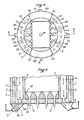
- a generator according to the invention comprises a hearth 1 with a fluidized bed, with side wall, of a type known per se and a peripheral casing 2 which envelops the hearth 1 by limiting with the side wall 3 of the latter an intermediate volume 4.
- the hearth 1 could be cylindrical as well as the peripheral envelope 2, so that the intermediate volume 4 would be an annular volume.
- openings 5 put it in communication with the intermediate volume 4.
- the hearth 1 has a generally rectangular configuration; the peripheral envelope 2 is cylindrical and it limits, with the hearth 1, two separate and opposite intermediate volumes 4A, 4B which are each located on a long side of the hearth 1.
- the two long sides 3A, 3B of the hearth 1 are formed by tubes of parallel, spaced 3C water, connected to each other in a sealed manner by 3D intermediate membranes, in a manner known per se.
- certain tubes, preferably one tube out of two, are offset towards the exterior of the hearth 1 and the 3D intermediate membranes are eliminated in the remote end portion of each tube 3C.
- the upper openings 5 are thus obtained through which the fumes from the hearth 1 can circulate.
- the hearth 1 is closed at its upper part, at a level higher than that of the openings 5, by an upper wall 1A which projects beyond the hearth 1 and which also closes the intermediate volumes 4A, 4B.
- the fumes can enter the latter only through the upper openings 5.
- the peripheral envelope 2 also covers the hearth 1 above this upper wall 1A. In this way, the peripheral envelope extends around the side wall and the upper wall of the hearth 1; it wraps the latter completely on all sides.
- the peripheral envelope 2 is closed by an upper wall 6.
- the latter supports a smoke outlet duct 7.
- the peripheral envelope 2 is divided by interior, radial partitions 6A, 6B, 6C, 6D forming four compartments opposite two by two.
- Two opposite compartments, of larger dimension in circumferential direction 8A and 8C contain vertical tubes 9, spaced apart, which extend between the lower wall 10 of the peripheral envelope 2 and its upper wall 6. These tubes 9 pass through this upper wall 6 and open into the smoke outlet duct 7.
- each tube 9 crosses the lower wall 10 and opens into an ash collector 11.
- An ash collector 11 is provided under each of the two compartments 8A, 8C of the peripheral envelope 2.
- Each collector 11 extends below the lower wall 10 and it communicates by a lower passage 11A with a corresponding intermediate volume 4A, 4B.
- the combustion fumes coming from the upper passages 5 descend into the intermediate volumes diaries 4A, 4B, use the collectors 11 and rise in the tubes 9 to reach the flue outlet duct 7.
- Each collector 11 has a depth sufficient for ashes to collect therein without the circulation of smoke being interrupted.
- each collector 11 is equipped at 12 with pneumatic means known per se, for extracting the ashes and for reintroducing these ashes inside the fluidized bed, to ensure their recycling.
- the two other opposite compartments 8B, 8D are provided, respectively, with a water inlet 13 and a water outlet 14.
- these two compartments are connected directly, through the hearth 1, by tubes of water 15 (visible only in FIG. 1) which are drowned during operation in the bed 16 of fluidized combustible material.
- tubes of water 15 visible only in FIG. 1
- a pipe 18 crosses from top to bottom the smoke outlet duct 7, the upper wall 6 of the peripheral envelope 2, the upper wall 1A of the hearth 1 to extend inside the latter and stop at the above the upper level of the fluidized bed 16.
- This pipe 18 serves to supply the hearth 1 with fuel. It will be noted that the invention is compatible with other modes of supplying the hearth 1 with fuel.
- the pipe 18 is cooled by a forced water circulation loop connected in bypass to the general supply input / output circuit.
- the grid 19 is represented as a hollow grid having an internal volume 19A into which the water tubes 3 open, by their lower end. These tubes 3 are therefore joined to the peripheral envelope 2 at the level of the grid 19.
- the fluidization grid 19 ⁇ is of conventional construction and it rests on a hollow enclosure 20 which supports it and whose internal volume is placed in communication with the internal volume of the peripheral envelope 2.
- this hollow enclosure 20 is traversed in a sealed manner by tubes 21 which supply fluidization gas to the usual orifices of the grid 19 gaz.
- the grid is of conventional construction; it is neither cooled nor supported by a cooled hollow enclosure.
- the ashes are collected without bulky material means and can then be disposed of easily, either to dispose of them definitively or to recycle them in the fluidized bed.
- the compartments 8B, 8D can also be eliminated; the peripheral envelope 2 then becomes a single envelope annularly surrounding the side wall of the hearth 1.
- the latter can be cylindrical and the intermediate volume 4 can also annularly surround the side wall of the hearth 1.
Landscapes
- Engineering & Computer Science (AREA)
- Chemical & Material Sciences (AREA)
- Combustion & Propulsion (AREA)
- Physics & Mathematics (AREA)
- Thermal Sciences (AREA)
- Mechanical Engineering (AREA)
- General Engineering & Computer Science (AREA)
- Fluidized-Bed Combustion And Resonant Combustion (AREA)
- Devices And Processes Conducted In The Presence Of Fluids And Solid Particles (AREA)
- Crucibles And Fluidized-Bed Furnaces (AREA)
- Processing Of Solid Wastes (AREA)
- Physical Or Chemical Processes And Apparatus (AREA)
- Solid-Fuel Combustion (AREA)
- Gasification And Melting Of Waste (AREA)
- Buildings Adapted To Withstand Abnormal External Influences (AREA)
- Adhesives Or Adhesive Processes (AREA)
- Cooling Or The Like Of Electrical Apparatus (AREA)
- Medicines Containing Antibodies Or Antigens For Use As Internal Diagnostic Agents (AREA)
- Thermotherapy And Cooling Therapy Devices (AREA)
Priority Applications (1)
| Application Number | Priority Date | Filing Date | Title |
|---|---|---|---|
| AT86402830T ATE45794T1 (de) | 1985-12-18 | 1986-12-16 | Wirbelbettwaermeerzeuger mit mitteln fuer aschenbeseitigung und waermerueckgewinnung. |
Applications Claiming Priority (2)
| Application Number | Priority Date | Filing Date | Title |
|---|---|---|---|
| FR8518764 | 1985-12-18 | ||
| FR8518764A FR2591722B1 (fr) | 1985-12-18 | 1985-12-18 | Generateur thermique a lit fluidise a moyens ameliores d'evacuation des cendres et de recuperation de chaleur |
Publications (2)
| Publication Number | Publication Date |
|---|---|
| EP0236647A1 true EP0236647A1 (de) | 1987-09-16 |
| EP0236647B1 EP0236647B1 (de) | 1989-08-23 |
Family
ID=9325923
Family Applications (1)
| Application Number | Title | Priority Date | Filing Date |
|---|---|---|---|
| EP86402830A Expired EP0236647B1 (de) | 1985-12-18 | 1986-12-16 | Wirbelbettwärmeerzeuger mit Mitteln für Aschenbeseitigung und Wärmerückgewinnung |
Country Status (18)
| Country | Link |
|---|---|
| US (1) | US4736711A (de) |
| EP (1) | EP0236647B1 (de) |
| JP (1) | JPS62175505A (de) |
| CN (1) | CN1008656B (de) |
| AT (1) | ATE45794T1 (de) |
| AU (1) | AU581160B2 (de) |
| CA (1) | CA1294499C (de) |
| DE (2) | DE236647T1 (de) |
| DK (1) | DK164715C (de) |
| ES (1) | ES2000154B3 (de) |
| FI (1) | FI865169A7 (de) |
| FR (1) | FR2591722B1 (de) |
| GR (2) | GR880300086T1 (de) |
| IN (1) | IN169114B (de) |
| NO (1) | NO162485C (de) |
| PT (1) | PT83940B (de) |
| YU (1) | YU46036B (de) |
| ZA (1) | ZA869456B (de) |
Cited By (1)
| Publication number | Priority date | Publication date | Assignee | Title |
|---|---|---|---|---|
| EP0398814A1 (de) * | 1989-05-19 | 1990-11-22 | CHARBONNAGES DE FRANCE, Etablissement public dit: | Vorrichtung zum Extrahieren von Materialteilchen aus einem Wirbelbett aus einem Wirbelbettgefäss |
Families Citing this family (10)
| Publication number | Priority date | Publication date | Assignee | Title |
|---|---|---|---|---|
| SE459987B (sv) * | 1987-12-23 | 1989-08-28 | Abb Stal Ab | Saett att kyla aska och kraftanlaeggning med en anordning foer askkylning |
| DE4005305A1 (de) * | 1990-02-20 | 1991-08-22 | Metallgesellschaft Ag | Wirbelschichtreaktor |
| US5484476A (en) * | 1994-01-11 | 1996-01-16 | Electric Power Research Institute, Inc. | Method for preheating fly ash |
| US7540384B2 (en) * | 2004-10-12 | 2009-06-02 | Great River Energy | Apparatus and method of separating and concentrating organic and/or non-organic material |
| US8062410B2 (en) | 2004-10-12 | 2011-11-22 | Great River Energy | Apparatus and method of enhancing the quality of high-moisture materials and separating and concentrating organic and/or non-organic material contained therein |
| US7987613B2 (en) * | 2004-10-12 | 2011-08-02 | Great River Energy | Control system for particulate material drying apparatus and process |
| US7275644B2 (en) * | 2004-10-12 | 2007-10-02 | Great River Energy | Apparatus and method of separating and concentrating organic and/or non-organic material |
| US8579999B2 (en) * | 2004-10-12 | 2013-11-12 | Great River Energy | Method of enhancing the quality of high-moisture materials using system heat sources |
| US8523963B2 (en) * | 2004-10-12 | 2013-09-03 | Great River Energy | Apparatus for heat treatment of particulate materials |
| CN110864280B (zh) * | 2018-08-28 | 2021-05-04 | 国家能源投资集团有限责任公司 | 燃烧含碳固体燃料的反应器和装置以及含碳固体燃料的燃烧方法 |
Citations (6)
| Publication number | Priority date | Publication date | Assignee | Title |
|---|---|---|---|---|
| DE2029155A1 (de) * | 1969-06-12 | 1970-12-23 | ||
| EP0016607A1 (de) * | 1979-03-14 | 1980-10-01 | The British Petroleum Company p.l.c. | Fliessbett-Verbrennungsvorrichtung |
| EP0028458A2 (de) * | 1979-10-03 | 1981-05-13 | Sandfire (Proprietary) Limited | Dampferzeuger mit Wirbelschicht-Brennkammer |
| GB2077616A (en) * | 1980-06-10 | 1981-12-23 | Parkinson Cowan Appliances Ltd | Fluidised bed boiler |
| GB2109096A (en) * | 1981-07-24 | 1983-05-25 | Duncomb Wallace Walker | Locomotive boiler fired by fluidised bed combustion |
| EP0005964B1 (de) * | 1978-05-31 | 1984-03-07 | Deborah Fluidised Combustion Limited | Kessel und Verbrennungsvorrichtung hierfür |
Family Cites Families (12)
| Publication number | Priority date | Publication date | Assignee | Title |
|---|---|---|---|---|
| US1684201A (en) * | 1927-02-26 | 1928-09-11 | Pollock James | Boiler for utilizing fine coal |
| US2832320A (en) * | 1953-12-14 | 1958-04-29 | Thome Robert | Gas-fired boiler, more particularly for central heating plants |
| BE795348A (fr) * | 1972-02-16 | 1973-05-29 | Charbonnages De France | Dispositif d'alimentation en gaz d'un reacteur de traitement par fluidisation |
| GB1513795A (en) * | 1976-04-14 | 1978-06-07 | Coal Ind | Boilers |
| GB1604999A (en) * | 1978-05-31 | 1981-12-16 | Deborah Fluidised Combustion | Boilers |
| GB2073910A (en) * | 1980-04-11 | 1981-10-21 | World Energy Resources Consult | Controls for fluidised bed burners |
| NZ197338A (en) * | 1980-06-10 | 1985-03-20 | Thorn Emi Energy Dev | Fluidised bed boiler |
| US4349969A (en) * | 1981-09-11 | 1982-09-21 | Foster Wheeler Energy Corporation | Fluidized bed reactor utilizing zonal fluidization and anti-mounding pipes |
| FR2519877B1 (fr) * | 1982-01-20 | 1986-10-31 | Charbonnages De France | Grille de fluidisation ainsi que foyer de combustion a grille inferieure de soufflage d'air et procede de traitement de matiere particulaire dans une chambre de fluidisation et/ou d'entrainement |
| FR2556075B1 (fr) * | 1983-12-02 | 1988-08-19 | Charbonnages De France | Foyer de combustion pour chaudiere a lit fluidise |
| US4565184A (en) * | 1984-05-17 | 1986-01-21 | Collins Bruce H | Combustible particulate fuel heater |
| FR2582540B1 (fr) * | 1985-06-03 | 1992-05-22 | Charbonnages De France | Dispositif de controle de l'alimentation en gaz de fluidisation des ouvertures de soufflage d'une grille de fluidisation et grille munie de ce dispositif |
-
1985
- 1985-12-18 FR FR8518764A patent/FR2591722B1/fr not_active Expired
-
1986
- 1986-12-10 US US06/940,079 patent/US4736711A/en not_active Expired - Fee Related
- 1986-12-16 EP EP86402830A patent/EP0236647B1/de not_active Expired
- 1986-12-16 IN IN978/MAS/86A patent/IN169114B/en unknown
- 1986-12-16 DE DE198686402830T patent/DE236647T1/de active Pending
- 1986-12-16 DE DE8686402830T patent/DE3665214D1/de not_active Expired
- 1986-12-16 PT PT83940A patent/PT83940B/pt not_active IP Right Cessation
- 1986-12-16 AT AT86402830T patent/ATE45794T1/de active
- 1986-12-16 ES ES86402830T patent/ES2000154B3/es not_active Expired
- 1986-12-17 FI FI865169A patent/FI865169A7/fi not_active Application Discontinuation
- 1986-12-17 NO NO865108A patent/NO162485C/no unknown
- 1986-12-17 CN CN86108550A patent/CN1008656B/zh not_active Expired
- 1986-12-17 YU YU216386A patent/YU46036B/sh unknown
- 1986-12-17 DK DK608486A patent/DK164715C/da not_active IP Right Cessation
- 1986-12-17 CA CA000525603A patent/CA1294499C/fr not_active Expired - Lifetime
- 1986-12-17 ZA ZA869456A patent/ZA869456B/xx unknown
- 1986-12-18 AU AU66791/86A patent/AU581160B2/en not_active Ceased
- 1986-12-18 JP JP61300185A patent/JPS62175505A/ja active Pending
-
1988
- 1988-12-16 GR GR88300086T patent/GR880300086T1/el unknown
-
1989
- 1989-08-24 GR GR89400116T patent/GR3000135T3/el unknown
Patent Citations (6)
| Publication number | Priority date | Publication date | Assignee | Title |
|---|---|---|---|---|
| DE2029155A1 (de) * | 1969-06-12 | 1970-12-23 | ||
| EP0005964B1 (de) * | 1978-05-31 | 1984-03-07 | Deborah Fluidised Combustion Limited | Kessel und Verbrennungsvorrichtung hierfür |
| EP0016607A1 (de) * | 1979-03-14 | 1980-10-01 | The British Petroleum Company p.l.c. | Fliessbett-Verbrennungsvorrichtung |
| EP0028458A2 (de) * | 1979-10-03 | 1981-05-13 | Sandfire (Proprietary) Limited | Dampferzeuger mit Wirbelschicht-Brennkammer |
| GB2077616A (en) * | 1980-06-10 | 1981-12-23 | Parkinson Cowan Appliances Ltd | Fluidised bed boiler |
| GB2109096A (en) * | 1981-07-24 | 1983-05-25 | Duncomb Wallace Walker | Locomotive boiler fired by fluidised bed combustion |
Cited By (3)
| Publication number | Priority date | Publication date | Assignee | Title |
|---|---|---|---|---|
| EP0398814A1 (de) * | 1989-05-19 | 1990-11-22 | CHARBONNAGES DE FRANCE, Etablissement public dit: | Vorrichtung zum Extrahieren von Materialteilchen aus einem Wirbelbett aus einem Wirbelbettgefäss |
| FR2647031A1 (fr) * | 1989-05-19 | 1990-11-23 | Charbonnages De France | Dispositif d'extraction du materiau en particules d'un lit fluidise hors de l'enceinte de fluidisation |
| US5143697A (en) * | 1989-05-19 | 1992-09-01 | Charbonnages De France | Device for extracting particulate materials of a fluidized bed from the fluidization enclosure |
Also Published As
| Publication number | Publication date |
|---|---|
| YU216386A (en) | 1989-12-31 |
| DK608486A (da) | 1987-06-19 |
| ES2000154A4 (es) | 1987-12-16 |
| FR2591722A1 (fr) | 1987-06-19 |
| FI865169A7 (fi) | 1987-06-19 |
| DK608486D0 (da) | 1986-12-17 |
| DK164715C (da) | 1992-12-28 |
| AU6679186A (en) | 1987-06-25 |
| ZA869456B (en) | 1987-08-26 |
| JPS62175505A (ja) | 1987-08-01 |
| CN1008656B (zh) | 1990-07-04 |
| GR3000135T3 (en) | 1990-11-29 |
| EP0236647B1 (de) | 1989-08-23 |
| DE236647T1 (de) | 1988-01-14 |
| DK164715B (da) | 1992-08-03 |
| NO865108L (no) | 1987-06-19 |
| CA1294499C (fr) | 1992-01-21 |
| DE3665214D1 (en) | 1989-09-28 |
| AU581160B2 (en) | 1989-02-09 |
| NO865108D0 (no) | 1986-12-17 |
| ES2000154B3 (es) | 1989-11-01 |
| NO162485B (no) | 1989-09-25 |
| FI865169A0 (fi) | 1986-12-17 |
| PT83940B (pt) | 1993-02-26 |
| ATE45794T1 (de) | 1989-09-15 |
| PT83940A (fr) | 1987-01-01 |
| US4736711A (en) | 1988-04-12 |
| YU46036B (sh) | 1992-12-21 |
| CN86108550A (zh) | 1987-07-29 |
| GR880300086T1 (en) | 1988-12-16 |
| IN169114B (de) | 1991-09-07 |
| FR2591722B1 (fr) | 1988-02-19 |
| NO162485C (no) | 1990-01-03 |
Similar Documents
| Publication | Publication Date | Title |
|---|---|---|
| EP0236647B1 (de) | Wirbelbettwärmeerzeuger mit Mitteln für Aschenbeseitigung und Wärmerückgewinnung | |
| FR2486223A1 (fr) | Echangeur de chaleur a lit fluidise | |
| FR2564747A1 (fr) | Procede et moyens pour controler le fonctionnement d'un reacteur a lit fluidise recycle | |
| FR2581173A1 (fr) | Echangeur a lit fluidise pour transfert de chaleur | |
| EP0040557A1 (de) | Heizeinrichtung mit Wärmerekuperator | |
| EP0032203B1 (de) | Wärmeabfang, insbesondere für offene Kamine, und Verfahren zum Erwärmen eines Fluidums, wie z.B. Wasser | |
| EP0119115A1 (de) | Wärmeerzeuger zur Aufheizung von Fluiden durch Wärmetausch mittels eines Wirbelbettes und das Verfahren hierzu | |
| EP0099833A1 (de) | Vorrichtung zur Umwandlung und Rückgewinnung von Wärmeenergie | |
| EP1558870B1 (de) | Reaktor mit zirkulierender wirbelschicht, staubabscheider und integrierter beschleunigungsschleuse | |
| FR2675241A1 (fr) | Ensemble de combustion a lit fluidise. | |
| FR2657683A1 (fr) | Ensemble de combustion a separateur de particules incorpore et a lit fluidise. | |
| FR2850157A1 (fr) | Reacteur a lit fluidise a circulation | |
| EP0607071B1 (de) | Wärmetauscher mit oben durch einen Überlauf gespeistes Sekundärfluid | |
| EP0142388B1 (de) | Unter hohem Druck und in Wirbelschicht betriebener Kohlevergaser | |
| EP2435176B1 (de) | Verfahren für die einstellbare gasdichte übertragung von feststoffen in kammern mit unterschiedlicher gasatmosphäre | |
| FR2896709A1 (fr) | Separateur de solides en particulier pour installation de combustion | |
| EP1910741B1 (de) | Modularer wirbelbettreaktor | |
| EP0147275B1 (de) | Verbrennungsofen für Wirbelbettkessel | |
| CA2741266C (fr) | Dispositif de sechage de biomasse solide et utilisation de ce dispositif | |
| FR2535026A1 (fr) | Chaudiere a bois ou autres materiaux combustibles solides | |
| FR2930981A1 (fr) | Chaudiere pour combustible solide, liquide ou pulverulent | |
| FR2522114A1 (fr) | Chaudiere a bois ou autres materiaux combustibles solides | |
| FR2481783A1 (de) | ||
| FR2532404A1 (fr) | Fond de chambre de combustion pour chaudiere a couche tourbillonnante | |
| BE391841A (de) |
Legal Events
| Date | Code | Title | Description |
|---|---|---|---|
| PUAI | Public reference made under article 153(3) epc to a published international application that has entered the european phase |
Free format text: ORIGINAL CODE: 0009012 |
|
| AK | Designated contracting states |
Kind code of ref document: A1 Designated state(s): AT BE CH DE ES GB GR IT LI LU NL SE |
|
| RAP1 | Party data changed (applicant data changed or rights of an application transferred) |
Owner name: INSTITUT FRANCAIS DU PETROLE Owner name: CHARBONNAGES DE FRANCE, ETABLISSEMENT PUBLIC DIT: |
|
| ITCL | It: translation for ep claims filed |
Representative=s name: INGG. GUZZI RAVIZZA |
|
| TCAT | At: translation of patent claims filed | ||
| 17P | Request for examination filed |
Effective date: 19871006 |
|
| TCNL | Nl: translation of patent claims filed | ||
| DET | De: translation of patent claims | ||
| 17Q | First examination report despatched |
Effective date: 19880718 |
|
| GRAA | (expected) grant |
Free format text: ORIGINAL CODE: 0009210 |
|
| ITF | It: translation for a ep patent filed | ||
| AK | Designated contracting states |
Kind code of ref document: B1 Designated state(s): AT BE CH DE ES GB GR IT LI LU NL SE |
|
| REF | Corresponds to: |
Ref document number: 45794 Country of ref document: AT Date of ref document: 19890915 Kind code of ref document: T |
|
| GBT | Gb: translation of ep patent filed (gb section 77(6)(a)/1977) | ||
| REF | Corresponds to: |
Ref document number: 3665214 Country of ref document: DE Date of ref document: 19890928 |
|
| PG25 | Lapsed in a contracting state [announced via postgrant information from national office to epo] |
Ref country code: LU Free format text: LAPSE BECAUSE OF NON-PAYMENT OF DUE FEES Effective date: 19891231 |
|
| REG | Reference to a national code |
Ref country code: GR Ref legal event code: FG4A Free format text: 3000135 |
|
| PLBE | No opposition filed within time limit |
Free format text: ORIGINAL CODE: 0009261 |
|
| STAA | Information on the status of an ep patent application or granted ep patent |
Free format text: STATUS: NO OPPOSITION FILED WITHIN TIME LIMIT |
|
| 26N | No opposition filed | ||
| PGFP | Annual fee paid to national office [announced via postgrant information from national office to epo] |
Ref country code: LU Payment date: 19901121 Year of fee payment: 5 |
|
| PGFP | Annual fee paid to national office [announced via postgrant information from national office to epo] |
Ref country code: CH Payment date: 19901206 Year of fee payment: 5 |
|
| PGFP | Annual fee paid to national office [announced via postgrant information from national office to epo] |
Ref country code: SE Payment date: 19901220 Year of fee payment: 5 |
|
| PGFP | Annual fee paid to national office [announced via postgrant information from national office to epo] |
Ref country code: AT Payment date: 19901228 Year of fee payment: 5 |
|
| PGFP | Annual fee paid to national office [announced via postgrant information from national office to epo] |
Ref country code: NL Payment date: 19901231 Year of fee payment: 5 |
|
| EPTA | Lu: last paid annual fee | ||
| PG25 | Lapsed in a contracting state [announced via postgrant information from national office to epo] |
Ref country code: AT Effective date: 19911216 |
|
| PG25 | Lapsed in a contracting state [announced via postgrant information from national office to epo] |
Ref country code: SE Effective date: 19911217 |
|
| ITTA | It: last paid annual fee | ||
| PG25 | Lapsed in a contracting state [announced via postgrant information from national office to epo] |
Ref country code: LI Effective date: 19911231 Ref country code: CH Effective date: 19911231 |
|
| PG25 | Lapsed in a contracting state [announced via postgrant information from national office to epo] |
Ref country code: NL Effective date: 19920701 |
|
| NLV4 | Nl: lapsed or anulled due to non-payment of the annual fee | ||
| REG | Reference to a national code |
Ref country code: CH Ref legal event code: PL |
|
| EUG | Se: european patent has lapsed |
Ref document number: 86402830.3 Effective date: 19920704 |
|
| PGFP | Annual fee paid to national office [announced via postgrant information from national office to epo] |
Ref country code: GB Payment date: 19961216 Year of fee payment: 11 |
|
| PGFP | Annual fee paid to national office [announced via postgrant information from national office to epo] |
Ref country code: GR Payment date: 19961223 Year of fee payment: 11 |
|
| PGFP | Annual fee paid to national office [announced via postgrant information from national office to epo] |
Ref country code: ES Payment date: 19961231 Year of fee payment: 11 |
|
| PGFP | Annual fee paid to national office [announced via postgrant information from national office to epo] |
Ref country code: DE Payment date: 19970121 Year of fee payment: 11 |
|
| PGFP | Annual fee paid to national office [announced via postgrant information from national office to epo] |
Ref country code: BE Payment date: 19970217 Year of fee payment: 11 |
|
| PG25 | Lapsed in a contracting state [announced via postgrant information from national office to epo] |
Ref country code: GB Free format text: LAPSE BECAUSE OF NON-PAYMENT OF DUE FEES Effective date: 19971216 |
|
| PG25 | Lapsed in a contracting state [announced via postgrant information from national office to epo] |
Ref country code: BE Free format text: LAPSE BECAUSE OF NON-PAYMENT OF DUE FEES Effective date: 19971231 |
|
| BERE | Be: lapsed |
Owner name: INSTITUT FRANCAIS DU PETROLE Effective date: 19971231 Owner name: CHARBONNAGES DE FRANCE Effective date: 19971231 |
|
| PG25 | Lapsed in a contracting state [announced via postgrant information from national office to epo] |
Ref country code: GR Free format text: LAPSE BECAUSE OF NON-PAYMENT OF DUE FEES Effective date: 19980708 |
|
| GBPC | Gb: european patent ceased through non-payment of renewal fee |
Effective date: 19971216 |
|
| PG25 | Lapsed in a contracting state [announced via postgrant information from national office to epo] |
Ref country code: DE Free format text: LAPSE BECAUSE OF NON-PAYMENT OF DUE FEES Effective date: 19981001 |
|
| PG25 | Lapsed in a contracting state [announced via postgrant information from national office to epo] |
Ref country code: ES Free format text: LAPSE BECAUSE OF NON-PAYMENT OF DUE FEES Effective date: 19981217 |
|
| REG | Reference to a national code |
Ref country code: ES Ref legal event code: FD2A Effective date: 19990114 |
|
| PG25 | Lapsed in a contracting state [announced via postgrant information from national office to epo] |
Ref country code: IT Free format text: LAPSE BECAUSE OF NON-PAYMENT OF DUE FEES Effective date: 20051216 |