EP0236709A1 - Umdrehungsstoppmechanismus und Verfahren zum Ausgeben für Spender von einem gewickelten Band - Google Patents
Umdrehungsstoppmechanismus und Verfahren zum Ausgeben für Spender von einem gewickelten Band Download PDFInfo
- Publication number
- EP0236709A1 EP0236709A1 EP19870100917 EP87100917A EP0236709A1 EP 0236709 A1 EP0236709 A1 EP 0236709A1 EP 19870100917 EP19870100917 EP 19870100917 EP 87100917 A EP87100917 A EP 87100917A EP 0236709 A1 EP0236709 A1 EP 0236709A1
- Authority
- EP
- European Patent Office
- Prior art keywords
- feed roller
- lever
- web
- dispenser
- cabinet
- Prior art date
- Legal status (The legal status is an assumption and is not a legal conclusion. Google has not performed a legal analysis and makes no representation as to the accuracy of the status listed.)
- Withdrawn
Links
Images


Classifications
-
- A—HUMAN NECESSITIES
- A47—FURNITURE; DOMESTIC ARTICLES OR APPLIANCES; COFFEE MILLS; SPICE MILLS; SUCTION CLEANERS IN GENERAL
- A47K—SANITARY EQUIPMENT; ACCESSORIES THEREFOR, e.g. TOILET ACCESSORIES
- A47K10/00—Body-drying implements; Toilet paper; Holders therefor
- A47K10/16—Paper towels; Toilet paper; Holders therefor
-
- B—PERFORMING OPERATIONS; TRANSPORTING
- B65—CONVEYING; PACKING; STORING; HANDLING THIN OR FILAMENTARY MATERIAL
- B65H—HANDLING THIN OR FILAMENTARY MATERIAL, e.g. SHEETS, WEBS, CABLES
- B65H35/00—Delivering articles from cutting or line-perforating machines; Article or web delivery apparatus incorporating cutting or line-perforating devices, e.g. adhesive tape dispensers
- B65H35/0006—Article or web delivery apparatus incorporating cutting or line-perforating devices
-
- A—HUMAN NECESSITIES
- A47—FURNITURE; DOMESTIC ARTICLES OR APPLIANCES; COFFEE MILLS; SPICE MILLS; SUCTION CLEANERS IN GENERAL
- A47K—SANITARY EQUIPMENT; ACCESSORIES THEREFOR, e.g. TOILET ACCESSORIES
- A47K10/00—Body-drying implements; Toilet paper; Holders therefor
- A47K10/24—Towel dispensers; Toilet paper dispensers
- A47K10/32—Dispensers for paper towels or toilet paper
- A47K10/34—Dispensers for paper towels or toilet paper dispensing from a web, e.g. with mechanical dispensing means
- A47K10/36—Dispensers for paper towels or toilet paper dispensing from a web, e.g. with mechanical dispensing means with mechanical dispensing, roll switching or cutting devices
- A47K10/3631—The cutting devices being driven manually
- A47K10/3643—The cutting devices being driven manually by pulling the paper
-
- Y—GENERAL TAGGING OF NEW TECHNOLOGICAL DEVELOPMENTS; GENERAL TAGGING OF CROSS-SECTIONAL TECHNOLOGIES SPANNING OVER SEVERAL SECTIONS OF THE IPC; TECHNICAL SUBJECTS COVERED BY FORMER USPC CROSS-REFERENCE ART COLLECTIONS [XRACs] AND DIGESTS
- Y10—TECHNICAL SUBJECTS COVERED BY FORMER USPC
- Y10T—TECHNICAL SUBJECTS COVERED BY FORMER US CLASSIFICATION
- Y10T225/00—Severing by tearing or breaking
- Y10T225/10—Methods
- Y10T225/12—With preliminary weakening
-
- Y—GENERAL TAGGING OF NEW TECHNOLOGICAL DEVELOPMENTS; GENERAL TAGGING OF CROSS-SECTIONAL TECHNOLOGIES SPANNING OVER SEVERAL SECTIONS OF THE IPC; TECHNICAL SUBJECTS COVERED BY FORMER USPC CROSS-REFERENCE ART COLLECTIONS [XRACs] AND DIGESTS
- Y10—TECHNICAL SUBJECTS COVERED BY FORMER USPC
- Y10T—TECHNICAL SUBJECTS COVERED BY FORMER US CLASSIFICATION
- Y10T225/00—Severing by tearing or breaking
- Y10T225/10—Methods
- Y10T225/16—Transversely of continuously fed work
-
- Y—GENERAL TAGGING OF NEW TECHNOLOGICAL DEVELOPMENTS; GENERAL TAGGING OF CROSS-SECTIONAL TECHNOLOGIES SPANNING OVER SEVERAL SECTIONS OF THE IPC; TECHNICAL SUBJECTS COVERED BY FORMER USPC CROSS-REFERENCE ART COLLECTIONS [XRACs] AND DIGESTS
- Y10—TECHNICAL SUBJECTS COVERED BY FORMER USPC
- Y10T—TECHNICAL SUBJECTS COVERED BY FORMER US CLASSIFICATION
- Y10T225/00—Severing by tearing or breaking
- Y10T225/20—Severing by manually forcing against fixed edge
- Y10T225/205—With feed-out of predetermined length from work supply
- Y10T225/207—Including feed-out stop for manually pulled work
-
- Y—GENERAL TAGGING OF NEW TECHNOLOGICAL DEVELOPMENTS; GENERAL TAGGING OF CROSS-SECTIONAL TECHNOLOGIES SPANNING OVER SEVERAL SECTIONS OF THE IPC; TECHNICAL SUBJECTS COVERED BY FORMER USPC CROSS-REFERENCE ART COLLECTIONS [XRACs] AND DIGESTS
- Y10—TECHNICAL SUBJECTS COVERED BY FORMER USPC
- Y10T—TECHNICAL SUBJECTS COVERED BY FORMER US CLASSIFICATION
- Y10T225/00—Severing by tearing or breaking
- Y10T225/30—Breaking or tearing apparatus
- Y10T225/307—Combined with preliminary weakener or with nonbreaking cutter
- Y10T225/321—Preliminary weakener
-
- Y—GENERAL TAGGING OF NEW TECHNOLOGICAL DEVELOPMENTS; GENERAL TAGGING OF CROSS-SECTIONAL TECHNOLOGIES SPANNING OVER SEVERAL SECTIONS OF THE IPC; TECHNICAL SUBJECTS COVERED BY FORMER USPC CROSS-REFERENCE ART COLLECTIONS [XRACs] AND DIGESTS
- Y10—TECHNICAL SUBJECTS COVERED BY FORMER USPC
- Y10T—TECHNICAL SUBJECTS COVERED BY FORMER US CLASSIFICATION
- Y10T225/00—Severing by tearing or breaking
- Y10T225/30—Breaking or tearing apparatus
- Y10T225/393—Web restrainer
Definitions
- This invention relates to a dispenser and dispensing method for rolled web material and, more specifically, for flexible sheet material such as paper toweling wherein a stop mechanism is associated with the feed roller in the dispenser to allow the feed roller to undergo one revolution and then be stopped in dispensing an individual sheet of the rolled web material.
- Dispensers for rolled flexible sheet material such as paper toweling
- dispensers include mechanisms for perforating or severing a web of material to divide the web into individual sheets.
- Towel dispensers have also been developed with various mechanisms or techniques to provide a waste-restricting system, namely, the dispenser permitting only a single individual sheet to be dispensed to the intending user at one time with a delay being provided before the user can gain access to a second individual sheet.
- towel dispensers in public washrooms should preferably be operable by merely pulling down on a exposed portion of the towel web with no need to touch parts of the dispenser such as cranks, buttons or levers commonly present in many prior art types of towel dispensers, these actuators serving to activate the towel dispenser in supplying a length of towel web or individual toweling sheets.
- the dispenser should eliminate unnecessary waste of paper toweling while still not unduly restricting use of the toweling to the intending user.
- Certain dispensers now on the market accomplish these objectives by such devices as spring-operated feeding mechanisms and vacuum cup timers.
- Spring-operated devices have the disadvantage that in being cocked while the towel is being withdrawn from the dispenser, a substantial drag is placed on the web of paper toweling often resulting in it being prematurely torn where it is held by the wet fingers of the intending user.
- Vacuum cup timers in providing needed time intervals between withdrawal of individual towel sheets to thus reduce waste have the disadvantage that the desired preset time intervals cannot be reliably maintained especially at very short time interval settings.
- the rolled web dispenser of this invention basically overcomes the above-mentioned disadvantages by eliminating the use of feed-out springs or vacuum cup timers thereby providing a fully reliable momentary stop and time delay.
- the invention makes possible the use of very soft and weak paper toweling with the dispenser being operated solely by pulling on the paper web of toweling while still providing the desired waste restricting system.
- the dispenser for rolled web flexible material of this invention overcomes the objections discussed above with reference to prior art proposals by providing a stop mechanism for the feed roller within a dispenser cabinet, the roller having a cutter associated therewith to transversely perforate the web as it passes over the feed roller to the exterior of the cabinet.
- a stop lever is mounted to pivot in a plane normal to the feed roller rotational axis, this lever having a slot with lift and stop flanges disposed on opposite sides of the slot, respectively.
- a feed wheel rotatable with the feed roller has a control tab to successively engage with the lift and stop flanges so that as the feed roller rotates by web material being pulled from the dispenser, the control tab first lifts the stop lever by means of the lift flange and then abuttingly frictionally engages with the stop flange to retain the stop lever in its lifted position and stop the feed roller from rotating until the frictional engagement is relieved by pulling tension on the web being terminated. Then the stop lever drops until the control tab is in a position to pass over the upper end of the stop flange thereby freeing the feed roller for further rotation.
- the dispensing method invention for rolled web material involves transversely perforating the web material within the dispenser cabinet to define individual sheets along the web with a row of perforations formed between one sheet and the next succeeding sheet; then freeing the web for it to be pulled out of the cabinet by an intending user until the row of perforation is exposed exteriorly of the cabinet. When this event occurs, then abruptly stopping the freedom for the web material to be pulled out.
- the pull applied by the intending user thereupon separates the web along the row of perforations for the user to receive an individual sheet. The separation of this individual sheet from the web results in relieving tension on the web. This relief of tension is utilized to again free the web to be pulled out of the cabinet by an intending user.
- An additional object of the invention is to provide a rolled web dispenser where the web is transversely perforated to define individual sheets along the web and a stop mechanism is incorporated in the dispenser, the dispenser being compact, rugged economical to manufacture and fully suited for commercial and private installations.
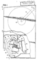
- the dispenser 10 of this invention is shown having a cabinet 12 adapted to be mounted at a convenient location for intending users of the paper toweling supplied from the rolled web material carried within the cabinet 12. A portion of the cabinet 12 is broken away to display the one-revolution stop mechanism and other components mounted within the cabinet 12.
- a roll R of flexible web material is mounted on a yoke 14, the yoke being pivoted at 16 to the backplate of the dispenser cabinet 12.
- Yoke 14 has a pair of yoke arms with cups 18 rotatably mounted at the outer ends of the yoke arms, these cups being inserted at each core end into the central tubular core of the towel roll R.
- the web W withdrawn from roll R is threaded counterclockwise around a pinchroller 20.
- the web then passes clockwise around the rearside of a feed roller 22 to pass counter-clockwise over an exit pinchroller 24.
- Pinch rollers 20 and 24 are pressed against the feed roller 22 by springs (not shown) with all rollers being supported by appropriate bearings (not shown) in the sideplates of the dispenser cabinet 12.
- the web then exits through opening 26 in cabinet 12 to be accessible to intending users of the paper toweling material coming from roll R.
- a tab length T of the toweling web W of about 3 inches will extend outside the dispenser beyond opening 26 to be available for grasping by the intending users of the web material. This preferred length T of web material is automatically fed from the dispenser 10 in conjunction with operation of the stop-mechanism to be described hereinafter.
- the feed roller 22 has an internal knife 30 which is mounted laterally offset from the rotational axis of feed roller 22. Knife 30 is supported within the feed roller to project through an opening (not shown) in the feed roller periphery to essentially severe the web material when it passes over the feed roller surface as the feed roller 22 makes a single revolution.
- the web material is thus perforated to leave only three uncut 1/4 inch long tabs connecting successive sheets in the web.
- This transverse perforating of the web material in cabinet 12 defines individual sheets which are of a length equal to the feed roller circumference so that the web W is formed with a row of perforations between one sheet and the next succeeding sheet.
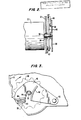
- Feed roller 22 is rotatably mounted by shaft 32 which extends through bearing 34 carried by the sidewall of cabinet 12 as shown on Figure 2.
- Shaft 32 extends outwardly beyond bearing 34 and has a feed wheel 36 fixedly secured to its outer end.
- the feed wheel 36 has a control tab 38 which cooperates with a stop-lever 40 to constitute the active component of the stop-mechanism as will be described hereinafter.
- Stop-lever 40 is pivotally mounted at 42 on one of the sideplates of the dispenser cabinet 12. This pivotal mounting of stop lever 40 disposes it between the feed wheel 36 and sideplate of the cabinet 12 as shown in Figure 2.
- the stop-lever is provided with a slot 44.
- This slot 44 enables the stop-lever 40 to pivot around pivotal mounting 42 with the slot being disposed to pass around shaft 32 during pivoting movements of the stop-lever, shaft 32 mounting both feed roller 22 and feed wheel 36.
- stop-lever 40 facing the surface of feed wheel 36 which carried control tab 38 is provided with a lift flange 46 and a stop flange 48.
- the feed roller 22 and feed wheel 36 rotate the control tab 38 into interengagement with lift flange 46 and stop flanges 48 to carry out the functioning of the stop mechanism.
- the lift flange 46 extends generally radially relative to the pivotal mounting 42 of lever 40. With the two flanges mounted on opposite sides of the slot 44, the stop flange 48 extends generally along one side of slot 44 to be generally perpendicular to the lift flange 46 and spaced from such flange by the width of slot 44.
- the spacing between the adjacent ends of flange 46 and flange 48 is slightly greater than the length of control tab 38, thereby leaving a small space 50 (see Figure 5) between the lift flange 46 and control tab 38 when tab 38 is pressed into abutting frictional engagement with the surface of stop flange 48.
- This surface of flange 48 is slightly curved toward the pivotal mounting 42 of stop lever 40 for a purpose which will be explained hereinafter.
- the stop lever 40 is also provided with a spring retainer 60.
- retainer 60 is in the form of a leaf spring with one end fixed at 62 in a groove formed in the surface of stop lever 40. This retainer 60 lies along the surface of lift flange 46 to cooperate with the control tab 38 when the tab has passed from beneath the lift flange 46 into frictional abutting engagement with stop flange 48, the leaf spring retainer 60 then preventing reverse rotation of feed wheel 36 and feed roller 22.
- stop-mechanism involves having stop flange 48 so located relative to the cutting knife 30 within the feed roller 22 that when control tab 38 engages with stop flange 48, the perforations on the towel web will have reached a point where tab T extends about 3 inches outside the dispenser as shown on Figure 1. As the intending user continues pulling toweling from the dispenser, the sudden stop when tab 34 engages stop flange 48 will cause the free uncut tabs along the perforations in the web to break off thus delivering a cut off sheet of toweling into the user's hands and leaving the exposed web tab T for the next user.
- the stop lever 40 not only stops the feed roller 22 from rotation but also (1) releases the feed roller for further rotation as soon as the web is broken off along the perforations, (2) keeps the stop engaged until the web is broken off and (3) accomplishes these functions no matter how slowly or fast the web is withdrawn from the dispenser.
- control tab 38 and stop flange 48 At the stop position, it will be noted that at the center of the mating surfaces of control tab 38 and stop flange 48, the angle between the lines extending toward the feed wheel axis of shaft 32 and the stop lever pivotal mounting 42 is 90°, thus preventing pressure applied by control tab 38 against stop flange 48 from moving the stop lever 40 either up or down. It should also be noted that as control tab 38 passes out from beneath the lift flange 46 a small space 50 separates the control tab and lift flange to allow the stop lever to drop.
- the leaf spring retainer 60 partially recessed into the face of stop lever 40 as shown in Figure 8, protrudes out of this recess at its outer end. This upwardly protruding end thus prevents control tab 38 from bouncing back under the lift flange 46 once the control tab hits the stop flange 48. Should the control tab be able to bounce back beneath the lift flange 46, such would prevent the stop lever 40 from dropping and thereupon releasing the feed roller and feed wheel for rotation.
- control tab 38 and stop flange 48 are pressed together by the existence of a pull on the web, the friction between these components prevents the stop lever from dropping.
- such pressure is immediately released such as to allow the stop lever 40 to drop by gravity to the position as shown in Figure 6.
- the curve of the mating surface of stop flange 48 is so designed that as the stop lever drops, the surface of flange 48 moves slightly away from control tab 38 on the feed wheel 36 to prevent any interference between the control tab and stop flange while the stop lever 40 is dropping to the position shown on Figure 6 where the slot 44 again rests on the shaft 32.
- an extra lift of 1.2 inches provides a timing interval of 2/3 of a second. Due to the short space 50 (see Figure 5) the towel web can be pulled out as slowly as 1-1/2 inches per second and still be stopped by the stop lever. With a 9 inch long towel, this means that it can be pulled out as slowly as over a 6 second time interval and still be stopped.
- the design thus provides adequate waste restriction without need for complicated timing mechanisms. It should also be noted that depending upon the speed at which the towel is pulled from dispenser 10, control tab 38 will strike stop flange 48 at varying points along the surface of stop flange 48.
Landscapes
- Health & Medical Sciences (AREA)
- Public Health (AREA)
- Unwinding Webs (AREA)
- Toilet Supplies (AREA)
- Replacement Of Web Rolls (AREA)
Applications Claiming Priority (2)
| Application Number | Priority Date | Filing Date | Title |
|---|---|---|---|
| US06/838,799 US4732306A (en) | 1986-03-12 | 1986-03-12 | One-revolution stop mechanism and dispensing method for rolled web dispensers |
| US838799 | 1986-03-12 |
Publications (1)
| Publication Number | Publication Date |
|---|---|
| EP0236709A1 true EP0236709A1 (de) | 1987-09-16 |
Family
ID=25278071
Family Applications (1)
| Application Number | Title | Priority Date | Filing Date |
|---|---|---|---|
| EP19870100917 Withdrawn EP0236709A1 (de) | 1986-03-12 | 1987-01-23 | Umdrehungsstoppmechanismus und Verfahren zum Ausgeben für Spender von einem gewickelten Band |
Country Status (9)
| Country | Link |
|---|---|
| US (1) | US4732306A (de) |
| EP (1) | EP0236709A1 (de) |
| JP (1) | JPS6359919A (de) |
| KR (1) | KR870008561A (de) |
| BR (1) | BR8701133A (de) |
| DK (1) | DK124487A (de) |
| FI (1) | FI871061A7 (de) |
| IE (1) | IE870145L (de) |
| NO (1) | NO871000L (de) |
Cited By (6)
| Publication number | Priority date | Publication date | Assignee | Title |
|---|---|---|---|---|
| WO2000073187A1 (de) * | 1999-05-31 | 2000-12-07 | Kel Development B.V. | Bandspender |
| WO2011130767A1 (de) * | 2010-04-23 | 2011-10-27 | Hans Georg Hagleitner | Papierspender |
| CN104755001A (zh) * | 2012-10-26 | 2015-07-01 | Sca卫生用品公司 | 分离单元和包括分离单元的分配器 |
| US10058221B2 (en) | 2012-10-26 | 2018-08-28 | Sca Hygiene Products Ab | Dispenser |
| US10390664B2 (en) | 2012-10-26 | 2019-08-27 | Essity Hygiene And Health Aktiebolag | Separation unit and a dispenser comprising a separation unit |
| US11206956B2 (en) | 2014-04-28 | 2021-12-28 | Essity Hygiene And Health Aktiebolag | Dispenser |
Families Citing this family (17)
| Publication number | Priority date | Publication date | Assignee | Title |
|---|---|---|---|---|
| US5048386A (en) * | 1989-10-27 | 1991-09-17 | Georgia-Pacific Corporation | Feed mechanism for flexible sheet material dispensers |
| US5078033A (en) * | 1990-11-13 | 1992-01-07 | Georgia-Pacific Corporation | Flexible sheet material dispenser |
| IE80725B1 (en) * | 1991-02-26 | 1998-12-30 | Georgia Pacific Corp | Method and apparatus for dispensing flexible sheet material |
| US5202617A (en) * | 1991-10-15 | 1993-04-13 | Norvik Technologies Inc. | Charging station for electric vehicles |
| US5558302A (en) * | 1995-02-07 | 1996-09-24 | Georgia-Pacific Corporation | Flexible sheet material dispenser with automatic roll transferring mechanism |
| US5660636A (en) * | 1995-03-21 | 1997-08-26 | Shangold; Gary A. | Apparatus for housing and dispensing hygienic applicators |
| FR2739545B1 (fr) * | 1995-10-10 | 1997-12-26 | Maurice Granger | Appareil distributeur de materiau d'essuyage avec dispositif de chargement d'un rouleau de reserve |
| USD417109S (en) | 1998-02-02 | 1999-11-30 | Fort James Corporation | Sheet material dispenser |
| US6228454B1 (en) | 1998-02-02 | 2001-05-08 | Fort James Corporation | Sheet material having weakness zones and a system for dispensing the material |
| US6321963B1 (en) | 1998-02-02 | 2001-11-27 | Fort James Corporation | Sheet material dispensing apparatus and method |
| US6102269A (en) * | 1999-06-21 | 2000-08-15 | Bay West Paper Corporation | Towel dispenser with metering mechanism |
| US6591727B1 (en) | 2000-02-25 | 2003-07-15 | Kimberly-Clark Worldwide, Inc. | Recessed apparatus for cutting and dispensing a web of rolled material |
| USD441231S1 (en) | 2000-05-01 | 2001-05-01 | Kimberly-Clark Worldwide, Inc. | Paper towel dispenser |
| US6766977B2 (en) * | 2001-02-27 | 2004-07-27 | Georgia-Pacific Corporation | Sheet material dispenser with perforation sensor and method |
| US6607160B2 (en) | 2001-07-30 | 2003-08-19 | Kimberly-Clark Worldwide | Easy loading dispenser |
| US20040083871A1 (en) * | 2002-07-12 | 2004-05-06 | Mosher Paul S. | Twist-tie dispenser |
| BR112022024815A2 (pt) | 2020-06-25 | 2023-01-17 | Kimberly Clark Co | Dispositivo de distribuição com suporte de montagem |
Citations (3)
| Publication number | Priority date | Publication date | Assignee | Title |
|---|---|---|---|---|
| US2886226A (en) * | 1956-03-12 | 1959-05-12 | George X Batlas | Paper towel dispenser |
| USRE28911E (en) * | 1971-01-06 | 1976-07-20 | Georgia-Pacific Corporation | Dispenser for flexible sheet material and a perforating mechanism adapted to be used therein |
| EP0011262A1 (de) * | 1978-11-20 | 1980-05-28 | Apura GmbH + Co. PWA Einmalhandtücher | Vorrichtung zur Ausgabe von Papierschnitten vorgegebener Länge |
Family Cites Families (11)
| Publication number | Priority date | Publication date | Assignee | Title |
|---|---|---|---|---|
| US28911A (en) * | 1860-06-26 | Improvement in air-engines | ||
| US1224224A (en) * | 1915-12-17 | 1917-05-01 | Robert N Shelley | Towel-paper holder. |
| US2067760A (en) * | 1934-10-05 | 1937-01-12 | Leo M Harvey | Towel cabinet |
| US2183187A (en) * | 1939-03-02 | 1939-12-12 | Robert J Freeman | Control device for dispensing mechanism |
| US2826373A (en) * | 1955-07-05 | 1958-03-11 | Franics H Schwartz | Intermittent motion mechanism |
| US2892579A (en) * | 1955-11-25 | 1959-06-30 | Bernard C Hubers | Towel cabinet |
| US3017131A (en) * | 1958-06-23 | 1962-01-16 | Philip A Wooster | Paper towel dispenser |
| US3575328A (en) * | 1969-01-24 | 1971-04-20 | Georgia Pacific Corp | Dispenser for flexible sheet material and a perforating mechanism adapted to be used therein |
| FR2332215A1 (fr) * | 1975-11-19 | 1977-06-17 | Granger Maurice | Appareil de coupe et de distribution simultanees de bandes de materiaux enroules |
| DE2639810C3 (de) * | 1976-09-03 | 1980-03-20 | Pwa Papierwerke Waldhof-Aschaffenburg Ag, 8000 Muenchen | Verfahren und Vorrichtung zum Abziehen eines Materialbahnabschnittes vorgegebener Länge von einer Vorratsrolle |
| US4073422A (en) * | 1977-01-24 | 1978-02-14 | Service Sequence Systems | Ticket dispenser |
-
1986
- 1986-03-12 US US06/838,799 patent/US4732306A/en not_active Expired - Lifetime
-
1987
- 1987-01-20 IE IE870145A patent/IE870145L/xx unknown
- 1987-01-23 EP EP19870100917 patent/EP0236709A1/de not_active Withdrawn
- 1987-03-11 NO NO871000A patent/NO871000L/no unknown
- 1987-03-11 DK DK124487A patent/DK124487A/da not_active Application Discontinuation
- 1987-03-11 FI FI871061A patent/FI871061A7/fi not_active Application Discontinuation
- 1987-03-12 BR BR8701133A patent/BR8701133A/pt unknown
- 1987-03-12 KR KR870002179A patent/KR870008561A/ko not_active Withdrawn
- 1987-03-12 JP JP62057868A patent/JPS6359919A/ja active Pending
Patent Citations (3)
| Publication number | Priority date | Publication date | Assignee | Title |
|---|---|---|---|---|
| US2886226A (en) * | 1956-03-12 | 1959-05-12 | George X Batlas | Paper towel dispenser |
| USRE28911E (en) * | 1971-01-06 | 1976-07-20 | Georgia-Pacific Corporation | Dispenser for flexible sheet material and a perforating mechanism adapted to be used therein |
| EP0011262A1 (de) * | 1978-11-20 | 1980-05-28 | Apura GmbH + Co. PWA Einmalhandtücher | Vorrichtung zur Ausgabe von Papierschnitten vorgegebener Länge |
Cited By (13)
| Publication number | Priority date | Publication date | Assignee | Title |
|---|---|---|---|---|
| WO2000073187A1 (de) * | 1999-05-31 | 2000-12-07 | Kel Development B.V. | Bandspender |
| US6659322B1 (en) * | 1999-05-31 | 2003-12-09 | Kel Development B.V. | Tape dispenser |
| WO2011130767A1 (de) * | 2010-04-23 | 2011-10-27 | Hans Georg Hagleitner | Papierspender |
| US10058221B2 (en) | 2012-10-26 | 2018-08-28 | Sca Hygiene Products Ab | Dispenser |
| CN104755001B (zh) * | 2012-10-26 | 2017-08-08 | Sca卫生用品公司 | 分离单元和包括分离单元的分配器 |
| US9999325B2 (en) | 2012-10-26 | 2018-06-19 | Sca Hygiene Products Ab | Separation unit and a dispenser comprising a separation unit |
| CN104755001A (zh) * | 2012-10-26 | 2015-07-01 | Sca卫生用品公司 | 分离单元和包括分离单元的分配器 |
| US10390664B2 (en) | 2012-10-26 | 2019-08-27 | Essity Hygiene And Health Aktiebolag | Separation unit and a dispenser comprising a separation unit |
| US10568471B2 (en) | 2012-10-26 | 2020-02-25 | Essity Hygiene And Health Aktiebolag | Separation unit and a dispenser comprising a separation unit |
| US10842329B2 (en) | 2012-10-26 | 2020-11-24 | Essity Hygiene And Health Aktiebolag | Separation unit and a dispenser comprising a separation unit |
| US11166604B2 (en) | 2012-10-26 | 2021-11-09 | Essity Hygiene And Health Aktiebolag | Separation unit and a dispenser comprising a separation unit |
| US11871877B2 (en) | 2012-10-26 | 2024-01-16 | Essity Hygiene And Health Aktiebolag | Separation unit and a dispenser comprising a separation unit |
| US11206956B2 (en) | 2014-04-28 | 2021-12-28 | Essity Hygiene And Health Aktiebolag | Dispenser |
Also Published As
| Publication number | Publication date |
|---|---|
| JPS6359919A (ja) | 1988-03-15 |
| IE870145L (en) | 1987-09-12 |
| NO871000D0 (no) | 1987-03-11 |
| US4732306A (en) | 1988-03-22 |
| KR870008561A (ko) | 1987-10-19 |
| DK124487D0 (da) | 1987-03-11 |
| BR8701133A (pt) | 1988-01-05 |
| FI871061A0 (fi) | 1987-03-11 |
| NO871000L (no) | 1987-09-14 |
| FI871061A7 (fi) | 1987-09-13 |
| DK124487A (da) | 1987-09-13 |
Similar Documents
| Publication | Publication Date | Title |
|---|---|---|
| US4732306A (en) | One-revolution stop mechanism and dispensing method for rolled web dispensers | |
| US6826991B1 (en) | Web transfer mechanism for flexible sheet dispenser | |
| US6314850B1 (en) | Paper toweling dispensing system | |
| US4340195A (en) | Dispenser for rolled flexible sheet material | |
| US8555761B2 (en) | Paper sheet material dispenser apparatus | |
| US10299638B2 (en) | Dispenser | |
| US4203562A (en) | Flexible sheet material dispensing of rolls in succession | |
| CA2092585C (en) | Perforated paper towel dispenser | |
| US4307639A (en) | Multiple wound roll dispenser for flexible sheet material | |
| US4807824A (en) | Paper roll towel dispenser | |
| US20100102101A1 (en) | Paper toweling dispenser apparatus | |
| US5078033A (en) | Flexible sheet material dispenser | |
| US6224010B1 (en) | Apparatus and method for dispensing paper toweling from a roll of paper toweling | |
| EP1877230B1 (de) | Papierhandtuchausgabevorrichtung | |
| US4432261A (en) | Severing web plies in multiple roll material dispensers | |
| US4067509A (en) | Paper towel dispenser and transfer mechanism | |
| IE47047B1 (en) | A device for dispensing sheets of web material of predetermined length | |
| US2051242A (en) | Paper towel dispensing apparatus | |
| CA1115668A (en) | Multiple wound roll dispenser and cutter mechanism for use therein | |
| US4189077A (en) | Sheet material dispensing device | |
| WO2013169438A1 (en) | Paper sheet material dispenser apparatus | |
| US5410930A (en) | Low operating force stop mechanism and dispensing method for rolled web dispensers | |
| US2206979A (en) | Paper unit dispensing device | |
| EP1412143B1 (de) | Abgabesystem für papierhandtücher | |
| EP0339798A1 (de) | Spender für Rollenmaterial |
Legal Events
| Date | Code | Title | Description |
|---|---|---|---|
| PUAI | Public reference made under article 153(3) epc to a published international application that has entered the european phase |
Free format text: ORIGINAL CODE: 0009012 |
|
| AK | Designated contracting states |
Kind code of ref document: A1 Designated state(s): CH DE FR GB IT LI NL SE |
|
| 17P | Request for examination filed |
Effective date: 19880107 |
|
| 17Q | First examination report despatched |
Effective date: 19881031 |
|
| STAA | Information on the status of an ep patent application or granted ep patent |
Free format text: STATUS: THE APPLICATION IS DEEMED TO BE WITHDRAWN |
|
| 18D | Application deemed to be withdrawn |
Effective date: 19890311 |
|
| RIN1 | Information on inventor provided before grant (corrected) |
Inventor name: JESPERSEN, PAUL W. |