EP0236716A2 - Bague circulaire de blindage et de mise à la terre pour un connecteur électrique - Google Patents
Bague circulaire de blindage et de mise à la terre pour un connecteur électrique Download PDFInfo
- Publication number
- EP0236716A2 EP0236716A2 EP87101184A EP87101184A EP0236716A2 EP 0236716 A2 EP0236716 A2 EP 0236716A2 EP 87101184 A EP87101184 A EP 87101184A EP 87101184 A EP87101184 A EP 87101184A EP 0236716 A2 EP0236716 A2 EP 0236716A2
- Authority
- EP
- European Patent Office
- Prior art keywords
- groove
- ring portion
- ring
- fingers
- shell
- Prior art date
- Legal status (The legal status is an assumption and is not a legal conclusion. Google has not performed a legal analysis and makes no representation as to the accuracy of the status listed.)
- Withdrawn
Links
Images

Classifications
-
- H—ELECTRICITY
- H01—ELECTRIC ELEMENTS
- H01R—ELECTRICALLY-CONDUCTIVE CONNECTIONS; STRUCTURAL ASSOCIATIONS OF A PLURALITY OF MUTUALLY-INSULATED ELECTRICAL CONNECTING ELEMENTS; COUPLING DEVICES; CURRENT COLLECTORS
- H01R13/00—Details of coupling devices of the kinds covered by groups H01R12/70 or H01R24/00 - H01R33/00
- H01R13/648—Protective earth or shield arrangements on coupling devices, e.g. anti-static shielding
- H01R13/658—High frequency shielding arrangements, e.g. against EMI [Electro-Magnetic Interference] or EMP [Electro-Magnetic Pulse]
- H01R13/6581—Shield structure
- H01R13/6582—Shield structure with resilient means for engaging mating connector
- H01R13/6583—Shield structure with resilient means for engaging mating connector with separate conductive resilient members between mating shield members
- H01R13/6584—Shield structure with resilient means for engaging mating connector with separate conductive resilient members between mating shield members formed by conductive elastomeric members, e.g. flat gaskets or O-rings
Definitions
- This invention relates to a circumferential grounding and shielding ring for an electrical connector assembly and, more particularly, to a connector assembly having an improved solderless arrangement for mounting the shielding ring about a connector shell.
- a grounding and shielding ring for connector shells is typically cup-shaped and mounted on a plug shell with deflectable spring fingers from the shielding ring being adapted to be biased against the outer periphery of a mating receptacle shell.
- the ring is integrally stamped from a metal sheet and formed by rolling the edges of the sheet into the cup-shape.
- U.S patent 4,423,919 and 4,428,639 disclose solderless approaches for mounting a grounding ring to a connector shell. While many solderless mounting arrangements perform well in some environments, other approaches provide a grounding ring mounting which is too sensitive to tolerance variations in order to be dependable. A split ground ring requires attention to the bias force of the spring fingers.
- a loosely fitted ground ring will increase shell-to-shell resistance.
- the spring fingers deflect radially in relation to the connector axis and impose a stress at the bottom of the slots. This can result in cracks in the grounding ring and thereby result in adverse shell-to-shell resistance, and reduce spring finger forces which could break down oxides which form and resist good electrical circuit relation being established. Further, once a crack develops, the stopping point of the crack cannot be stopped. As a result and during vibration, it has been found that a complete break can occur in an already split grounding ring, and the separated ring portions can be driven radially outward from their mounting in an annular groove around the plug shell.
- an electrical connector includes a pair of mating electrical connector members having telescopically assembled conductive shells to provide overlapping adjacent circumferential surfaces with one of the surfaces being provided with a continuous circumferential groove of predetermined axial dimension.
- a shielding and grounding ring is mounted in the groove, the ring comprising a flat ring portion extending substantially continuously around the annular groove and having an inner and an outer edge with the inner edge being disposed in the groove.
- a set of radially deflectable spring fingers are integral with the outer edge each extending longitudinally therefrom along the connector axis and terminating in a deflectable free end portion adapted to engage the other of the surfaces. The fingers are angularly spaced whereby to describe a set of axially extending slots
- the shielding and grounding ring is characterized by a circumferential lip extending axially from the inner edge and in electrical circuit contact relation substantially continuously 360° around and within the groove and the slots defining each finger undergoing approximately 90° change in direction so as to extend into the ring portion.
- the mounting means includes a compression ring being plastically deformed to press the circumferential lip radially inward against the circumferential surface of the annular groove and the ring portion axially forward and against a rearwardly facing axial wall defined by the groove.
- FIGURE 1 shows a partial sectional view of a receptacle and a plug electrical connector subassembly 10,20 about to be mated.
- Each of the connector subassemblies are generally comprised of a cylindrical shell 12,22 of conductive material with a forward portion 24 of the plug shell 22 being sized to telescopically interfit within a forward portion 14 of the receptacle shell 12 such that when mated respective outer surfaces are overlapping.
- the end face of the receptacle makes abutting contact with a moisture seal (not shown) extending around the plug shell.
- the connector subassemblies have electrical contacts which engage upon axial mating of the connector shells along a center axis thereof.
- a plurality of socket-type contacts 26 are positioned in the plug shell for mating engagement with a like plurality of pin-type contacts 16 in the receptacle shell, each of the contacts being positioned in dielectric insulators mounted within the respective shells.
- a coupling nut 30 is captivated for rotation on the plug shell such that a helical groove 32 on in inner wall of the nut threadably engages with a bayonet pin 34 on the outer surface of the receptacle shell.
- a keyway 13 in the receptacle shell 12 receives a polarizing rib 23 on the plug shell to prevent relative rotation between the connector shells when the coupling nut 30 rotates to draw the shells axially together along the central axis.
- a cup-shaped grounding and shielding ring 40 is mounted onto the plug shell in a continuous annular groove 21 adjacent to a radial flange 25.
- a compression ring 50 is plastically deformed into the annular groove to non-removably retain the shielding ring.
- FIGURE 2 shows detail of the two rings.
- the shield ring 40 is cup-shaped, split, has a slotted skirt, and is integrally formed of a conductive material whereby to ground the mated assembly of connector shells.
- the ring 40 comprises a flat annular ring portion 42 having forward and rearward faces 45,47, an inner edge 41 and an outer edge 43, and a plurality of resilient, convexly-curved, spring fingers 44 each extending from the outer edge and integrally formed therewith.
- the inner edge defines an opening (i.e., has an inner diameter) sized to allow the ring portion to be slidably clearance fit over the rearward end portion of the plug shell.
- Extending axially rearward from the inner edge of the ring portion is a continuous circumferential lip (i.e., annular flange) 48 having an axial dimension sized to fit the annular groove 21.
- Each of the fingers 44 are defined by a longitudinally extending slot 46, the slot undergoing a 90° change in direction so as to terminate radially inward from the locus of finger inner surfaces and be within the ring portion.
- the compression ring 50 is not split and is assembled over the rearward end portion of the plug shell.
- the compression ring is comprised of an electrically conductive material and is mounted to the plug shell so that a forward ring face 52 thereof will uniformly butt against the rearward face 47 of the flat ring portion 42, and an inner circumferential face 53 thereof (i.e., the opening) is circumposed around the annular groove.
- the compression ring is made of electrically conductive material since the compression ring is included in the ground path of the shielded connector. The higher the electrical conductivity of the material used to form the compression ring the better. For details, the reader is refered to USP 4,428,639, incorporated herein by reference.
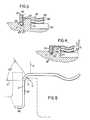
- Figure 3 shows the shielding and grounding ring 40 disposed in the annular groove 21 of the plug shell 22 with the forward face 45 of ring portion 42 abutting the rearward face 27 of radial flange 25.
- Lip 48 substantially circumferentially closes about the circumferential surface forming the annular groove 21.
- the slots 46 in the configuration shown are disposed substantially at or radially inward from the top circumferential face of the radial flange.
- the compression ring 50 is positioned for inward radial compression into the annular groove and about the circumferential lip 48.
- FIGURE 4 shows the assembled relation of the shielding and grounding ring 40 and the compression ring 50 in the annular groove 21.
- the grounding ring is such that the forward face 45 and the circumferential lip 48 are in substantial 360° abutment with the rearward face 27 and circumferential periphery of annular groove 21.
- the compression ring assures positive retention of the grounding ring as a result of engagement with the lip 48 and good electrical circuit path characteristics by the 360° engagement with the plug shell.
- FIGURE 5 shows an enlarged view of the shielding and grounding ring 40 mounted within the annular groove.
- the spring fingers 44 extend longitudinally from the outer edge of the ring portion 42 from which they are integrally connected and the slots 46 undergo approximately a 90° change in direction to terminate in respective roots on the ring portion.
- the ring portion has its forward face in firm fitting relation about the rearward face of the radial flange and the circumferential lip 48 in firm fitting relation substantially 360° about the base of the annular groove.
- the fingers terminations preferably should be formed by a generous, generally circular radius as shown by the position "C". The smaller the bend radius the more likely it is believed that cracks will form.
- a slot 46 should preferably terminate in the ring portion 42 after having undergone a 90° change in direction and lie in a plane which is concentric with and passes through the position "C". As the slot terminus (preferably defined by an imaginary radius line “A”) is moved from ring portion 42 and positioned closer to the spring fingers (such as defined by an imaginary radius line "B”) the more likely it is that cracks will form in the spring fingers.
- the slots 46 should not terminate at a position greater than 50° from radius "A”. Further, the slots 46 should not terminate at ring portion locations on the ring portion downwardly from the radius line "A" (e g., such as shown by point "D") since it is believed that this location would tend to adversely weaken spring finger forces.
- the spring fingers should, preferably, have an angular extension "E" (see FIGURES 3 and 4) much greater than the angular separation "S" defined by the slots 46.
Landscapes
- Details Of Connecting Devices For Male And Female Coupling (AREA)
- Multi-Conductor Connections (AREA)
- Connector Housings Or Holding Contact Members (AREA)
Applications Claiming Priority (2)
| Application Number | Priority Date | Filing Date | Title |
|---|---|---|---|
| US826534 | 1986-02-06 | ||
| US06/826,534 US4655532A (en) | 1986-02-06 | 1986-02-06 | Circumferential grounding and shielding ring for an electrical connector |
Publications (2)
| Publication Number | Publication Date |
|---|---|
| EP0236716A2 true EP0236716A2 (fr) | 1987-09-16 |
| EP0236716A3 EP0236716A3 (fr) | 1988-09-21 |
Family
ID=25246805
Family Applications (1)
| Application Number | Title | Priority Date | Filing Date |
|---|---|---|---|
| EP87101184A Withdrawn EP0236716A3 (fr) | 1986-02-06 | 1987-01-28 | Bague circulaire de blindage et de mise à la terre pour un connecteur électrique |
Country Status (3)
| Country | Link |
|---|---|
| US (1) | US4655532A (fr) |
| EP (1) | EP0236716A3 (fr) |
| JP (1) | JPS62217582A (fr) |
Cited By (2)
| Publication number | Priority date | Publication date | Assignee | Title |
|---|---|---|---|---|
| EP1029926A1 (fr) * | 1999-02-08 | 2000-08-23 | Kyowa Hakko Kogyo Co., Ltd. | Procédé de préparation des nucléotides de purine |
| EP4059793A1 (fr) | 2021-03-17 | 2022-09-21 | Sherpa Autodiagnostik GmbH | Dispositif d'essai de frein pour un véhicule pourvu d'au moins un essieu pouvant être entraîné et procédé |
Families Citing this family (22)
| Publication number | Priority date | Publication date | Assignee | Title |
|---|---|---|---|---|
| US4932900A (en) * | 1986-11-03 | 1990-06-12 | Amphenol Corporation | Electrical connector with rear removable circuit elements |
| JPH043428Y2 (fr) * | 1987-05-18 | 1992-02-03 | ||
| US4790765A (en) * | 1987-10-05 | 1988-12-13 | Hubbell Incorporated | Connector shunt structure |
| ATE141028T1 (de) * | 1987-10-15 | 1996-08-15 | Palco Connector Inc | Hochfrequenzkoaxialverbinder mit gleicher impedanz |
| US4917630A (en) * | 1987-10-15 | 1990-04-17 | The Phoenix Company Of Chicago, Inc. | Constant impedance high frequency coaxial connector |
| US4874337A (en) * | 1988-11-23 | 1989-10-17 | Amp Incorporated | Method of mounting a replaceable EMI spring strip |
| US5109424A (en) * | 1989-01-19 | 1992-04-28 | Koss Corporation | Stereo headphones with plug, receptacle and securing plates |
| FR2670615B1 (fr) * | 1990-12-18 | 1993-02-19 | Radiall Sa | Connecteur electrique coaxial. |
| FR2684494B1 (fr) * | 1991-11-29 | 1995-07-07 | Souriau & Cie | Bracelet de blindage pour connecteurs electriques, et connecteurs equipes d'un tel bracelet. |
| IT1275681B1 (it) * | 1993-12-04 | 1997-10-17 | Interconnectron Gmbh | Connettore da innesto elettrico con dispositivo di contatto per la schermatura emv del cavo. |
| US5788538A (en) | 1996-07-31 | 1998-08-04 | Berg Technology, Inc. | Shield for modular jack |
| TW561120B (en) * | 2001-05-25 | 2003-11-11 | Primax Electronics Ltd | Cigarette lighter plug which can be inserted into sockets of different dimensions |
| US7555540B2 (en) * | 2003-06-25 | 2009-06-30 | Microsoft Corporation | Media foundation media processor |
| US20060013000A1 (en) * | 2004-07-16 | 2006-01-19 | Osram Sylvania Inc. | Flat mount for light emitting diode source |
| DE102006012337B3 (de) * | 2006-03-17 | 2007-11-29 | Amphenol-Tuchel Electronics Gmbh | Elektrischer Steckverbinder |
| US7481676B2 (en) * | 2006-08-30 | 2009-01-27 | Tyco Electronics Corporation | Electrical connector with ESD protection |
| GB2453788A (en) * | 2007-10-19 | 2009-04-22 | Itt Mfg Enterprises Inc | Electrical connector having resilient electrical connection to conductive sleeve |
| US8025518B2 (en) * | 2009-02-24 | 2011-09-27 | Corning Gilbert Inc. | Coaxial connector with dual-grip nut |
| EP3306756B1 (fr) * | 2016-10-07 | 2020-04-15 | TE Connectivity Germany GmbH | Connecteur enfichable |
| DE102018130304B4 (de) * | 2018-11-29 | 2020-07-16 | Te Connectivity Germany Gmbh | Kontakteinrichtung und System |
| DE102021102570A1 (de) * | 2021-02-04 | 2022-08-04 | Carl Freudenberg Kg | Erdungsring und Anordnung, die einen solchen Erdungsring umfasst |
| DE102024103824A1 (de) * | 2024-02-12 | 2025-08-14 | Harting Electric Stiftung & Co. Kg | Rundsteckverbinder mit Schirmanbindung |
Family Cites Families (8)
| Publication number | Priority date | Publication date | Assignee | Title |
|---|---|---|---|---|
| US4239318A (en) * | 1979-07-23 | 1980-12-16 | International Telephone And Telegraph Corporation | Electrical connector shield |
| GB2073503B (en) * | 1980-03-27 | 1983-12-21 | Thorn Elect Components Ltd | Contact spring for an electrical connector |
| US4326768A (en) * | 1980-06-02 | 1982-04-27 | The Bendix Corporation | Electrical connector grounding strap connection |
| US4423919A (en) * | 1982-04-05 | 1984-01-03 | The Bendix Corporation | Electrical connector |
| US4428639A (en) * | 1982-04-05 | 1984-01-31 | The Bendix Corporation | Electrical connector |
| US4470657A (en) * | 1982-04-08 | 1984-09-11 | International Telephone & Telegraph Corporation | Circumferential grounding and shielding spring for an electrical connector |
| GB2127626B (en) * | 1982-04-23 | 1986-02-19 | Allied Corp | A spring structure and an electrical connector with an electromagnetic shielding system |
| US4512623A (en) * | 1984-02-03 | 1985-04-23 | Allied Corporation | Electrical connector assembly having means for shielding electromagnetic interference |
-
1986
- 1986-02-06 US US06/826,534 patent/US4655532A/en not_active Expired - Lifetime
-
1987
- 1987-01-28 EP EP87101184A patent/EP0236716A3/fr not_active Withdrawn
- 1987-02-05 JP JP62023742A patent/JPS62217582A/ja active Pending
Cited By (2)
| Publication number | Priority date | Publication date | Assignee | Title |
|---|---|---|---|---|
| EP1029926A1 (fr) * | 1999-02-08 | 2000-08-23 | Kyowa Hakko Kogyo Co., Ltd. | Procédé de préparation des nucléotides de purine |
| EP4059793A1 (fr) | 2021-03-17 | 2022-09-21 | Sherpa Autodiagnostik GmbH | Dispositif d'essai de frein pour un véhicule pourvu d'au moins un essieu pouvant être entraîné et procédé |
Also Published As
| Publication number | Publication date |
|---|---|
| EP0236716A3 (fr) | 1988-09-21 |
| US4655532A (en) | 1987-04-07 |
| JPS62217582A (ja) | 1987-09-25 |
Similar Documents
| Publication | Publication Date | Title |
|---|---|---|
| US4655532A (en) | Circumferential grounding and shielding ring for an electrical connector | |
| EP0001701B1 (fr) | Connecteur électrique terminant un câble coaxial | |
| US4932897A (en) | Connector for an electrical signal transmitting cable | |
| US4531790A (en) | Electrical connector grounding ring | |
| US5021010A (en) | Soldered connector for a shielded coaxial cable | |
| US6024609A (en) | Outer contact spring | |
| US4938718A (en) | Cylindrical connector keying means | |
| CA1170736A (fr) | Connecteur electrique | |
| US4374606A (en) | Dielectric plug for a coaxial connector | |
| US4072386A (en) | Solid shell phonoconnectors | |
| EP0326447A2 (fr) | Alvéole de contact d'un connecteur électrique | |
| JPH0119634B2 (fr) | ||
| JPS6318840B2 (fr) | ||
| WO1985004766A1 (fr) | Contact de douille cylindrique capable d'exercer une force de contact elevee et necessitant une faible force d'appariage | |
| EP0152748A1 (fr) | Un assemblage de connexion électrique ayant des dispositifs de blindage contre les interférences électromagnétiques | |
| EP0273269B1 (fr) | Fiche de connecteur | |
| EP0592519A1 (fr) | Système de borne de raccordement à broches électrique et électronique, et à double usage | |
| US6007364A (en) | Guide post assembly | |
| US5063659A (en) | Method of joining a soldered connector to a shielded coaxial cable | |
| US5061207A (en) | Connector for a shielded coaxial cable | |
| EP0052980A2 (fr) | Système à éléments pour un assemblage d'un connecteur coaxial | |
| GB2066591A (en) | Electrical connector shell and method of making same | |
| EP0917243A3 (fr) | Borne de connexion destinée à être fixée sur une surface métallique | |
| CA2225602C (fr) | Connecteur et ensemble de connexion | |
| US12580102B2 (en) | Cap assembly for an electrical pass-through |
Legal Events
| Date | Code | Title | Description |
|---|---|---|---|
| PUAI | Public reference made under article 153(3) epc to a published international application that has entered the european phase |
Free format text: ORIGINAL CODE: 0009012 |
|
| AK | Designated contracting states |
Kind code of ref document: A2 Designated state(s): DE FR GB IT |
|
| PUAL | Search report despatched |
Free format text: ORIGINAL CODE: 0009013 |
|
| AK | Designated contracting states |
Kind code of ref document: A3 Designated state(s): DE FR GB IT |
|
| 17P | Request for examination filed |
Effective date: 19890309 |
|
| RAP1 | Party data changed (applicant data changed or rights of an application transferred) |
Owner name: AMPHENOL CORPORATION |
|
| 17Q | First examination report despatched |
Effective date: 19910708 |
|
| STAA | Information on the status of an ep patent application or granted ep patent |
Free format text: STATUS: THE APPLICATION IS DEEMED TO BE WITHDRAWN |
|
| 18D | Application deemed to be withdrawn |
Effective date: 19911119 |
|
| RIN1 | Information on inventor provided before grant (corrected) |
Inventor name: HILLIS, FRANK MARSC/O ALLIED CORPORATION Inventor name: BRUSH, ROBERT WILLIAM, SR.C/O ALLIED CORPORATION |