EP0236755B1 - Dispositif de détection d'une interruption dans un espace situé entre l'émetteur et le récepteur d'un signal lumineux émis d'au moins un émetteur - Google Patents
Dispositif de détection d'une interruption dans un espace situé entre l'émetteur et le récepteur d'un signal lumineux émis d'au moins un émetteur Download PDFInfo
- Publication number
- EP0236755B1 EP0236755B1 EP87101640A EP87101640A EP0236755B1 EP 0236755 B1 EP0236755 B1 EP 0236755B1 EP 87101640 A EP87101640 A EP 87101640A EP 87101640 A EP87101640 A EP 87101640A EP 0236755 B1 EP0236755 B1 EP 0236755B1
- Authority
- EP
- European Patent Office
- Prior art keywords
- receiver
- transmitters
- transmitter
- signals
- light
- Prior art date
- Legal status (The legal status is an assumption and is not a legal conclusion. Google has not performed a legal analysis and makes no representation as to the accuracy of the status listed.)
- Expired - Lifetime
Links
Images

Classifications
-
- H—ELECTRICITY
- H03—ELECTRONIC CIRCUITRY
- H03K—PULSE TECHNIQUE
- H03K17/00—Electronic switching or gating, i.e. not by contact-making and –breaking
- H03K17/94—Electronic switching or gating, i.e. not by contact-making and –breaking characterised by the way in which the control signals are generated
- H03K17/941—Electronic switching or gating, i.e. not by contact-making and –breaking characterised by the way in which the control signals are generated using an optical detector
- H03K17/943—Electronic switching or gating, i.e. not by contact-making and –breaking characterised by the way in which the control signals are generated using an optical detector using a plurality of optical emitters or detectors, e.g. keyboard
-
- F—MECHANICAL ENGINEERING; LIGHTING; HEATING; WEAPONS; BLASTING
- F16—ENGINEERING ELEMENTS AND UNITS; GENERAL MEASURES FOR PRODUCING AND MAINTAINING EFFECTIVE FUNCTIONING OF MACHINES OR INSTALLATIONS; THERMAL INSULATION IN GENERAL
- F16P—SAFETY DEVICES IN GENERAL; SAFETY DEVICES FOR PRESSES
- F16P3/00—Safety devices acting in conjunction with the control or operation of a machine; Control arrangements requiring the simultaneous use of two or more parts of the body
- F16P3/12—Safety devices acting in conjunction with the control or operation of a machine; Control arrangements requiring the simultaneous use of two or more parts of the body with means, e.g. feelers, which in case of the presence of a body part of a person in or near the danger zone influence the control or operation of the machine
- F16P3/14—Safety devices acting in conjunction with the control or operation of a machine; Control arrangements requiring the simultaneous use of two or more parts of the body with means, e.g. feelers, which in case of the presence of a body part of a person in or near the danger zone influence the control or operation of the machine the means being photocells or other devices sensitive without mechanical contact
- F16P3/144—Safety devices acting in conjunction with the control or operation of a machine; Control arrangements requiring the simultaneous use of two or more parts of the body with means, e.g. feelers, which in case of the presence of a body part of a person in or near the danger zone influence the control or operation of the machine the means being photocells or other devices sensitive without mechanical contact using light grids
-
- G—PHYSICS
- G01—MEASURING; TESTING
- G01V—GEOPHYSICS; GRAVITATIONAL MEASUREMENTS; DETECTING MASSES OR OBJECTS; TAGS
- G01V8/00—Prospecting or detecting by optical means
- G01V8/10—Detecting, e.g. by using light barriers
- G01V8/20—Detecting, e.g. by using light barriers using multiple transmitters or receivers
-
- G—PHYSICS
- G08—SIGNALLING
- G08B—SIGNALLING SYSTEMS, e.g. PERSONAL CALLING SYSTEMS; ORDER TELEGRAPHS; ALARM SYSTEMS
- G08B13/00—Burglar, theft or intruder alarms
- G08B13/18—Actuation by interference with heat, light, or radiation of shorter wavelength; Actuation by intruding sources of heat, light, or radiation of shorter wavelength
- G08B13/181—Actuation by interference with heat, light, or radiation of shorter wavelength; Actuation by intruding sources of heat, light, or radiation of shorter wavelength using active radiation detection systems
- G08B13/183—Actuation by interference with heat, light, or radiation of shorter wavelength; Actuation by intruding sources of heat, light, or radiation of shorter wavelength using active radiation detection systems by interruption of a radiation beam or barrier
Definitions
- the invention relates to a device for detecting shadowing of a signal emitted by at least one transmitter in an intermediate space located between the transmitter and a receiver according to the preamble of claim 1.
- Devices of this type are formed, for example, by light barriers which have a light source as the transmitter and a light-sensitive element as the receiver, the light beam reaching the receiver either as a continuous signal or deflected directly or by means of reflection.
- These transmitter and receiver arrangements which are conventionally referred to as light barriers, are relatively expensive and large-volume as line monitoring with one transmitter and one receiver each.
- Large-volume in particular because most light barriers light of the visible spectrum is used as light source, which can also be superimposed on the visible spectrum by external light sources.
- the light source must therefore have a particularly high signal amplitude so that an overlay with other light sources is avoided as far as possible.
- Such a light barrier is easier to reach, especially in interior rooms, where stray light from, for example, the sun does not lead to false triggering of the light barrier. If larger areas have to be monitored, multiple arrangements of light barriers are required, which are usually very cost-intensive in the order of many thousands of DM and are also maintenance-intensive.
- an ultrasound or radar-based detector is preferably used, which does not have the problems of interfering light such as the light barrier.
- a disadvantage of these detectors is that only movements of objects in the area to be monitored are detected. However, if a foreign body penetrates the area to be monitored and remains there without movement, it can no longer be determined whether the object which has penetrated is still in the area to be monitored or has left it again.
- Document WO82 / 02787 relates to a device for detecting a shadowing of a signal sequentially emitted by more than two transmitters in an intermediate space between the transmitters and a receiver, which searches the closing level of two coupled sliding doors for an object and then generates a corresponding signal.
- the transmitter and receiver are arranged in several transmitter-receiver groups on the left and right side of a door opening area to be monitored.
- the transmitters are controlled sequentially by a corresponding circuit.
- the interruption of the beam path between at least one of the transmitters and the assigned receiver can be used to determine whether there is an obstacle within the door opening area. Since the sequentially controlled transmitters are not aimed at a single receiver, their radiation intensity cannot be fully utilized. The bridging of larger distances is therefore severely restricted. Furthermore, a rectangle is not completely covered.
- the object of the invention is to reduce the sensitivity to interference of a device for detecting the shadowing of a signal sequentially emitted by more than two transmitters in an intermediate space between the transmitters and a receiver.
- a particular advantage of the solution according to the invention can be seen in the fact that a practically complete area-wide monitoring of the area to be monitored or the space in between is made possible because several transmitters, which can be made relatively small, emit their signals to only one receiver. If these several transmitters are controlled alternately, for example cyclically, the location of the fault within the opening to be monitored can be detected with an evaluation circuit connected to the receiver. This does not even require a particularly complex receiver because it then does not have to distinguish signals coming from several transmitters at the same time, but only has to check the presence of the signal coming from the respective transmitter. In the simplest case, this is a light signal of a defined length, ie time duration, so that the receiver only has to check the amplitude and duration of the signal in accordance with the transmission signal.
- the transmission signals generated with a certain clock frequency alternately drive the different transmitters and can be checked via the common receiver on the receiving side and evaluated for coincidence or deviation.
- a concentrated light bundle is used, not as with light barriers, but light scattering, which extends from several transmitters over the scattering area to a common receiver.
- Difficulties in obtaining an infrared diode are preferably used as the transmitter and an infrared-sensitive light element as the receiver.
- polarized light sources with polarized light receivers can also be used in the same way.
- a rectangular area is formed by two assemblies, which lie opposite one another, and thus one assembly covers one area triangle and the other assembly area covers the other area triangle of the rectangular area.
- several such assemblies may be required on both sides of the opening in order to be able to cover all room heights.
- this is a particular advantage of the invention in that no complicated arrangements have to be created here, but rather a large number, for example infrared diodes, are arranged on a strip, in the row of which a receiver of the opposite group is interposed after several transmitters.
- strip arrangements can be arranged on both fixed and movable objects, such as high-speed folding gates. Due to the inexpensive construction, such strips can also be attached in soffits or on floor surfaces, so that not only area surveillance, but also space surveillance is possible due to the strips and their surfaces in combination, which is used in particular for high-speed folding doors to completely monitor the opening space of these gates can.
- the monitoring is so fine that even gaseous disturbances such as e.g. Clouds of smoke, exhaust gases and the like can be used to trigger a closing process in the high-speed door, so that these gases cannot penetrate into the space behind.
- gaseous disturbances such as e.g. Clouds of smoke, exhaust gases and the like
- a building opening 10 is defined by a floor level 12, a ceiling level 14 and a left wall 16 and a right wall 18.
- a receiver 20.1 and a receiver 20.3 are arranged on the left wall 16 and a receiver 20.2 and a receiver 20.4 are arranged on the right wall 18.
- the transmitters S1.1 to S1.n are located opposite on the right wall 18, while the transmitters S2.1, S2.2 to S2.n on the right receiver 18 are assigned to the second receiver 20.2 left side 16 are assigned.
- the third receiver 20.3 on the left side 16 to which the transmitters S3.1, S3.2 to S3.n on the right side 18 are assigned and to the fourth receiver 20.4 on the right side 18, to which the transmitters S4 .1, S4.2 to S4.n on the left side 16 are assigned.
- the first receiver 20.1 defines a triangular surface I which encloses a right angle between the side 18 and the bottom 12.
- the second receiver 20.2 likewise defines the transmitters S2.1 to S2.n. a likewise rectangular triangular surface which has a common hypotenuse with the triangular surface I.
- the triangular surface III which is defined by the group of the third receiver 20.3 with the associated transmitters S3.1 to S3.n, is equivalent in the spatial arrangement of the triangular surface I offset upwards by half the height of the opening 10.
- the triangular surface IV which is formed by the fourth receiver 20.4 with the associated transmitters S4.1 to S4.n, is also equivalent to the triangular surface II offset upwards by half the opening height.
- the four triangular surfaces I to IV completely cover the opening 10.
- the transmitters S1.1 to S1.n designed as infrared diodes have a scattering angle of at least 20 °, it is achieved that the triangular area I is completely covered with respect to the infrared rays emitted by these infrared diodes and all rays can be received by the first receiver 20.1.
- the third receiver 20.3 could also receive infrared rays from the infrared diodes S1.1 to S1.n, but this would then lead to a different group circuit with corresponding evaluation, as will be described in more detail below.
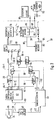
- a control circuit 28 supplies the transmitters of the first group via a transmission line 30-1 and the transmitters of the second group via a transmission line 30-2. Corresponding transmission lines, which are not shown in more detail, supply the transmitters of group three or group four.
- the first receiver 20.1 is connected to the control circuit 28 via a receiver line 32-1, while the second receiver 20.2 is connected to the control circuit 28 via a second line 32-2.
- the third receiver 20.3 and the fourth receiver 20.4 are with the control circuit 28 connected.
- a signal generating device 36 which generates a start signal 38, is switched on via a main switch 34.
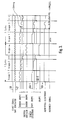
- the start signal 38 is fed to a clock generator 40, which generates a rectangular pulse train in the form of a clock signal 42.
- the clock signal 42 coming from the clock generator 40 is fed to a transmitter control 46 via a clock line 44.
- the transmitter control 46 transmits transmission signals S1 to a first transmitter group 50 via a first transmission line 48.
- the transmitter control 46 applies transmission signals S2 to a second transmitter group 54 via a second line 52. From the transmission control lead further transmission lines, which lead corresponding transmission signals to other transmitter groups n depending on the number of connected transmitter groups. In the embodiment according to FIG. 1, this would be four transmitter groups, each with 4 transmitter lines.
- Transmit signals 56 are transmitted from the first transmitter group 50 to the first receiver 20.1 of the first group.
- transmission signals 58 are transmitted from the second transmitter group 54 to the second receiver 20.2 of the second group.
- a comparison signal line leads comparison signals from the transmitter control to a transmitter-receiver group distributor 62, from where the comparison signals 64-1 to 64-m are passed on to the respective receivers of the respective groups.
- the comparison signal 64 is compared with the received transmitter signals 56 or 58, etc., in relation to one another, which can be done, for example, by a logical AND operation.
- the receiver output signals 66-1 or 66-2 to 66-m are applied to a receiver collector circuit 68, from where they are fed to a common receiver signal evaluation circuit 70 via a collector line 72.
- the evaluation signal 74 is fed via an evaluation signal line 76 to a self-monitoring circuit 78.
- This self-monitoring circuit 78 is preferably designed as a fail-safe circuit. From it, signals are routed via a fault reporting line 80 into a fault reporting circuit 82, which then supplies the detection signals 84.
- the self-monitoring circuit 78 has a relay 86, which connects the folding gate control 90 to the folding gate drive 92 via its relay contact 88. The actuation of the relay contact 88 can also be used as a detection signal 84 ', whereby an alarm system or other monitoring devices can also be actuated instead of controlling a high-speed door.
Landscapes
- General Physics & Mathematics (AREA)
- General Engineering & Computer Science (AREA)
- Engineering & Computer Science (AREA)
- Physics & Mathematics (AREA)
- General Life Sciences & Earth Sciences (AREA)
- Life Sciences & Earth Sciences (AREA)
- Mechanical Engineering (AREA)
- Geophysics (AREA)
- Geophysics And Detection Of Objects (AREA)
- Burglar Alarm Systems (AREA)
- Radar Systems Or Details Thereof (AREA)
- Power-Operated Mechanisms For Wings (AREA)
- Selective Calling Equipment (AREA)
Claims (11)
- Dispositif de reconnaissance d'une atténuation d'un signal émis séquentiellement par plus de deux émetteurs (S1.1-S1.n, S2.1-S2.n, ..., Sm.1-Sm.n) dans un espace situé entre les émetteurs et un récepteur (20.1, 20.2, ..., 20.m), comprenant un circuit de commande (28) auquel tous les émetteurs (S1.1-S1.n, S2.1-S2.n, ..., Sm.1-Sm.n) sont reliés et le récepteur (20.1, 20.2, ..., 20.m), et dans lequel le circuit de commande (28) envoie aux émetteurs (S1.1-S1.n, S2.1-S2.n, ..., Sm.1-Sm.n) des signaux qui sont transformés par les émetteurs (S1.1-S1.n, S2.1-S2.n, ..., Sm.1-Sm.n) en signaux d'émission, qui sont susceptibles d'être reçus par le récepteur (20.1, 20.2, ..., 20.m) et qui sont transmis à nouveau au circuit de commande (28), dans lequel le circuit de commande fournit cycliquement et séquentiellement les signaux aux émetteurs (S1.1-S1.n, S2.1-S2.n, ..., Sm.1-Sm.n) et dans lequel les émetteurs (S1.1-S1.n, S2.1-S2.n, ..., Sm.1-Sm.n) sont chacun associés au récepteur et constituent avec le récepteur (20.1, 20.2, ..., 20.m) un groupe émetteurs récepteur, caractérisé en ce que:- chaque partie de l'aire ou de l'espace à surveiller est recouverte uniquement par un groupe émetteurs-récepteur associé, chaque émetteur (S1.1-S1.n, S2.1-S2.n, ..., Sm.1-Sm.n) d'un groupe d'émetteurs ne fournissant son signal qu'à son récepteur associé (20.1, 20.2, ..., 20.m);- au moins deux groupes émetteurs-récepteur sont prévus de telle sorte que les récepteurs (20.1, 20.2, ..., 20.m) se font face en diagonale;- les émetteurs (S1.1-S1.n, S2.1-S2.n, ..., Sm.1-Sm.n) forment avec les récepteurs (20.1, 20.2. ..., 20.m) chacun une surface constituant un triangle rectangle; et en ce que- les signaux arrivant des récepteurs (20.1, 20.2, ..., 20.m) sont fournis à un circuit d'évaluation de fréquence et/ou d'amplitude dans le circuit de commande (28) qui donne un signal d'évaluation (74).
- Dispositif selon la revendication 1, caractérisé en ce que le circuit de commande (28) produit des signaux d'horloge (42) en forme d'impulsions, produits par un générateur d'horloge (40).
- Dispositif selon une des revendications 1 ou 2, caractérisé en ce qu'il comprend un circuit comparateur qui compare en fréquence et/ou en amplitude les signaux provenant du circuit d'évaluation et ceux délivrés aux émetteurs (S1.1-S1.n, S2.1-S2.n, ..., Sm.1-Sm.n), et qui, en cas d'écart, fournit un signal de commutation qui est transformable en signal d'évaluation (74).
- Dispositif selon l'une des revendications 1 à 3, caractérisé en ce qu'il comprend un circuit à sécurité intégrée, grâce auquel les fonctions de toutes les unités d'émetteurs, de récepteurs et de circuits sont surveillées.
- Dispositif selon l'une des revendications 1 à 4, caractérisé en ce que les émetteurs (S1.1-S1.n, S2.1-S2.n, ..., Sm.1-Sm.n) sont disposés suivant une ligne.
- Dispositif selon l'une des revendications 1 à 5, caractérisé en ce que l'espace intermédiaire (10) est géométriquement entièrement recouvert par les plans émetteurs/récepteur des différents groupes d'émetteurs (S1.1-S1.n, S2.1-S2.n, ..., Sm.1-Sm.n) et de récepteurs (20.1, 20.2, ..., 20.m).
- Dispositif selon l'une des revendications 1 à 6, caractérisé en ce que les émetteurs (S1.1-S1.n, S2.1-S2.n, ..., Sm.1-Sm.n) comprennent des diodes électro-luminescentes, et le récepteur (20.1, 20.2, ..., 20.m) comprend un élément capteur de la lumière.
- Dispositif selon la revendication 7, caractérisé en ce que les diodes électro-luminescentes sont constituées de diodes infrarouges et l'élément capteur de la lumière est constitué d'un récepteur infrarouge.
- Dispositif selon la revendication 7 ou 8, caractérisé en ce que les diodes électro-luminescentes présentent un angle de dispersion d'au moins 20°.
- Dispositif selon l'une des revendications 1 à 9, caractérisé en ce que plusieurs groupes d'émetteurs (S1.1-S1.n, S2.1-S2.n, ..., Sm.1-Sm.n) et de récepteurs (20.1, 20.2, ..., 20.m) présentent un circuit de commande (28) commun.
- Dispositif selon la revendication 10, caractérisé en ce que les émetteurs (S1.1-S1.n, S2.1-S2.n, ..., Sm.1-Sm.n) de chaque groupe et/ou de tous les groupes sont commandés par une commande d'émission (46).
Priority Applications (1)
| Application Number | Priority Date | Filing Date | Title |
|---|---|---|---|
| AT87101640T ATE72491T1 (de) | 1986-02-07 | 1987-02-06 | Vorrichtung zur erkennung einer abschattung eines von mindestens einem sender ausgesandten signals in einem zwischen dem sender und empfaenger befindlichen zwischenraum. |
Applications Claiming Priority (2)
| Application Number | Priority Date | Filing Date | Title |
|---|---|---|---|
| DE3603927 | 1986-02-07 | ||
| DE19863603927 DE3603927A1 (de) | 1986-02-07 | 1986-02-07 | Vorrichtung zur erkennung einer abschattung eines von mindestens einem sender ausgesandten signales in einem zwischen dem sender und empfaenger befindlichen zwischenraum |
Publications (2)
| Publication Number | Publication Date |
|---|---|
| EP0236755A1 EP0236755A1 (fr) | 1987-09-16 |
| EP0236755B1 true EP0236755B1 (fr) | 1992-02-05 |
Family
ID=6293665
Family Applications (1)
| Application Number | Title | Priority Date | Filing Date |
|---|---|---|---|
| EP87101640A Expired - Lifetime EP0236755B1 (fr) | 1986-02-07 | 1987-02-06 | Dispositif de détection d'une interruption dans un espace situé entre l'émetteur et le récepteur d'un signal lumineux émis d'au moins un émetteur |
Country Status (4)
| Country | Link |
|---|---|
| EP (1) | EP0236755B1 (fr) |
| AT (1) | ATE72491T1 (fr) |
| DE (2) | DE3603927A1 (fr) |
| YU (1) | YU16587A (fr) |
Cited By (2)
| Publication number | Priority date | Publication date | Assignee | Title |
|---|---|---|---|---|
| US7034682B2 (en) | 2003-06-20 | 2006-04-25 | Rite-Hite Holding Corporation | Door with a safety antenna |
| US7045764B2 (en) | 2002-10-17 | 2006-05-16 | Rite-Hite Holding Corporation | Passive detection system for detecting a body near a door |
Families Citing this family (8)
| Publication number | Priority date | Publication date | Assignee | Title |
|---|---|---|---|---|
| DE3728354A1 (de) * | 1987-08-25 | 1989-03-09 | Azovskoe Sp K B Kuznechno Pres | Lichtschrankenanordnung |
| FR2626096B1 (fr) * | 1988-01-19 | 1992-02-14 | Breuil Sa | Appareil de comptage d'objets defilant |
| GB2227309A (en) * | 1989-01-18 | 1990-07-25 | Formula Systems Ltd | Detection system |
| CH681756A5 (fr) * | 1990-11-12 | 1993-05-14 | Beat Decoi | |
| WO1992019990A1 (fr) * | 1991-05-07 | 1992-11-12 | Belgian Electronic Research, B.E.R., S.A. | Dispositif de detection autoreglable et autoadaptatif |
| DE4326099A1 (de) * | 1993-08-04 | 1995-02-09 | Hella Kg Hueck & Co | Lichtschrankensystem |
| DE4338978C2 (de) * | 1993-11-15 | 1998-05-07 | Sick Ag | Verfahren zur Feststellung defekter Lichtsender und/oder Lichtempfänger eines Lichtgitters und Lichtgitter |
| IT1284601B1 (it) * | 1996-09-27 | 1998-05-21 | Ottorino Barbuti | Barriera di sicurezza a raggi infrarossi |
Family Cites Families (7)
| Publication number | Priority date | Publication date | Assignee | Title |
|---|---|---|---|---|
| GB1404913A (en) * | 1973-01-09 | 1975-09-03 | Byrne R C | Protable security system |
| US3805061A (en) * | 1973-04-23 | 1974-04-16 | Tyco Laboratories Inc | Object detecting apparatus |
| CA1036686A (fr) * | 1973-10-29 | 1978-08-15 | George L. Schofield (Jr.) | Dispositif de detection autoverificateur |
| DE2540741A1 (de) * | 1975-09-12 | 1977-03-17 | Elektronik Apparatebau Gmbh | Ir-sicherungsanlage |
| AU509436B2 (en) * | 1976-05-05 | 1980-05-15 | 3M Australia Pty Limited | Optoelectronic detection apparatus |
| DE2648631C2 (de) * | 1976-10-27 | 1986-07-10 | Licentia Patent-Verwaltungs-Gmbh, 6000 Frankfurt | Lichtelektrische Schranke mit Paaren von lichtelektrischen Sendern und Empfängern |
| DE2851444C2 (de) * | 1978-11-28 | 1983-05-26 | Erwin Sick Gmbh Optik-Elektronik, 7808 Waldkirch | Lichtgitter |
-
1986
- 1986-02-07 DE DE19863603927 patent/DE3603927A1/de not_active Withdrawn
-
1987
- 1987-02-05 YU YU00165/87A patent/YU16587A/xx unknown
- 1987-02-06 DE DE8787101640T patent/DE3776580D1/de not_active Expired - Fee Related
- 1987-02-06 EP EP87101640A patent/EP0236755B1/fr not_active Expired - Lifetime
- 1987-02-06 AT AT87101640T patent/ATE72491T1/de active
Cited By (3)
| Publication number | Priority date | Publication date | Assignee | Title |
|---|---|---|---|---|
| US7045764B2 (en) | 2002-10-17 | 2006-05-16 | Rite-Hite Holding Corporation | Passive detection system for detecting a body near a door |
| US7034682B2 (en) | 2003-06-20 | 2006-04-25 | Rite-Hite Holding Corporation | Door with a safety antenna |
| US7151450B2 (en) | 2003-06-20 | 2006-12-19 | Rite-Hite Holding Corporation | Door with a safety antenna |
Also Published As
| Publication number | Publication date |
|---|---|
| YU16587A (en) | 1989-10-31 |
| ATE72491T1 (de) | 1992-02-15 |
| DE3603927A1 (de) | 1987-08-13 |
| EP0236755A1 (fr) | 1987-09-16 |
| DE3776580D1 (de) | 1992-03-19 |
Similar Documents
| Publication | Publication Date | Title |
|---|---|---|
| EP0232866B1 (fr) | Dispositif de commande de l'ouverture et/ou fermeture de portes à mouvement rapide | |
| EP1723446B1 (fr) | Dispositif de controle d'acces | |
| DE69519066T2 (de) | Aufzugsvorrichtung zur Verhinderung des vorzeitigen Verschlusses von Schiebetüren | |
| DE3689612T2 (de) | Annäherungsdetektor. | |
| EP2453252B1 (fr) | Capteur 3D à économie d'énergie | |
| DE3514982A1 (de) | Vorrichtung mit photosensoren zum erfassen von objekten in einem begrenzten erfassungsbereich | |
| DE102008023294A1 (de) | Sicherungssystem zur Absicherung eines sich bewegenden, geführten Bewegungselements gegen ungewollte Kollisionen | |
| DE2821681A1 (de) | Lichtschrankensystem | |
| DE3908273C1 (en) | Self-test device for a scanning light probe | |
| EP0818412A1 (fr) | Barrière optique pour réouvrir des portes d'ascenseur | |
| EP0236755A1 (fr) | Dispositif de détection d'une interruption dans un espace situé entre l'émetteur et le récepteur d'un signal lumineux émis d'au moins un émetteur | |
| EP1336122B1 (fr) | Ensemble capteur pour la surveillance d'une zone spatiale | |
| DE3344576C1 (de) | Sensoranordnung zur Überwachung des Schwenkbereiches von Türflügeln | |
| DE2539438A1 (de) | Strahlenschranke | |
| DE10001017B4 (de) | Optoelektronischer Sensor, insbesondere Reflexlichttaster | |
| EP2453426A1 (fr) | Capteur de surveillance doté d'un autotest | |
| DE102005011116A1 (de) | Vorrichtung zur Ansteuerung und/oder Überwachung eines Flügels | |
| DE102020119925A1 (de) | Automatische Drehflügeltür und Sensor | |
| EP0852313B1 (fr) | Dispositif pour la commande et/ou pour sécuriser les panneaux de portes motorisés, fenêtres ou analogues | |
| DE2528125A1 (de) | Lichtschranken-anordnung | |
| EP0747865A2 (fr) | Dispositif de détermination du sens de déplacement d'une personne | |
| DE8603304U1 (de) | Schnellauftorvorrichtung | |
| DE102013018800A1 (de) | Verfahren und Vorrichtung zum optischen Bestimmen von Abständen zu Objekten in einem Überwachungsbereich, insbesondere in einem Überwachungsbereich von automatischen Türen | |
| DE19537051C1 (de) | Optoelektronische Sensoranordnung | |
| AT396188B (de) | Verfahren zum ueberwachen des raumes zwischen kraftbewegten einrichtungen |
Legal Events
| Date | Code | Title | Description |
|---|---|---|---|
| PUAI | Public reference made under article 153(3) epc to a published international application that has entered the european phase |
Free format text: ORIGINAL CODE: 0009012 |
|
| AK | Designated contracting states |
Kind code of ref document: A1 Designated state(s): AT BE CH DE FR GB IT LI NL SE |
|
| 17P | Request for examination filed |
Effective date: 19880316 |
|
| 17Q | First examination report despatched |
Effective date: 19900622 |
|
| GRAA | (expected) grant |
Free format text: ORIGINAL CODE: 0009210 |
|
| AK | Designated contracting states |
Kind code of ref document: B1 Designated state(s): AT BE CH DE FR GB IT LI NL SE |
|
| REF | Corresponds to: |
Ref document number: 72491 Country of ref document: AT Date of ref document: 19920215 Kind code of ref document: T |
|
| ET | Fr: translation filed | ||
| GBT | Gb: translation of ep patent filed (gb section 77(6)(a)/1977) | ||
| REF | Corresponds to: |
Ref document number: 3776580 Country of ref document: DE Date of ref document: 19920319 |
|
| ITF | It: translation for a ep patent filed | ||
| PLBE | No opposition filed within time limit |
Free format text: ORIGINAL CODE: 0009261 |
|
| STAA | Information on the status of an ep patent application or granted ep patent |
Free format text: STATUS: NO OPPOSITION FILED WITHIN TIME LIMIT |
|
| PGFP | Annual fee paid to national office [announced via postgrant information from national office to epo] |
Ref country code: FR Payment date: 19930121 Year of fee payment: 7 |
|
| PGFP | Annual fee paid to national office [announced via postgrant information from national office to epo] |
Ref country code: BE Payment date: 19930122 Year of fee payment: 7 |
|
| PGFP | Annual fee paid to national office [announced via postgrant information from national office to epo] |
Ref country code: GB Payment date: 19930126 Year of fee payment: 7 |
|
| 26N | No opposition filed | ||
| PGFP | Annual fee paid to national office [announced via postgrant information from national office to epo] |
Ref country code: AT Payment date: 19930212 Year of fee payment: 7 |
|
| PGFP | Annual fee paid to national office [announced via postgrant information from national office to epo] |
Ref country code: CH Payment date: 19930222 Year of fee payment: 7 |
|
| PGFP | Annual fee paid to national office [announced via postgrant information from national office to epo] |
Ref country code: SE Payment date: 19930224 Year of fee payment: 7 |
|
| PGFP | Annual fee paid to national office [announced via postgrant information from national office to epo] |
Ref country code: NL Payment date: 19930228 Year of fee payment: 7 |
|
| PGFP | Annual fee paid to national office [announced via postgrant information from national office to epo] |
Ref country code: DE Payment date: 19930325 Year of fee payment: 7 |
|
| PG25 | Lapsed in a contracting state [announced via postgrant information from national office to epo] |
Ref country code: GB Effective date: 19940206 Ref country code: AT Effective date: 19940206 |
|
| PG25 | Lapsed in a contracting state [announced via postgrant information from national office to epo] |
Ref country code: SE Effective date: 19940207 |
|
| PG25 | Lapsed in a contracting state [announced via postgrant information from national office to epo] |
Ref country code: LI Effective date: 19940228 Ref country code: CH Effective date: 19940228 Ref country code: BE Effective date: 19940228 |
|
| BERE | Be: lapsed |
Owner name: EFAFLEX TRANSPORT- UND LAGERTECHNIK G.M.B.H. Effective date: 19940228 |
|
| PG25 | Lapsed in a contracting state [announced via postgrant information from national office to epo] |
Ref country code: NL Effective date: 19940901 |
|
| GBPC | Gb: european patent ceased through non-payment of renewal fee |
Effective date: 19940206 |
|
| NLV4 | Nl: lapsed or anulled due to non-payment of the annual fee | ||
| PG25 | Lapsed in a contracting state [announced via postgrant information from national office to epo] |
Ref country code: FR Effective date: 19941031 |
|
| REG | Reference to a national code |
Ref country code: CH Ref legal event code: PL |
|
| PG25 | Lapsed in a contracting state [announced via postgrant information from national office to epo] |
Ref country code: DE Effective date: 19941101 |
|
| REG | Reference to a national code |
Ref country code: FR Ref legal event code: ST |
|
| EUG | Se: european patent has lapsed |
Ref document number: 87101640.8 Effective date: 19940910 |
|
| PG25 | Lapsed in a contracting state [announced via postgrant information from national office to epo] |
Ref country code: IT Free format text: LAPSE BECAUSE OF NON-PAYMENT OF DUE FEES;WARNING: LAPSES OF ITALIAN PATENTS WITH EFFECTIVE DATE BEFORE 2007 MAY HAVE OCCURRED AT ANY TIME BEFORE 2007. THE CORRECT EFFECTIVE DATE MAY BE DIFFERENT FROM THE ONE RECORDED. Effective date: 20050206 |