EP0237107A1 - Optisches Relais zur Erzeugung eines projizierten Bildes, das verbessert lesbare Buchstaben enthält - Google Patents
Optisches Relais zur Erzeugung eines projizierten Bildes, das verbessert lesbare Buchstaben enthält Download PDFInfo
- Publication number
- EP0237107A1 EP0237107A1 EP87200319A EP87200319A EP0237107A1 EP 0237107 A1 EP0237107 A1 EP 0237107A1 EP 87200319 A EP87200319 A EP 87200319A EP 87200319 A EP87200319 A EP 87200319A EP 0237107 A1 EP0237107 A1 EP 0237107A1
- Authority
- EP
- European Patent Office
- Prior art keywords
- target
- optical relay
- image
- light
- overmodulation
- Prior art date
- Legal status (The legal status is an assumption and is not a legal conclusion. Google has not performed a legal analysis and makes no representation as to the accuracy of the status listed.)
- Withdrawn
Links
- 230000003287 optical effect Effects 0.000 title claims abstract description 29
- 230000005684 electric field Effects 0.000 claims abstract description 8
- 230000000007 visual effect Effects 0.000 claims abstract description 8
- 230000001419 dependent effect Effects 0.000 claims abstract description 5
- 239000012777 electrically insulating material Substances 0.000 claims abstract description 3
- 238000005286 illumination Methods 0.000 claims description 10
- 230000009471 action Effects 0.000 claims description 3
- 239000000463 material Substances 0.000 claims description 3
- 238000010408 sweeping Methods 0.000 abstract 1
- 239000013078 crystal Substances 0.000 description 20
- 238000010894 electron beam technology Methods 0.000 description 8
- 235000019796 monopotassium phosphate Nutrition 0.000 description 5
- 230000010287 polarization Effects 0.000 description 4
- 230000005697 Pockels effect Effects 0.000 description 3
- 230000007423 decrease Effects 0.000 description 2
- 210000000056 organ Anatomy 0.000 description 2
- 230000006641 stabilisation Effects 0.000 description 2
- 238000011105 stabilization Methods 0.000 description 2
- 230000009466 transformation Effects 0.000 description 2
- YZCKVEUIGOORGS-OUBTZVSYSA-N Deuterium Chemical compound [2H] YZCKVEUIGOORGS-OUBTZVSYSA-N 0.000 description 1
- UFHFLCQGNIYNRP-VVKOMZTBSA-N Dideuterium Chemical compound [2H][2H] UFHFLCQGNIYNRP-VVKOMZTBSA-N 0.000 description 1
- UFHFLCQGNIYNRP-UHFFFAOYSA-N Hydrogen Chemical compound [H][H] UFHFLCQGNIYNRP-UHFFFAOYSA-N 0.000 description 1
- 239000007836 KH2PO4 Substances 0.000 description 1
- 229910019142 PO4 Inorganic materials 0.000 description 1
- ZLMJMSJWJFRBEC-UHFFFAOYSA-N Potassium Chemical compound [K] ZLMJMSJWJFRBEC-UHFFFAOYSA-N 0.000 description 1
- 238000010521 absorption reaction Methods 0.000 description 1
- 239000002253 acid Substances 0.000 description 1
- 230000004075 alteration Effects 0.000 description 1
- WUKWITHWXAAZEY-UHFFFAOYSA-L calcium difluoride Chemical compound [F-].[F-].[Ca+2] WUKWITHWXAAZEY-UHFFFAOYSA-L 0.000 description 1
- 230000008859 change Effects 0.000 description 1
- 230000008602 contraction Effects 0.000 description 1
- 230000006866 deterioration Effects 0.000 description 1
- 229910052805 deuterium Inorganic materials 0.000 description 1
- 238000010586 diagram Methods 0.000 description 1
- 230000000694 effects Effects 0.000 description 1
- 230000002349 favourable effect Effects 0.000 description 1
- 239000010436 fluorite Substances 0.000 description 1
- PCHJSUWPFVWCPO-UHFFFAOYSA-N gold Chemical compound [Au] PCHJSUWPFVWCPO-UHFFFAOYSA-N 0.000 description 1
- 239000010931 gold Substances 0.000 description 1
- 229910052737 gold Inorganic materials 0.000 description 1
- 229910052739 hydrogen Inorganic materials 0.000 description 1
- 239000001257 hydrogen Substances 0.000 description 1
- 238000005259 measurement Methods 0.000 description 1
- 229910000402 monopotassium phosphate Inorganic materials 0.000 description 1
- 239000000615 nonconductor Substances 0.000 description 1
- 230000005693 optoelectronics Effects 0.000 description 1
- 230000003071 parasitic effect Effects 0.000 description 1
- 239000010452 phosphate Substances 0.000 description 1
- NBIIXXVUZAFLBC-UHFFFAOYSA-K phosphate Chemical compound [O-]P([O-])([O-])=O NBIIXXVUZAFLBC-UHFFFAOYSA-K 0.000 description 1
- 230000000704 physical effect Effects 0.000 description 1
- 229910052700 potassium Inorganic materials 0.000 description 1
- 239000011591 potassium Substances 0.000 description 1
- GNSKLFRGEWLPPA-UHFFFAOYSA-M potassium dihydrogen phosphate Chemical compound [K+].OP(O)([O-])=O GNSKLFRGEWLPPA-UHFFFAOYSA-M 0.000 description 1
- 230000001902 propagating effect Effects 0.000 description 1
- 108090000623 proteins and genes Proteins 0.000 description 1
- 230000005855 radiation Effects 0.000 description 1
- 150000003839 salts Chemical class 0.000 description 1
- 230000002269 spontaneous effect Effects 0.000 description 1
Images

Classifications
-
- H—ELECTRICITY
- H04—ELECTRIC COMMUNICATION TECHNIQUE
- H04N—PICTORIAL COMMUNICATION, e.g. TELEVISION
- H04N5/00—Details of television systems
- H04N5/74—Projection arrangements for image reproduction, e.g. using eidophor
- H04N5/7416—Projection arrangements for image reproduction, e.g. using eidophor involving the use of a spatial light modulator, e.g. a light valve, controlled by a video signal
- H04N5/7441—Projection arrangements for image reproduction, e.g. using eidophor involving the use of a spatial light modulator, e.g. a light valve, controlled by a video signal the modulator being an array of liquid crystal cells
Definitions
- the invention relates to an optical relay comprising a target of an electrically insulating material and allowing light to pass in a manner dependent on the electric field parallel to the direction of propagation of this light, means for scanning a first face of this target. by an electronic beam controlled by a wehnelt, an anode capable of collecting the secondary electrons emitted under the action of this beam, an optically transparent and electrically conductive blade placed against the second face of the target, this blade receiving the electrical signal from visual information from an amplifier which delivers a video signal modulating the target potential, this being made of a material becoming ferroelectric below a certain temperature, called Curie temperature, in the vicinity of which operates the optical relay.
- the scope of the invention relates to the transformation of an electric signal with time variation, representing visual information, into a visible image. We know that this is one of the roles of a television receiver.
- the beam power, and therefore the brightness of the image cannot be increased as much as it should be for projection on a large screen, for example.
- KDP potassium diacid phosphate crystal
- the beam electrons When the beam electrons reach the surface of the target, they cause, if their energy is within suitable limits and as long as the anode potential is sufficiently high, the emission of secondary electrons in greater number than that of incident electrons. This results in an increase in the electrical potential of the point reached, so that the potential difference between the anode and this point decreases. If the electrons of the beam reach this point in sufficient number, this potential difference becomes negative and reaches a value such (-3V for example), that each incident electron no longer causes the emission of more than one secondary electron. The potential of this point is thus fixed at a limit value relative to that of the anode. It suffices for this that, taking into account the scanning speed, the intensity of the beam is sufficient.
- this charge is proportional to VO-VA, VA representing the value of the visual information signal at the time of its passage.
- the target whose birefringence depends on the electric field, consists of a single crystal of KDP, of which approximately 95% of the hydrogen has the form of heavy hydrogen (deuterium).
- the Pockels effect is proportional, for a given crystal thickness, to the charges which appear on the faces of the crystal and therefore, for a given control voltage, to the dielectric constant thereof.
- a target made up of a crystal becoming ferroelectric below a certain temperature called Curie temperature we operate advantageously near this temperature, because the dielectric constant then reaches very high values and the optical relay can operate using easy-to-use control voltages (the Pockels effect being proportional to the product ⁇ V).
- the most common crystals which exhibit this phenomenon are acid salts, in particular of the KDP type which belongs to the class of quadratic crystals and has an optical axis parallel to the crystallographic axis c.
- Its Curie temperature is around -53 ° C. Above the Curie temperature, the DKDP is a quadratic crystal class of symmetry 2 m and it has a paraelectric behavior. Below the Curie temperature, the DKDP becomes orthorhombic, class of symmetry mm2, and it manifests a ferroelectric behavior: locally there is spontaneous polarization and appearance of ferroelectric domains.
- the crystal is anisotropic, but in the vicinity of the Curie point the anisotropy becomes extremely important.
- the change of state was accompanied gene of abrupt variations of the physical properties according to the axes of the crystal: - piezoelectric coefficients - electro-optical coefficients - dielectric constants ⁇ x and ⁇ z .
- the dielectric constant ⁇ ' z goes from a value of around 60 at ambient temperature to a value of 30,000 at Curie temperature.
- the target appears the thinner the smaller the ratio ⁇ x / ⁇ z , where ⁇ z is the value of ⁇ z when the crystal is mechanically blocked.
- the monocrystalline blade of DKDP with a thickness E close to 250 microns, is firmly glued to a rigid support: a fluorite blade 5 mm thick.
- the target of the optical relay is therefore usually cooled to -51 ° C, that is to say to a temperature slightly above the Curie point.
- ⁇ x ⁇ z 1/9 and the apparent thickness of the crystal is approximately 80 microns, which gives the optical relay good image resolution.
- this ratio ⁇ x / ⁇ z is even much lower, which greatly improves the image resolution.
- the object of the invention is therefore to increase readability mainly for data such as lines and / or alphanumeric characters.
- the invention as defined in the preamble is remarkable in that the optical relay comprises another amplifier which applies, on the wehnelt of the optical relay, a slight overmodulation resulting from the video signal, and in connection with the average level d global illumination of the image produced by the modulation of the target potential alone, the polarity and the amplitude of this over-modulation can be adjusted so as to produce, for light or dark characters respectively, a proportional increase in their level of illumination or of their level of darkness.
- an amplifier which applies at low dose to the wehnelt of the optical relay an overmodulation resulting from the same video signal as that which is applied to the target.
- the stabilized beam current which corresponds to it is 10 microamps.
- an over-modulation of +6 volts is superimposed on the wehnelt, the current then passing to a value of 10.8 microamps. This variation is small enough not to disrupt the focusing of the beam.
- This over-modulation is therefore dependent on the content of the image. If this content is very little modified on the light plane, for example with a regular display of alphanumeric characters, the adjustment of the over-modulation can be operated by the user when the need appears. But when this content is very changeable and causes large variations in image illumination, this adjustment of the over-modulation can be carried out automatically using an image integrator, which determines the average level of overall illumination. of the image. This integrator controls the polarity and the over-modulation rate to be applied to the wehnelt via the amplifier.
- Figure 1 are schematically represented, the essential organs of an optical relay according to the invention, and those which cooperate with this relay to obtain a visible image, projected on a screen 2 by a projection lens 4.
- the light is supplied by a lamp 6, shown as being incandescent, but which could obviously be of any other type.
- This light passes through a collimating lens 8, then a tank 10 whose role is to stop the infrared heat radiation.
- the optical relay is essentially constituted by a target 12, formed by a parallelepipedal single crystal of KDP whose optical axis (c) is perpendicular to the large faces, and placed between the two crossed polarizers 14 and 16 whose polarization planes are parallel to the other two crystallographic axes (a and b) of the single crystal.
- a heat exchanger 18 is in contact with the target 12 and maintains it near its Curie temperature.
- the left face of this target receives an electron beam, shown in dotted lines and coming from an electron gun 20.
- This beam periodically scans the entire useful surface of the target 12 under the action of deflection members 22 controlled by the scanning signals from a receiver 24 which develops them from the synchronization signals which are supplied to it at its input 26 with the visual information signal proper.
- a block 28 provides some of the organs already mentioned with the DC voltages they need, as well as an anode 30. This it is only for the clarity of the drawing that it is represented in the form of a plate parallel to the light beam, because it is obvious that this arrangement, very favorable to the passage of light is hardly so in the collection secondary electrons emitted by all the points on the surface of the target 12 reached by the electron beam. This is why, in practice, the anode is arranged parallel to the surface of the target 12 and very close to it.
- An electrically conductive and optically transparent blade 38 is disposed behind the target 12. It is to this blade that the receiver 24 applies the visual information signal.
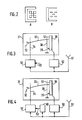
- FIG. 2 represents in A a character to be reproduced formed by horizontal and vertical parts representing the letter C surrounding five squares in contact by vertices.
- an optical relay according to the prior art, there are inaccuracies of restitutions of such a character.
- the horizontal parts are thinned and the squares thus become non-contiguous.
- Drawing B incorrectly reproduces these distortions because in addition there is a loss of definition of the character which can make the character illegible.
- FIG. 3 schematically represents an optical relay 31, as shown in FIG. 1. It comprises a cathode 32 emitting an electron beam 33 which passes through a wehnelt 34 and arrives at the target 12.
- the blade 38 which receives the video signal from the amplifier 50, modulates the charge of the front face 35 of the target which is effected by the electron beam 33 at initially constant current.
- the anode-gate 30 connected to ground, controls the potential of this front face 35 so that this initial modulation is carried out in potential stabilization.
- the video signal from a video source symbolically represented in the example by an antenna 51 is introduced into the amplifier 50.
- the invention uses a second amplifier 52, also connected to the same video source, which applies to the wehnelt 34 low over-modulation. This slightly modulates the initially constant beam current and thus modifies the potential of the front face 35 of the target.
- the rate and the polarity of the overmodulation must be adjusted.
- the user using a command 53, can therefore make this adjustment with respect to the average overall level of illumination of the image.
- the invention uses an image integrator 40 connected to the video source which integrates the light content of the image on one or more frames or in a particular area of the image, and performs automatically adjustment of the level and polarity of the overmodulation with respect to this average level of overall illumination of the image.
Landscapes
- Chemical & Material Sciences (AREA)
- Crystallography & Structural Chemistry (AREA)
- Engineering & Computer Science (AREA)
- Multimedia (AREA)
- Signal Processing (AREA)
- Transforming Electric Information Into Light Information (AREA)
- Liquid Crystal Display Device Control (AREA)
Applications Claiming Priority (2)
| Application Number | Priority Date | Filing Date | Title |
|---|---|---|---|
| FR8602992A FR2595495B1 (fr) | 1986-03-04 | 1986-03-04 | Relais optique fournissant une image projetee qui presente des caracteres ayant une lisibilite accrue |
| FR8602992 | 1986-03-04 |
Publications (1)
| Publication Number | Publication Date |
|---|---|
| EP0237107A1 true EP0237107A1 (de) | 1987-09-16 |
Family
ID=9332727
Family Applications (1)
| Application Number | Title | Priority Date | Filing Date |
|---|---|---|---|
| EP87200319A Withdrawn EP0237107A1 (de) | 1986-03-04 | 1987-02-25 | Optisches Relais zur Erzeugung eines projizierten Bildes, das verbessert lesbare Buchstaben enthält |
Country Status (5)
| Country | Link |
|---|---|
| US (1) | US4866529A (de) |
| EP (1) | EP0237107A1 (de) |
| JP (1) | JPS62234119A (de) |
| DK (1) | DK103587A (de) |
| FR (1) | FR2595495B1 (de) |
Families Citing this family (2)
| Publication number | Priority date | Publication date | Assignee | Title |
|---|---|---|---|---|
| US4864538A (en) * | 1988-05-05 | 1989-09-05 | Tektronix, Inc. | Method and apparatus for addressing optical data storage locations |
| JPH03282515A (ja) * | 1990-03-30 | 1991-12-12 | Fujitsu General Ltd | 表示装置 |
Citations (1)
| Publication number | Priority date | Publication date | Assignee | Title |
|---|---|---|---|---|
| US3520589A (en) * | 1966-01-26 | 1970-07-14 | Philips Corp | Optical relay for television purposes |
Family Cites Families (7)
| Publication number | Priority date | Publication date | Assignee | Title |
|---|---|---|---|---|
| GB441505A (en) * | 1934-08-28 | 1936-01-21 | Ernest Edward Wright | Improvements in or relating to television, telecinematographic and like systems |
| US2983824A (en) * | 1955-05-06 | 1961-05-09 | Ibm | Electro-optical point shutter |
| FR1473212A (fr) * | 1966-01-26 | 1967-03-17 | Electronique & Physique | Relais optique applicable à la télévision |
| US3637931A (en) * | 1968-12-20 | 1972-01-25 | Philips Corp | Optic relay for use in television |
| DE2103542A1 (de) * | 1970-01-26 | 1971-08-12 | Thomson Csf | Kraftmeßvorrichtung |
| FR2386222A1 (fr) * | 1977-03-30 | 1978-10-27 | Videon Sa | Systeme de television en relief par holographie |
| US4692758A (en) * | 1984-04-02 | 1987-09-08 | International Business Machines Corporation | Legibility enhancement for alphanumeric displays |
-
1986
- 1986-03-04 FR FR8602992A patent/FR2595495B1/fr not_active Expired
-
1987
- 1987-02-25 EP EP87200319A patent/EP0237107A1/de not_active Withdrawn
- 1987-02-27 DK DK103587A patent/DK103587A/da not_active Application Discontinuation
- 1987-03-02 JP JP62045380A patent/JPS62234119A/ja active Pending
- 1987-03-02 US US07/020,924 patent/US4866529A/en not_active Expired - Fee Related
Patent Citations (1)
| Publication number | Priority date | Publication date | Assignee | Title |
|---|---|---|---|---|
| US3520589A (en) * | 1966-01-26 | 1970-07-14 | Philips Corp | Optical relay for television purposes |
Non-Patent Citations (1)
| Title |
|---|
| 1985 SID INTERNATIONAL SYMPOSIUM DIGEST OF TECHNICAL PAPERS, Society for SID Information Display, 1ère édition, mai 1985, pages 266-269, Palisades Institute for Research Services, Inc., New York, US; A. FARRAYRE et al.: "14.4: Geometrical resolution improvement of sodern visualization system" * |
Also Published As
| Publication number | Publication date |
|---|---|
| DK103587A (da) | 1987-09-05 |
| FR2595495B1 (fr) | 1988-05-06 |
| JPS62234119A (ja) | 1987-10-14 |
| US4866529A (en) | 1989-09-12 |
| DK103587D0 (da) | 1987-02-27 |
| FR2595495A1 (fr) | 1987-09-11 |
Similar Documents
| Publication | Publication Date | Title |
|---|---|---|
| EP0290301B1 (de) | Aktive Matrix-Flüssigkristall-Anzeige für die Darstellung von Farbfernsehbildern, Ansteuerungsvorrichtung und Verfahren zur Herstellung einer derartigen Anzeige | |
| US4533215A (en) | Real-time ultra-high resolution image projection display using laser-addressed liquid crystal light valve | |
| US4387964A (en) | Electron addressed liquid crystal light valve | |
| Meitzler et al. | Image storage and display devices using fine-grain, ferroelectric ceramics | |
| FR2507802A1 (fr) | Dispositif d'affichage a cristal liquide associant deux modes d'adressage | |
| Salvo | Solid-state light valve | |
| EP0240043A1 (de) | Ein nach dem Ladungsspeicherungsprinzip arbeitendes optisches Relais | |
| US5140448A (en) | Apparatus for and method of operation of smectic liquid crystal light valve having scattering centers | |
| EP0237107A1 (de) | Optisches Relais zur Erzeugung eines projizierten Bildes, das verbessert lesbare Buchstaben enthält | |
| EP0217455B1 (de) | Optischer Schalter mit einer Zielplatte in einer ferroelektrischen Betriebsart | |
| US6123288A (en) | Apparatus and method for flickerless projection of infrared scenes | |
| US4894724A (en) | System and method for producing a flicker-free video image | |
| US3702215A (en) | Electron beam controlled bistable ferroelectric light valve | |
| DE69033255T2 (de) | Opto-optischer Wandler | |
| EP0270167A1 (de) | Optisches Relais, dessen Target von einem Wärmeaustauscher mit steuerbarem Temperaturgradienten gekühlt wird | |
| Lubszynski et al. | Some aspects of vidicon performance | |
| Wu et al. | Infrared liquid crystal light valve | |
| US3352967A (en) | Image projection system having electrically charged tape and electro-optical crystal | |
| JP3070252B2 (ja) | 空間光変調素子および表示装置 | |
| Reif et al. | Hybrid Liquid Crystal Light Valve-Image Tube Devices for Optical Data Processing | |
| Nagaev et al. | Electron-beam space-time modulator of light with equilibrium-type recording | |
| Vohsbeck-Petermann et al. | New raster-based laser display with fast electro-optical deflection | |
| Litting et al. | A Proposed Electro-Optic TV Display System with Electron Beam Write In | |
| Motoki et al. | Direct Laser-Beam Recording of Color Television Signals on Color Print Film | |
| JPH03243936A (ja) | 画像処理装置 |
Legal Events
| Date | Code | Title | Description |
|---|---|---|---|
| PUAI | Public reference made under article 153(3) epc to a published international application that has entered the european phase |
Free format text: ORIGINAL CODE: 0009012 |
|
| AK | Designated contracting states |
Kind code of ref document: A1 Designated state(s): DE FR GB IT |
|
| 17P | Request for examination filed |
Effective date: 19880315 |
|
| RAP1 | Party data changed (applicant data changed or rights of an application transferred) |
Owner name: N.V. PHILIPS' GLOEILAMPENFABRIEKEN Owner name: LABORATOIRES D'ELECTRONIQUE PHILIPS |
|
| 17Q | First examination report despatched |
Effective date: 19900406 |
|
| STAA | Information on the status of an ep patent application or granted ep patent |
Free format text: STATUS: THE APPLICATION IS DEEMED TO BE WITHDRAWN |
|
| 18D | Application deemed to be withdrawn |
Effective date: 19901107 |
|
| RIN1 | Information on inventor provided before grant (corrected) |
Inventor name: TISSOT, MAURICE Inventor name: POLAERT, REMY |