EP0237145A2 - Electrically powered pump unit - Google Patents
Electrically powered pump unit Download PDFInfo
- Publication number
- EP0237145A2 EP0237145A2 EP87300290A EP87300290A EP0237145A2 EP 0237145 A2 EP0237145 A2 EP 0237145A2 EP 87300290 A EP87300290 A EP 87300290A EP 87300290 A EP87300290 A EP 87300290A EP 0237145 A2 EP0237145 A2 EP 0237145A2
- Authority
- EP
- European Patent Office
- Prior art keywords
- pump
- fluid
- casing
- pump unit
- plunger
- Prior art date
- Legal status (The legal status is an assumption and is not a legal conclusion. Google has not performed a legal analysis and makes no representation as to the accuracy of the status listed.)
- Withdrawn
Links
Images



Classifications
-
- F—MECHANICAL ENGINEERING; LIGHTING; HEATING; WEAPONS; BLASTING
- F04—POSITIVE - DISPLACEMENT MACHINES FOR LIQUIDS; PUMPS FOR LIQUIDS OR ELASTIC FLUIDS
- F04B—POSITIVE-DISPLACEMENT MACHINES FOR LIQUIDS; PUMPS
- F04B17/00—Pumps characterised by combination with, or adaptation to, specific driving engines or motors
- F04B17/03—Pumps characterised by combination with, or adaptation to, specific driving engines or motors driven by electric motors
- F04B17/04—Pumps characterised by combination with, or adaptation to, specific driving engines or motors driven by electric motors using solenoids
- F04B17/042—Pumps characterised by combination with, or adaptation to, specific driving engines or motors driven by electric motors using solenoids the solenoid motor being separated from the fluid flow
-
- E—FIXED CONSTRUCTIONS
- E21—EARTH OR ROCK DRILLING; MINING
- E21B—EARTH OR ROCK DRILLING; OBTAINING OIL, GAS, WATER, SOLUBLE OR MELTABLE MATERIALS OR A SLURRY OF MINERALS FROM WELLS
- E21B43/00—Methods or apparatus for obtaining oil, gas, water, soluble or meltable materials or a slurry of minerals from wells
- E21B43/12—Methods or apparatus for controlling the flow of the obtained fluid to or in wells
- E21B43/121—Lifting well fluids
- E21B43/128—Adaptation of pump systems with down-hole electric drives
Definitions
- the invention relates to electrically powered pumps or pump units and more specifically to such pumps or pump units in which the pumping action is effected by reciprocating movement of a plunger or pump element within a pumping chamber.
- a piston or plunger moves so as to draw the fluid to be pumped from a source into a chamber provided with appropriate valve arrangements and then moves in the opposite direction to expel the fluid to a delivery or discharge outlet.
- Application of the necessary reciprocating movement to the plunger from a prime mover outside the pump chamber requires a mechanical connection through the chamber wall, and associated sealing means, and where the drive is obtained from a conventional electric motor the rotation drive of the motor shaft has to be converted into the reciprocating movement of the plunger.
- the invention accordingly provides a pump or pump unit having a reciprocably operating pumping element moved by a linear electric motor.
- the pump unit can have a housing or casing carrying a fixed winding which can be energised from a suitable electric power source to effect reciprocation of a piston or plunger within the casing, so as to function as a positive displacement pump.
- the reciprocable plunger or piston may be carried by or constituted as the "rotor" or movable part of the linear electric motor, and the casing or housing constitutes the stator or fixed part of the motor.
- the invention can be embodied in pump units having a variety of configurations, but great simplicity can be attained, in particular because the only moving parts are those essential to the pumping action.
- the pump unit can be said to have, in effect, a driving end without rotating parts.
- a pump unit embodying the invention may be single acting or double acting. It may comprise a tubular casing with a stator winding at the inner surface of its cylindrical side wall, for co-operation with a rotor winding or other conductor carried at the outer periphery of a plunger or piston guided for reciprocable sliding movement axially of the casing to effect pumping through appropriately arranged non-return valves.
- the casing may include an internal core which carries a second stator winding, the plunger then being annular and having a second rotor winding around its interior curved surface for co-operation with the second stator winding. If preferred, such interior stator and rotor windings can replace the other windings previously described.
- the pumping element or plunger need not be co-extensive with the rotor, but can instead be carried by it so as to project out of a motor casing into a separate pump casing. Such an arrangement facilitates submergence in oil or other protective fluid of the motor casing or driving end to provide environmental protection.
- a pump unit embodying the invention When a pump unit embodying the invention is to be positioned with the direction of movement of the plunger or rotor substantially vertical, high efficiency can be obtained by arranging the weight of the plunger or rotor assembly and the pumped fluid lifted thereby to equal the capacity of the electric motor, so that the force acting during the pumping stroke is effectively doubled by the addition of the gravitational force.
- Pump units in accordance with the invention can be employed in a variety of ways, in particular as submersible pumps providing relatively small pumping volume with a relatively large pressure head. They can be employed as gas compressor or priming pumps for subsea applications and as electric submerged pumps providing artificial oil lift for small borehole diameters and pumping volumes, in replacement of some "beam-type" pumps.
- the electric power required for operating a pump unit according to the invention could be obtained from solar energy collection equipment to permit the unit to be used for example for lifting water in regions in which other power sources are not readily available.
- the pump units of the invention can also be used as water level control pumps for oil storage caverns, for subsea methanol injection and as leakwater jockey pump
- the pump unit shown in Figure 1 has an upper driving end 2 and a driven or pump end 4 below the driving end.
- the driving end 2 comprises a motor casing with a side wall 5 of circular cross-section, closed by an upper end wall 6 from which a central core 7 of circular cross-section extends downwardly towards a lower end wall 9 centrally apertured.
- a plunger assembly 10 comprises an annular member 11, which is slidable between the core 7 and a sleeve 14 by which the side wall 5 is internally lined, and a plunger 12 which extends downwardly from the annular member and outwardly of the motor casing through a seal provided at the aperture in the lower end wall 9.
- the plunger 12 is of hollow circular cylindrical form, with a closed end, the interior being a continuation of the interior of the annular member 11.
- Plain sleeve bearings (not shown) can act between the core 7 and the plunger assembly 10 to effect radial alignment of the assembly and to absorb any mechanical imbalances.
- the motor casing and the plunger assembly 10 function respectively as the stator and rotor of a linear electric motor.
- the sleeve 14 incorporates a stator winding 15 and a stator winding 16 is incorporated in the core 7 additionally or instead.
- An outer rotor winding 17 is carried by the annular member for co-operation with the stator winding 15, if provided, and an inner winding 19 is provided for co-operation with the stator winding 16, if this is present.
- the winding 19 can extend down to the lower end of the plunger interior.
- the driven end 4 has a pump casing with a tubular portion 20 aligned with the aperture in the lower end wall 9 and constituting a pump chamber within which the plunger 12 reciprocably moves. Connection of the pump casing to the end wall 9 is by way of a flange 21 at the upper end of the tubular portion 20.
- a bushing 27 functions as a seal in the end wall aperture and provides a hardened bearing surface to minimise leakage between the driving and driven ends of the pump.
- the tubular portion 20 is formed with or connected to aligned suction and discharge pipes 22 and 24, the interiors of which are in communication with the tubular portion interior through appropriately directed non-return valves 25 and 26.
- the motor casing is preferably filled with a protective fluid, so as to exclude foreign particles and thus protect the driving end of the unit.
- the fluid can be a lubricating oil for lubricating the driving end and can be circulated to provide for coating.
- a filter can be included in the circulation path. Protection against corrosion can be provided for and performance can be monitored by way of the fluid, as by detection of high fluid consumption.
- the fluid is preferably electrically non-conductive so as to provide electrical insulation.
- the protective fluid system can be a means of injecting fluid into the well.
- the protective oil or other fluid is necessarily pumped within the motor casing by the reciprocating movement of the plunger assembly 10, and to reduce the resulting friction and pump losses, at least one oversize by-pass channel 29 is provided in the annular member.
- an annular by-pass channel 30 is provided in the motor casing, between the wall 5 and the sleeve 14.
- a channel 31 furthermore extends within the core 7, and opens at its lower end.
- the oil is conveniently supplied to the motor casing from an accumulator 32 through an aperture 33 in the side wall 5 to the by-pass channel 30.
- the accumulator serves to compensate for volume variations during pump operation, and to maintain the protective oil at a relatively constant pressure, higher than the suction pressure of the pumped medium.
- a bleed-off connection 35 extends from the centre of the bushing 27 to the suction pipe 22, to ensure that the oil pressure within the motor casing has only to be higher than the relatively low and constant suction pressure.
- a small quantity of the pumped fluid under high pressure will tend to enter the motor casing during the pumping stroke, but when this reaches the bushing 27 it will be bled off to the suction side by means of this connection 35.
- the accumulator 32 incorporates a cooling device 36 and filtering equipment 37 for re-entering oil.
- the small leakage of oil through the bushing 27 can be made up of an oil supply to the accumulator through a supply pipe 39.
- electric power is supplied to the pump unit through the pipe 36, the oil providing insulation for the electrical conductors.
- the supply can be a.c. or d.c. and necessary supply equipment 40 for regulation or frequency conversion, together with control equipment 41 can be located within the accumulator 32 so that this equipment can be insulated by the protective oil.
- An external control system can be provided to control the operation of the unit and to provide signals for remote monitoring of its performance.
- the driving end 2 is electrically energised by an appropriate a.c. supply from the equipment in the accumulator 32 to reciprocate the plunger assembly 10 and thus effect pumping.
- the pump unit need not be located in the position illustrated, with the stroke of the plunger assembly 10 substantially vertical, but if it is, the weight of the plunger assembly and of the fluid lifted thereby is preferably arranged to approximate to the electromagnetic force exerted during the suction stroke.
- the plunger assembly 10 thus acquires potential energy which then doubles the downward force during the pumping stroke.
- the acquired potential energy can provide a major part, or the whole, of the force required to effect the pumping stroke.
- the electrical power supply control arrangements can be simplified.
- the pressure of the protective oil will increase when the plunger assembly 10 moves upwardly and this pressure is dissipated at a downward force during the pumping stroke, which reaches a minimum at the end of the stroke.
- Spring means may be included to damp the plunger assembly movement and help to reverse this movement at the end of the stroke.
- the pump unit illustrated in Figure 2 comprises a tubular casing 51 of circular cross-section, with closed ends, the interior of which communicates at its lower end with a suction pipe 52.
- the lower end of the casing is closed by an end wall 54 from which a central tubular core 55 extends upwardly.
- the core 55 is hollow and its interior communicates at its lower end with a discharge pipe 56 through a side portion 57.
- a return valve 59 at the upper end of the core interior prevents return of fluid from the discharge pipe into the casing interior.
- a plunger 60 of generally annular shape is slidably received between the core 55 and the casing side wall.
- a partition 61 closes the upper end of the plunger interior but has an axial passage containing a non-return interior but has an axial passage containing a non-return valve 62 allowing fluid flow in the downward direction.
- At least one longitudinal passage 64 extends through the annular wall of the plunger.
- the casing 51 and the plunger 60 function as the stator and rotor of a linear electric motor of which the stator winding 65 can be provided at the inner side of the casing side wall, for co-operation with a rotor winding 66 at the outer peripheral surface of the plunger 51.
- a stator winding 67 can be provided at the outer peripheral surface of the core 55 for co-operation with a rotor winding 69 at the inner peripheral surface of the plunger, or both co-operating sets of stator and rotor windings can be provided, as shown.
- Sleeve bearings or wear rings are provided between the plunger 60 and the core 55 and between the plunger and the casing side wall 51.
- a housing 70 mounted on the top of the casing receives an electrical power supply by way of a cable 71 and contains equipment providing appropriate control, regulation and conversion functions as described with reference to the pump unit of Figure 1.
- Energisation of the stator winding or windings causes the plunger 60 to reciprocate within the casing 51. From its uppermost position shown in Figure 2, downward movement of the plunger 60 causes fluid in the pump chamber constituted by the plunger interior 72 to be discharged to the pipe 56 through the non-return valve 59 and the core interior. During the following upward movement the fluid to be pumped is drawn into this enlarging chamber from the pipe 52 through the channel 64 and the non-return valve 62, for subsequent discharge on the downward stroke.
- the plunger/rotor of the unit of Figure 2 moves within the pumped fluid but the linear motor windings must be protected from the pumped fluid and the pressure under which it stands, and the pump unit configuration of Figure 2 can if preferred be modified to incorporate a protective and cooling medium, as with the pump unit of Figure 1.
- a small quantity of lubricating oil could be supplied at a relatively high pressure to the space between the sleeve bearings to ensure good lubrication and to minimise wear.
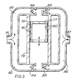
- the double acting pump unit shown in Figure 3 comprises a cylindrical casing 75 of circular cross-section, of which the interior serves as a pumping chamber.
- Plain sleeve bearings 76 guide a cylindrical plunger or piston 77 for reciprocating axial movement within the chamber, which occurs when a stator winding 79 in the wall of the casing 75 is appropriately energised to co-operate with a rotor winding 80 carried by the piston so that the casing and piston function respectively as the stator and rotor of a linear electric motor.
- a suction pipe 81 for the pump unit communicates with two branch pipes 82 each of which communicates with a respective end of the pumping chamber through a respective non-return valve 84.
- the ends of the pumping chamber similarly communicate through respective non-return valves 85 and branch pipes 86 with a discharge pipe 87 for the pump unit.
- the fluid extraction installation of Figure 4 comprises a pipe stack 100 extending down from a wellhead 101 within a well to a perforating zone 102.
- a suction tail pipe 104 communicates a production fluid reservoir in the perforating zone 102 with a first pump unit 105 in accordance with the invention at the lower end of the pipe stack.
- the production fluid is carried upwardly from the pump 105 through one or more like upper pump units 105 to be discharged through a control valve 106 at the wellhead 101.
- the number of series-operating pump units 105 is determined by the required discharge pressure at the wellhead production valve 106.
- the pipe stack 100 comprises pipe stack sections 110 extending between the pump units 105 and connected to them and to each other by connector joints 111.
- the pipe stack configuration allows the transmission along it of both electric and hydraulic power.
- each pipe stack section 110 may comprise an outer transmission pipe 112 and a production pipe 114 positioned concentrically within it. Between the transmission and production pipes, there are located electric conductors 115 for conveying electric power from the wellhead 101 to the pump units 105, three conductors being shown, for conveying a 3-phase supply.
- the conductors 115 are tubular in form and are spaced apart to provide paths 116 for the circulation between them of a fluid medium.
- three concentric tubular conductors 118 have solid insulation between them and the two circulation paths 116 are between the production pipe 114 and the innermost conductor and between the outermost conductor and the transmission pipe 112.
- the fluid medium can be selected according to performance requirements.
- the fluid medium could be water, but a dielectric medium for example a dielectric oil could be employed to provide electrical insulation.
- a dielectric medium for example a dielectric oil could be employed to provide electrical insulation.
- a barrier fluid can provide static pressurization protection and/or a "dead-end" system and/or a desired leakage of well stimulating fluids into the well fluid.
- the fluid can be employed as a controlled power supply, as by varying the static pressure to perform switching or mechanical control operations of seals for example.
- the barrier fluid can be employed in connection with a well logging system to provide a suitable environment for system components, with the signalling effected by way of the supply conductors by multiplexing.
- the dielectric oil can comprise the production oil after suitable refinement.
- the dielectric oil is circulated at a higher pressure than the extraction pressure to avoid leakage of crude oil into the circulating dielectric oil system.
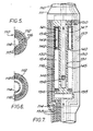
- the connector joints 111 connect pipe stack sections 110 with an outer pipe 130 having concentrically arranged therein concentric inner and outer tubular pump casings 131,132 defining between them an annular pumping chamber 134, closed at its upper end, and communicating at its lower end through non-return valves 135 with the interior of the production pipe 114 of the sub-adjacent pipe stack section.
- the inner pump casing 131 communicates at its upper end with the section of production pipe above the unit 105 and at its lower end with the pumping chamber 134 through a non-return valve 136.
- electrical conductors 137 extend through the unit to effect connection between the conductors 115 or 118 of the adjoining pipe stack sections 110, and ducts 138 similarly provide continuity for the paths 116 for circulation of dielectric oil or other fluid.
- the conductor and fluid path configurations of the pump unit can correspond to either of those shown in Figures 5 and 6.
- Plain sleeve bearings 139 radially align an annular plunger 140 for sliding within the annular pumping chamber 134.
- the plunger 140 is provided with at least one longitudinal channel 141, fitted at its lower end with a non-return valve 142 which functions to prevent "fluid lock" when the plunger is moving upwardly during the filling stroke when production fluid is being drawn upwardly into the chamber 134.
- Linear motor stator windings 145,146 are carried by the casings 131 and/or the casing 132 for co-operation with rotor windings 147,149 provided at the inner and/or the outer peripheral surfaces of the plunger 140.
- A.C. power is supplied from the conductors 137 to the stator winding or windings by take-off lines shown schematically at 150 on the right-hand side of Figure 7.
- This energisation of the stator windings 145,146 causes reciprocation of the plunger 140, functioning as the rotor of the linear motor, so that production fluid is drawn upwardly through the production pipe 114 into the pumping chamber 134 through the non-return valves 135 on the upward stroke. On the downward stroke the fluid in the pumping chamber is forced upwardly along the pipe stack 100 through the non-return valve 136.
- Figure 8 shows a pump unit differing from that of Figure 7, but which can be employed in place of it. Like parts of the pump units of Figures 7 and 8 are indicated by the same reference numerals, the conductors 137 and the fluid paths 116 being indicated schematically.
- the pump unit of Figure 8 contains concentrically within the outer pipe 130 a tubular inner casing 160 defining a cylindrical pumping chamber 161 communicating freely at its upper end with the production pipe 114 of the upper pipe stack section 110, and with the lower production pipe at its lower end through a non-return valve 162.
- a stator winding 164 in the casing 160 surrounds the pumping chamber 161 for co-operation with a rotor winding 165 carried in an annular plunger 166 guided by the plain sleeve bearings 139 for reciprocating movement axially of the chamber.
- the interior of the plunger 166 is closed at its lower end by a non-return valve 167.
- Appropriate energization of the stator winding 164 causes the casing 160 and the plunger 166 to function as the stator and rotor respectively of a linear electric motor, so the plunger reciprocates.
- the upward stroke of the plunger 166 introduces production fluid into the chamber 161 through the non-return valve 162 and the downward stroke expels the fluid upwardly from the chamber through the non-return valve 167.
- the pump units of Figures 3, 7 and 8 may, like that of Figure 2, be modified so that rotor movement takes place within a protective medium, conveniently dielectric oil being circulated along the pipe system.
- the pump unit of Figure 2 can be arranged so that the electromagnetic lifting force equals the weight moved on the suction stroke, as described above with reference to the plunger assembly of Figure 1, and this can apply also to the units of Figures 7 and 8 where the direction of plunger movement is substantially vertical, that is, where the pipe stack is non-deviated. It will be evident that certain other features described in connection with one embodiment can be incorporated in another and the description is to be read accordingly.
Landscapes
- Engineering & Computer Science (AREA)
- Mining & Mineral Resources (AREA)
- Life Sciences & Earth Sciences (AREA)
- Geology (AREA)
- Physics & Mathematics (AREA)
- Fluid Mechanics (AREA)
- Environmental & Geological Engineering (AREA)
- General Life Sciences & Earth Sciences (AREA)
- Geochemistry & Mineralogy (AREA)
- Mechanical Engineering (AREA)
- General Engineering & Computer Science (AREA)
- Reciprocating Pumps (AREA)
- Connection Of Motors, Electrical Generators, Mechanical Devices, And The Like (AREA)
Abstract
Description
- The invention relates to electrically powered pumps or pump units and more specifically to such pumps or pump units in which the pumping action is effected by reciprocating movement of a plunger or pump element within a pumping chamber.
- In known reciprocating pumps, a piston or plunger moves so as to draw the fluid to be pumped from a source into a chamber provided with appropriate valve arrangements and then moves in the opposite direction to expel the fluid to a delivery or discharge outlet. Application of the necessary reciprocating movement to the plunger from a prime mover outside the pump chamber requires a mechanical connection through the chamber wall, and associated sealing means, and where the drive is obtained from a conventional electric motor the rotation drive of the motor shaft has to be converted into the reciprocating movement of the plunger.
- The invention accordingly provides a pump or pump unit having a reciprocably operating pumping element moved by a linear electric motor. The pump unit can have a housing or casing carrying a fixed winding which can be energised from a suitable electric power source to effect reciprocation of a piston or plunger within the casing, so as to function as a positive displacement pump. The reciprocable plunger or piston may be carried by or constituted as the "rotor" or movable part of the linear electric motor, and the casing or housing constitutes the stator or fixed part of the motor.
- The invention can be embodied in pump units having a variety of configurations, but great simplicity can be attained, in particular because the only moving parts are those essential to the pumping action. The pump unit can be said to have, in effect, a driving end without rotating parts.
- A pump unit embodying the invention may be single acting or double acting. It may comprise a tubular casing with a stator winding at the inner surface of its cylindrical side wall, for co-operation with a rotor winding or other conductor carried at the outer periphery of a plunger or piston guided for reciprocable sliding movement axially of the casing to effect pumping through appropriately arranged non-return valves. In order to increase the electromagnetic force acting on the plunger, the casing may include an internal core which carries a second stator winding, the plunger then being annular and having a second rotor winding around its interior curved surface for co-operation with the second stator winding. If preferred, such interior stator and rotor windings can replace the other windings previously described.
- The pumping element or plunger need not be co-extensive with the rotor, but can instead be carried by it so as to project out of a motor casing into a separate pump casing. Such an arrangement facilitates submergence in oil or other protective fluid of the motor casing or driving end to provide environmental protection.
- When a pump unit embodying the invention is to be positioned with the direction of movement of the plunger or rotor substantially vertical, high efficiency can be obtained by arranging the weight of the plunger or rotor assembly and the pumped fluid lifted thereby to equal the capacity of the electric motor, so that the force acting during the pumping stroke is effectively doubled by the addition of the gravitational force.
- Pump units in accordance with the invention can be employed in a variety of ways, in particular as submersible pumps providing relatively small pumping volume with a relatively large pressure head. They can be employed as gas compressor or priming pumps for subsea applications and as electric submerged pumps providing artificial oil lift for small borehole diameters and pumping volumes, in replacement of some "beam-type" pumps.
- The electric power required for operating a pump unit according to the invention could be obtained from solar energy collection equipment to permit the unit to be used for example for lifting water in regions in which other power sources are not readily available.
- The pump units of the invention can also be used as water level control pumps for oil storage caverns, for subsea methanol injection and as leakwater jockey pump
- The invention is further described below, by way of example, with reference to the accompanying drawings, in which:
- Figure 1A is a schematic sectional side view of a first pump unit embodying the invention;
- Figure 1B is a like view of the unit but showing a rotor or plunger assembly therein in elevation and also schematically showing associated control and oil supply means;
- Figure 2 is a schematic sectional side view of a second pump unit embodying the invention;
- Figure 3 schematically shows a double acting pump embodying the invention;
- Figure 4 is a schematic sectional side view of a fluid extraction installation including pump units embodying the invention;
- Figure 5 is a cross-sectional view through a pipe stack section included in the installation of Figure 4, on a larger scale;
- Figure 6 is a view similar to that of Figure 5 of a modified form of pipe stack section;
- Figure 7 is a schematic sectional side view on a still larger scale through a pump unit embodying the invention included in the system of Figure 4; and
- Figure 8 is a schematic sectional side view, also on the still larger scale, of an alternative form of pump unit to that of Figure 7.
- The pump unit shown in Figure 1 has an
upper driving end 2 and a driven orpump end 4 below the driving end. The drivingend 2 comprises a motor casing with aside wall 5 of circular cross-section, closed by anupper end wall 6 from which acentral core 7 of circular cross-section extends downwardly towards alower end wall 9 centrally apertured. A plunger assembly 10 comprises anannular member 11, which is slidable between thecore 7 and asleeve 14 by which theside wall 5 is internally lined, and a plunger 12 which extends downwardly from the annular member and outwardly of the motor casing through a seal provided at the aperture in thelower end wall 9. The plunger 12 is of hollow circular cylindrical form, with a closed end, the interior being a continuation of the interior of theannular member 11. - Plain sleeve bearings (not shown) can act between the
core 7 and the plunger assembly 10 to effect radial alignment of the assembly and to absorb any mechanical imbalances. - The motor casing and the plunger assembly 10 function respectively as the stator and rotor of a linear electric motor. The
sleeve 14 incorporates a stator winding 15 and a stator winding 16 is incorporated in thecore 7 additionally or instead. An outer rotor winding 17 is carried by the annular member for co-operation with the stator winding 15, if provided, and aninner winding 19 is provided for co-operation with the stator winding 16, if this is present. The winding 19 can extend down to the lower end of the plunger interior. - The driven
end 4 has a pump casing with atubular portion 20 aligned with the aperture in thelower end wall 9 and constituting a pump chamber within which the plunger 12 reciprocably moves. Connection of the pump casing to theend wall 9 is by way of aflange 21 at the upper end of thetubular portion 20. A bushing 27 functions as a seal in the end wall aperture and provides a hardened bearing surface to minimise leakage between the driving and driven ends of the pump. At the lower end of the pump casing, thetubular portion 20 is formed with or connected to aligned suction anddischarge pipes 22 and 24, the interiors of which are in communication with the tubular portion interior through appropriately directednon-return valves 25 and 26. - The motor casing is preferably filled with a protective fluid, so as to exclude foreign particles and thus protect the driving end of the unit. The fluid can be a lubricating oil for lubricating the driving end and can be circulated to provide for coating. A filter can be included in the circulation path. Protection against corrosion can be provided for and performance can be monitored by way of the fluid, as by detection of high fluid consumption. The fluid is preferably electrically non-conductive so as to provide electrical insulation. In use of the pump unit in a fluid extraction system, the protective fluid system can be a means of injecting fluid into the well.
- The protective oil or other fluid is necessarily pumped within the motor casing by the reciprocating movement of the plunger assembly 10, and to reduce the resulting friction and pump losses, at least one oversize by-
pass channel 29 is provided in the annular member. Instead, but preferably in addition, an annular by-pass channel 30 is provided in the motor casing, between thewall 5 and thesleeve 14. Achannel 31 furthermore extends within thecore 7, and opens at its lower end. - The oil is conveniently supplied to the motor casing from an accumulator 32 through an
aperture 33 in theside wall 5 to the by-pass channel 30. The accumulator serves to compensate for volume variations during pump operation, and to maintain the protective oil at a relatively constant pressure, higher than the suction pressure of the pumped medium. A bleed-offconnection 35 extends from the centre of the bushing 27 to the suction pipe 22, to ensure that the oil pressure within the motor casing has only to be higher than the relatively low and constant suction pressure. A small quantity of the pumped fluid under high pressure will tend to enter the motor casing during the pumping stroke, but when this reaches thebushing 27 it will be bled off to the suction side by means of thisconnection 35. The accumulator 32 incorporates acooling device 36 andfiltering equipment 37 for re-entering oil. - The small leakage of oil through the
bushing 27 can be made up of an oil supply to the accumulator through asupply pipe 39. Conveniently, electric power is supplied to the pump unit through thepipe 36, the oil providing insulation for the electrical conductors. The supply can be a.c. or d.c. andnecessary supply equipment 40 for regulation or frequency conversion, together withcontrol equipment 41 can be located within the accumulator 32 so that this equipment can be insulated by the protective oil. - An external control system can be provided to control the operation of the unit and to provide signals for remote monitoring of its performance.
- In operation the driving
end 2, is electrically energised by an appropriate a.c. supply from the equipment in the accumulator 32 to reciprocate the plunger assembly 10 and thus effect pumping. The pump unit need not be located in the position illustrated, with the stroke of the plunger assembly 10 substantially vertical, but if it is, the weight of the plunger assembly and of the fluid lifted thereby is preferably arranged to approximate to the electromagnetic force exerted during the suction stroke. The plunger assembly 10 thus acquires potential energy which then doubles the downward force during the pumping stroke. - Alternatively, the acquired potential energy can provide a major part, or the whole, of the force required to effect the pumping stroke. By employing the electrical power input solely for the suction stroke and by relying solely on the release of potential energy for the pumping stroke, the electrical power supply control arrangements can be simplified.
- Depending on the design of the accumulator 32, the pressure of the protective oil will increase when the plunger assembly 10 moves upwardly and this pressure is dissipated at a downward force during the pumping stroke, which reaches a minimum at the end of the stroke.
- Spring means (not shown) may be included to damp the plunger assembly movement and help to reverse this movement at the end of the stroke.
- The pump unit illustrated in Figure 2 comprises a
tubular casing 51 of circular cross-section, with closed ends, the interior of which communicates at its lower end with asuction pipe 52. The lower end of the casing is closed by anend wall 54 from which a centraltubular core 55 extends upwardly. Thecore 55 is hollow and its interior communicates at its lower end with adischarge pipe 56 through aside portion 57. Areturn valve 59 at the upper end of the core interior prevents return of fluid from the discharge pipe into the casing interior. - A
plunger 60 of generally annular shape is slidably received between the core 55 and the casing side wall. Apartition 61 closes the upper end of the plunger interior but has an axial passage containing a non-return interior but has an axial passage containing anon-return valve 62 allowing fluid flow in the downward direction. At least onelongitudinal passage 64 extends through the annular wall of the plunger. - The
casing 51 and theplunger 60 function as the stator and rotor of a linear electric motor of which the stator winding 65 can be provided at the inner side of the casing side wall, for co-operation with a rotor winding 66 at the outer peripheral surface of theplunger 51. Instead, a stator winding 67 can be provided at the outer peripheral surface of thecore 55 for co-operation with a rotor winding 69 at the inner peripheral surface of the plunger, or both co-operating sets of stator and rotor windings can be provided, as shown. - Sleeve bearings or wear rings (not shown) are provided between the
plunger 60 and thecore 55 and between the plunger and thecasing side wall 51. A housing 70 mounted on the top of the casing receives an electrical power supply by way of acable 71 and contains equipment providing appropriate control, regulation and conversion functions as described with reference to the pump unit of Figure 1. - Energisation of the stator winding or windings causes the
plunger 60 to reciprocate within thecasing 51. From its uppermost position shown in Figure 2, downward movement of theplunger 60 causes fluid in the pump chamber constituted by theplunger interior 72 to be discharged to thepipe 56 through thenon-return valve 59 and the core interior. During the following upward movement the fluid to be pumped is drawn into this enlarging chamber from thepipe 52 through thechannel 64 and thenon-return valve 62, for subsequent discharge on the downward stroke. - The plunger/rotor of the unit of Figure 2 moves within the pumped fluid but the linear motor windings must be protected from the pumped fluid and the pressure under which it stands, and the pump unit configuration of Figure 2 can if preferred be modified to incorporate a protective and cooling medium, as with the pump unit of Figure 1. A small quantity of lubricating oil could be supplied at a relatively high pressure to the space between the sleeve bearings to ensure good lubrication and to minimise wear.
- The double acting pump unit shown in Figure 3 comprises a
cylindrical casing 75 of circular cross-section, of which the interior serves as a pumping chamber. Plain sleeve bearings 76 guide a cylindrical plunger orpiston 77 for reciprocating axial movement within the chamber, which occurs when a stator winding 79 in the wall of thecasing 75 is appropriately energised to co-operate with a rotor winding 80 carried by the piston so that the casing and piston function respectively as the stator and rotor of a linear electric motor. - A
suction pipe 81 for the pump unit communicates with twobranch pipes 82 each of which communicates with a respective end of the pumping chamber through a respectivenon-return valve 84. The ends of the pumping chamber similarly communicate through respectivenon-return valves 85 andbranch pipes 86 with adischarge pipe 87 for the pump unit. - On the downward stroke of the
piston 77, fluid in the pumping chamber will be discharged through the lowernon-return valve 85 andbranch pipe 86 to thedischarge pipe 87, whil st the chamber is filled from above through the uppernon-return valve 84. On the upward stroke, the contents of the pump chamber are now expelled through the uppernon-return valve 85 to thedischarge pipe 87, whilst the chamber is filled from below through the lowernon-return valve 84. - The fluid extraction installation of Figure 4 comprises a
pipe stack 100 extending down from awellhead 101 within a well to a perforatingzone 102. Asuction tail pipe 104 communicates a production fluid reservoir in the perforatingzone 102 with afirst pump unit 105 in accordance with the invention at the lower end of the pipe stack. The production fluid is carried upwardly from thepump 105 through one or more likeupper pump units 105 to be discharged through acontrol valve 106 at thewellhead 101. The number of series-operating pump units 105 is determined by the required discharge pressure at thewellhead production valve 106. - The
pipe stack 100 comprisespipe stack sections 110 extending between thepump units 105 and connected to them and to each other by connector joints 111. The pipe stack configuration allows the transmission along it of both electric and hydraulic power. - As shown in Figure 5, each
pipe stack section 110 may comprise anouter transmission pipe 112 and aproduction pipe 114 positioned concentrically within it. Between the transmission and production pipes, there are located electric conductors 115 for conveying electric power from thewellhead 101 to thepump units 105, three conductors being shown, for conveying a 3-phase supply. The conductors 115 are tubular in form and are spaced apart to providepaths 116 for the circulation between them of a fluid medium. - In an alternative conductor configuration of the pipe stack section shown in Figure 6, three concentric tubular conductors 118 have solid insulation between them and the two
circulation paths 116 are between theproduction pipe 114 and the innermost conductor and between the outermost conductor and thetransmission pipe 112. - The fluid medium can be selected according to performance requirements. For cooling, the fluid medium could be water, but a dielectric medium for example a dielectric oil could be employed to provide electrical insulation. In connection with these conductor and fluid circulation arrangements and the various uses to which the latter can be put, reference may be made to European Patent Publication 0 063 444, published on 27 October 1982 on
European Patent Application 82 301 795.9, which discloses also alternative conductor arrangements which could be employed in the present installation. - One or more fluid paths can be provided and can be employed in various further ways. Thus, a barrier fluid can provide static pressurization protection and/or a "dead-end" system and/or a desired leakage of well stimulating fluids into the well fluid. The fluid can be employed as a controlled power supply, as by varying the static pressure to perform switching or mechanical control operations of seals for example. The barrier fluid can be employed in connection with a well logging system to provide a suitable environment for system components, with the signalling effected by way of the supply conductors by multiplexing.
- At the
wellhead 101, there are provided, besides the production fluiddischarge control valve 106,circulation equipment 121 for the dielectric oil and electrical power supply equipment including acontrol device 124 andfrequency converter device 125. Where the illustrated installation is for oil extraction, the dielectric oil can comprise the production oil after suitable refinement. The dielectric oil is circulated at a higher pressure than the extraction pressure to avoid leakage of crude oil into the circulating dielectric oil system. - One of the
pump units 105 is shown in detail in Figure 7. The connector joints 111 connectpipe stack sections 110 with anouter pipe 130 having concentrically arranged therein concentric inner and outer tubular pump casings 131,132 defining between them anannular pumping chamber 134, closed at its upper end, and communicating at its lower end throughnon-return valves 135 with the interior of theproduction pipe 114 of the sub-adjacent pipe stack section. Theinner pump casing 131 communicates at its upper end with the section of production pipe above theunit 105 and at its lower end with thepumping chamber 134 through anon-return valve 136. - Between the
outer pipe 130 and theouter casing 132,electrical conductors 137 extend through the unit to effect connection between the conductors 115 or 118 of the adjoiningpipe stack sections 110, andducts 138 similarly provide continuity for thepaths 116 for circulation of dielectric oil or other fluid. The conductor and fluid path configurations of the pump unit can correspond to either of those shown in Figures 5 and 6. -
Plain sleeve bearings 139 radially align anannular plunger 140 for sliding within theannular pumping chamber 134. Theplunger 140 is provided with at least onelongitudinal channel 141, fitted at its lower end with anon-return valve 142 which functions to prevent "fluid lock" when the plunger is moving upwardly during the filling stroke when production fluid is being drawn upwardly into thechamber 134. - Linear motor stator windings 145,146 are carried by the
casings 131 and/or thecasing 132 for co-operation with rotor windings 147,149 provided at the inner and/or the outer peripheral surfaces of theplunger 140. A.C. power is supplied from theconductors 137 to the stator winding or windings by take-off lines shown schematically at 150 on the right-hand side of Figure 7. - This energisation of the stator windings 145,146 causes reciprocation of the
plunger 140, functioning as the rotor of the linear motor, so that production fluid is drawn upwardly through theproduction pipe 114 into thepumping chamber 134 through thenon-return valves 135 on the upward stroke. On the downward stroke the fluid in the pumping chamber is forced upwardly along thepipe stack 100 through thenon-return valve 136. - Figure 8 shows a pump unit differing from that of Figure 7, but which can be employed in place of it. Like parts of the pump units of Figures 7 and 8 are indicated by the same reference numerals, the
conductors 137 and thefluid paths 116 being indicated schematically. - The pump unit of Figure 8 contains concentrically within the outer pipe 130 a tubular inner casing 160 defining a
cylindrical pumping chamber 161 communicating freely at its upper end with theproduction pipe 114 of the upperpipe stack section 110, and with the lower production pipe at its lower end through anon-return valve 162. - A stator winding 164 in the casing 160 surrounds the
pumping chamber 161 for co-operation with a rotor winding 165 carried in anannular plunger 166 guided by theplain sleeve bearings 139 for reciprocating movement axially of the chamber. The interior of theplunger 166 is closed at its lower end by anon-return valve 167. Appropriate energization of the stator winding 164 causes the casing 160 and theplunger 166 to function as the stator and rotor respectively of a linear electric motor, so the plunger reciprocates. The upward stroke of theplunger 166 introduces production fluid into thechamber 161 through thenon-return valve 162 and the downward stroke expels the fluid upwardly from the chamber through thenon-return valve 167. - The pump units of Figures 3, 7 and 8 may, like that of Figure 2, be modified so that rotor movement takes place within a protective medium, conveniently dielectric oil being circulated along the pipe system. The pump unit of Figure 2 can be arranged so that the electromagnetic lifting force equals the weight moved on the suction stroke, as described above with reference to the plunger assembly of Figure 1, and this can apply also to the units of Figures 7 and 8 where the direction of plunger movement is substantially vertical, that is, where the pipe stack is non-deviated. It will be evident that certain other features described in connection with one embodiment can be incorporated in another and the description is to be read accordingly.
Claims (16)
production piping for conveyance of extracted fluid to the wellhead,
a plurality of the pump units spaced along the pipe stack and having the discharge port of a lower pump unit connected to the suction inlet of an adjacent upper pump unit by the production piping, and
electrical conductors extending along the pipe stack from the wellhead for energizing the linear electric motors of the pump units, the electric conductor means comprising tubular conductors surrounding the production piping and the pump units.
Applications Claiming Priority (2)
| Application Number | Priority Date | Filing Date | Title |
|---|---|---|---|
| GB8600746 | 1986-01-14 | ||
| GB868600746A GB8600746D0 (en) | 1986-01-14 | 1986-01-14 | Electrically powered pump unit |
Publications (2)
| Publication Number | Publication Date |
|---|---|
| EP0237145A2 true EP0237145A2 (en) | 1987-09-16 |
| EP0237145A3 EP0237145A3 (en) | 1988-01-27 |
Family
ID=10591315
Family Applications (1)
| Application Number | Title | Priority Date | Filing Date |
|---|---|---|---|
| EP87300290A Withdrawn EP0237145A3 (en) | 1986-01-14 | 1987-01-14 | Electrically powered pump unit |
Country Status (2)
| Country | Link |
|---|---|
| EP (1) | EP0237145A3 (en) |
| GB (1) | GB8600746D0 (en) |
Cited By (9)
| Publication number | Priority date | Publication date | Assignee | Title |
|---|---|---|---|---|
| EP0310254A3 (en) * | 1987-09-07 | 1990-05-30 | Framo Developments (U.K.) Limited | Reciprocating pump unit |
| DE19611445A1 (en) * | 1995-03-24 | 1996-09-26 | Toyoda Automatic Loom Works | Electrostatic drive device e.g. for gas compressor |
| DE19909279A1 (en) * | 1999-03-03 | 2000-09-07 | Mannesmann Rexroth Ag | Drive for hydraulic consumer e.g. on fork lift truck has electric linear motor driving pump piston |
| WO2001075304A1 (en) * | 2000-04-04 | 2001-10-11 | Baker Hughes Incorporated | Subsea chemical injection pump |
| WO2004016904A1 (en) * | 2002-08-14 | 2004-02-26 | Baker Hughes Incorporated | Subsea chemical injection unit for additive injection and monitoring system for oilfield operations |
| RU2419684C2 (en) * | 2009-06-04 | 2011-05-27 | Учреждение Российской академии наук Институт катализа им. Г.К. Борескова Сибирского отделения РАН | Contact solution, procedure and installation for cleaning surface of metal alloys including surface of cracks and narrow gaps |
| WO2014044334A3 (en) * | 2012-09-18 | 2014-09-18 | Statoil Petroleum As | Improved pump for lifting fluid from a wellbore |
| WO2015172921A1 (en) * | 2014-05-16 | 2015-11-19 | Onesubsea Ip Uk Limited | Downhole equipment suspension and power system |
| CN116641865A (en) * | 2023-04-18 | 2023-08-25 | 卡川尔流体科技(上海)有限公司 | A double-headed plunger pump based on a voice coil direct-acting motor |
Families Citing this family (1)
| Publication number | Priority date | Publication date | Assignee | Title |
|---|---|---|---|---|
| US5676651A (en) | 1992-08-06 | 1997-10-14 | Electric Boat Corporation | Surgically implantable pump arrangement and method for pumping body fluids |
Family Cites Families (6)
| Publication number | Priority date | Publication date | Assignee | Title |
|---|---|---|---|---|
| US2686280A (en) * | 1949-10-25 | 1954-08-10 | Herbert W Strong | Electromagnetic piston pump |
| FR2106841A5 (en) * | 1970-09-25 | 1972-05-05 | Saporta Jose | |
| GB1442737A (en) * | 1974-03-29 | 1976-07-14 | British Petroleum Co | Pumps |
| DE2903817A1 (en) * | 1979-02-01 | 1980-08-07 | Siegfried Dr Ing Kofink | Electromagnetic pump for fluids - has pumping piston fixed to magnetic armature driven by linear motor outside paramagnetic casing of pump |
| JPS57212382A (en) * | 1981-06-23 | 1982-12-27 | Nippon Telegr & Teleph Corp <Ntt> | Ink feeding pump |
| GB2112872A (en) * | 1981-12-10 | 1983-07-27 | British Petroleum Co Plc | Pumping apparatus for installation in wells |
-
1986
- 1986-01-14 GB GB868600746A patent/GB8600746D0/en active Pending
-
1987
- 1987-01-14 EP EP87300290A patent/EP0237145A3/en not_active Withdrawn
Cited By (11)
| Publication number | Priority date | Publication date | Assignee | Title |
|---|---|---|---|---|
| EP0310254A3 (en) * | 1987-09-07 | 1990-05-30 | Framo Developments (U.K.) Limited | Reciprocating pump unit |
| DE19611445A1 (en) * | 1995-03-24 | 1996-09-26 | Toyoda Automatic Loom Works | Electrostatic drive device e.g. for gas compressor |
| US5791883A (en) * | 1995-03-24 | 1998-08-11 | Kabushiki Kaisha Toyoda Jidoshokki Seisakusho | Compressor driver |
| DE19909279A1 (en) * | 1999-03-03 | 2000-09-07 | Mannesmann Rexroth Ag | Drive for hydraulic consumer e.g. on fork lift truck has electric linear motor driving pump piston |
| WO2001075304A1 (en) * | 2000-04-04 | 2001-10-11 | Baker Hughes Incorporated | Subsea chemical injection pump |
| US6663361B2 (en) | 2000-04-04 | 2003-12-16 | Baker Hughes Incorporated | Subsea chemical injection pump |
| WO2004016904A1 (en) * | 2002-08-14 | 2004-02-26 | Baker Hughes Incorporated | Subsea chemical injection unit for additive injection and monitoring system for oilfield operations |
| RU2419684C2 (en) * | 2009-06-04 | 2011-05-27 | Учреждение Российской академии наук Институт катализа им. Г.К. Борескова Сибирского отделения РАН | Contact solution, procedure and installation for cleaning surface of metal alloys including surface of cracks and narrow gaps |
| WO2014044334A3 (en) * | 2012-09-18 | 2014-09-18 | Statoil Petroleum As | Improved pump for lifting fluid from a wellbore |
| WO2015172921A1 (en) * | 2014-05-16 | 2015-11-19 | Onesubsea Ip Uk Limited | Downhole equipment suspension and power system |
| CN116641865A (en) * | 2023-04-18 | 2023-08-25 | 卡川尔流体科技(上海)有限公司 | A double-headed plunger pump based on a voice coil direct-acting motor |
Also Published As
| Publication number | Publication date |
|---|---|
| GB8600746D0 (en) | 1986-02-19 |
| EP0237145A3 (en) | 1988-01-27 |
Similar Documents
| Publication | Publication Date | Title |
|---|---|---|
| US5620048A (en) | Oil-well installation fitted with a bottom-well electric pump | |
| RU2549381C1 (en) | Borehole linear motor | |
| US5960875A (en) | Electric pump having a linear motor | |
| US9482232B2 (en) | Submersible electrical well pump having nonconcentric housings | |
| CA2693311C (en) | Double-acting reciprocating downhole pump | |
| RU2669019C1 (en) | Stage of submersible screw oil well pump with submersible drive | |
| US20080264625A1 (en) | Linear electric motor for an oilfield pump | |
| EP3397866B1 (en) | Electromagnetic coupling for esp motor | |
| CA2934914C (en) | Downhole motor driven reciprocating well pump | |
| RU2677773C2 (en) | Submersible pump installation with linear electric motor, double acting pump and operation method thereof | |
| RU2615775C1 (en) | Borehole pump unit | |
| EP0237145A2 (en) | Electrically powered pump unit | |
| US20160123123A1 (en) | Reciprocating electrical submersible well pump | |
| US20100143166A1 (en) | Downhole pumping system | |
| US20170321711A1 (en) | Isolated thrust chamber for esp seal section | |
| US4406598A (en) | Long stroke, double acting pump | |
| CN106523334A (en) | Oil field downhole mechanical oil extraction device | |
| US20160265521A1 (en) | Pump assemblies | |
| CA2960471C (en) | Refrigeration system with internal oil circulation | |
| EP0310254A2 (en) | Reciprocating pump unit | |
| CN101220806A (en) | High-power oil-submersible linear motor diaphragm pump | |
| RU145258U1 (en) | SUBMERSIBLE LINEAR ELECTRIC MOTOR | |
| GB2112872A (en) | Pumping apparatus for installation in wells | |
| US6857781B1 (en) | Rotor bearing with propeller for increased lubricant flow | |
| RU182645U1 (en) | Modular submersible pump installation |
Legal Events
| Date | Code | Title | Description |
|---|---|---|---|
| PUAI | Public reference made under article 153(3) epc to a published international application that has entered the european phase |
Free format text: ORIGINAL CODE: 0009012 |
|
| AK | Designated contracting states |
Kind code of ref document: A2 Designated state(s): AT BE CH DE ES FR GB GR IT LI LU NL SE |
|
| PUAL | Search report despatched |
Free format text: ORIGINAL CODE: 0009013 |
|
| AK | Designated contracting states |
Kind code of ref document: A3 Designated state(s): AT BE CH DE ES FR GB GR IT LI LU NL SE |
|
| RAP3 | Party data changed (applicant data changed or rights of an application transferred) |
Owner name: FRAMO DEVELOPMENTS (U.K.) LIMITED |
|
| STAA | Information on the status of an ep patent application or granted ep patent |
Free format text: STATUS: THE APPLICATION IS DEEMED TO BE WITHDRAWN |
|
| 18D | Application deemed to be withdrawn |
Effective date: 19880728 |
|
| RIN1 | Information on inventor provided before grant (corrected) |
Inventor name: MOHN, FRANK |