EP0237156B1 - Dispositif de fixation pour une aube de turbine - Google Patents
Dispositif de fixation pour une aube de turbine Download PDFInfo
- Publication number
- EP0237156B1 EP0237156B1 EP87300629A EP87300629A EP0237156B1 EP 0237156 B1 EP0237156 B1 EP 0237156B1 EP 87300629 A EP87300629 A EP 87300629A EP 87300629 A EP87300629 A EP 87300629A EP 0237156 B1 EP0237156 B1 EP 0237156B1
- Authority
- EP
- European Patent Office
- Prior art keywords
- blade
- base
- clamping
- datum
- datum plate
- Prior art date
- Legal status (The legal status is an assumption and is not a legal conclusion. Google has not performed a legal analysis and makes no representation as to the accuracy of the status listed.)
- Expired
Links
Images




Classifications
-
- B—PERFORMING OPERATIONS; TRANSPORTING
- B23—MACHINE TOOLS; METAL-WORKING NOT OTHERWISE PROVIDED FOR
- B23Q—DETAILS, COMPONENTS, OR ACCESSORIES FOR MACHINE TOOLS, e.g. ARRANGEMENTS FOR COPYING OR CONTROLLING; MACHINE TOOLS IN GENERAL CHARACTERISED BY THE CONSTRUCTION OF PARTICULAR DETAILS OR COMPONENTS; COMBINATIONS OR ASSOCIATIONS OF METAL-WORKING MACHINES, NOT DIRECTED TO A PARTICULAR RESULT
- B23Q3/00—Devices holding, supporting, or positioning work or tools, of a kind normally removable from the machine
- B23Q3/02—Devices holding, supporting, or positioning work or tools, of a kind normally removable from the machine for mounting on a work-table, tool-slide, or analogous part
- B23Q3/06—Work-clamping means
- B23Q3/062—Work-clamping means adapted for holding workpieces having a special form or being made from a special material
- B23Q3/063—Work-clamping means adapted for holding workpieces having a special form or being made from a special material for holding turbine blades
-
- B—PERFORMING OPERATIONS; TRANSPORTING
- B24—GRINDING; POLISHING
- B24B—MACHINES, DEVICES, OR PROCESSES FOR GRINDING OR POLISHING; DRESSING OR CONDITIONING OF ABRADING SURFACES; FEEDING OF GRINDING, POLISHING, OR LAPPING AGENTS
- B24B41/00—Component parts such as frames, beds, carriages, headstocks
- B24B41/06—Work supports, e.g. adjustable steadies
-
- Y—GENERAL TAGGING OF NEW TECHNOLOGICAL DEVELOPMENTS; GENERAL TAGGING OF CROSS-SECTIONAL TECHNOLOGIES SPANNING OVER SEVERAL SECTIONS OF THE IPC; TECHNICAL SUBJECTS COVERED BY FORMER USPC CROSS-REFERENCE ART COLLECTIONS [XRACs] AND DIGESTS
- Y10—TECHNICAL SUBJECTS COVERED BY FORMER USPC
- Y10T—TECHNICAL SUBJECTS COVERED BY FORMER US CLASSIFICATION
- Y10T29/00—Metal working
- Y10T29/49—Method of mechanical manufacture
- Y10T29/49316—Impeller making
- Y10T29/49336—Blade making
Definitions
- a plurality of turbine blades are connected with and extend radially from a rotational disk or hub.
- Each blade includes a root form portion which is serrated to fit within similarly configured slots in the disk to lock the blades in place.
- Each turbine blade has a precise configuration, the tolerances of which are determined by the accuracy of the root form.
- the present invention relates to a device for securely holding a turbine blade during machining or grinding of the serrations in the root form.
- the root form may be ground more accurately, thereby improving the tolerances of the entire configuration of the blade.
- the air foil portion of the blade in a mold or matrix block and to fill the mold with molten lead which hardens to form a lead block.
- the root form portion of the blade extends from the lead block, the block is mounted in a fixture, and the serrations are ground in the protruding root form portion of the blade.
- lead blocks A major drawback of the use of lead blocks is that the lead is porous and flexible, even when in the solid state. Thus, the lead block can not be securely held during grinding of the root form, whereby inaccuracies in the root form are developed. Since the root form provides the basis for all of the critical dimensions in the blade, the entire blade will be inaccurate where the root form is not ground to the proper specifications.
- Turbine blade holding devices are also known in the patented prior art as evidenced by the patents to Brenning No. 3,331,166 and Arrigoni No. 4,400,915 and to Martin No 2 887 828. While these devices normally operate satisfactorily, they are designed for machining the air foil portion of the blade rather than the root form portion.
- a major drawback of the prior blade holders is that they are incapable of accurately and securely holding a plurality of successive turbine blades during grinding of the root form portions of the blades, whereby each root form, and thus each bide, will be uniform in dimension and configuration.
- the present invention was developed to overcome these and other drawbacks of the prior devices by providing a holding device which aligns the blade air foil stacking line and the root center line in the proper position at all times. This allows the operator to load the blade, grind the root form, and unload the blade in less time than is necessary with conventional lead mold forming techniques. Moreover, a blade may be accurately reloaded in the holder, if necessary, for additional machining.
- apparatus for securely holding a turbine blade during grinding of the root form portion thereof comprising
- the first and second datum plates are removably connected with the base, and the clamping device is an elongated clamp which extends generally parallel to the blade and which is displaced against the upper surface of the blade upon operation of a torque screw threadedly connected with the base.
- each datum plate includes an upper horizontal edge for supporting the blade sections and an inclined edge against which the blade forward portion is urged owing to the clamping force exerted on the fulcrum of the blade.
- the pin normally extends from the front of the base adjacent the first datum plate to engage a datum point on the shelf portion of the blade.
- the pin may extend from the rear of the base adjacent the second datum plate where the blade contains a shroud having the datum point located thereon.
- Additional clamps may also be connected with the base to further clamp the blade after operation of the torque screw to set the blade in the appropriate position relative to the pin and the datum plates.
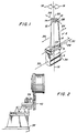
- the blade 2 includes a root form portion 4, a shelf portion 6, an air foil portion 8 having a leading edge 10 and a trailing edge 12, and an optional shroud 14.
- Turbine blades are normally cast as an integral unit.
- Each turbine blade has a stacking axis 16 which corresponds with the centerline of the air foil portion of the blade. Rotation of the air foil about the stacking axis is referred to as twist as shown by the arrows 18. The point at which the stacking axis emerges from the shroud 14 is the stacking point 20.
- a datum point may be located at a predetermined distance from the shroud where the stacking axis enters the same. Where no shroud is provided on the blade, the datum point 22 is located on the shelf at a predetermined distance from where the stacking axis passes therethrough.
- Deflection of the air foil 8 from front to rear relative to the root form 4 is referred to as tilt as shown by the arrows 24.
- Deflection of the air foil from side to side is referred to as lean as shown by the arrows 26.
- a tangent line 28 is that line adjacent the shelf 6 and normal to the stacking axis 16 which is defined between the leading 10 and trailing 12 edges of the air foil section.
- the tangent angle 30 is defined as the angle between the tangent line 28 and a line through the datum point 22 parallel to the root form centerline 32.
- the air foil portion 8 of a turbine blade can be divided into an infinite number of sections which are stacked upon one another.
- the configuration of each section is designated around the stacking point thereof, the stacking point being located along the stacking axis 16 at the location bisected by the horizontal plane through which an individual air foil section is taken.
- the root form portion 4 of the blade is ground to form a plurality of serrations 34.
- the orientation of the serrations is critical to insure that the entire blade is properly arranged in a turbine assembly.
- a turbine assembly (not shown) comprises a plurality of turbine blades connected with and extending radially from a central, rotatable disk.
- the disk contains a plurality of slots or recesses, there being one recess for each blade.
- Each recess is configured to receive the serrated root form of the blade.
- the blades and their root forms must be accurately shaped for cooperation with the other blades of the assembly.
- the shrouds of adjoining blades are designed to be in contiguous relation to each other.
- the orientation and configuration of the root form serrations are critical.
- the holding device 36 of the present invention is shown mounted in a fixed orientation on a table 38 or the like adjacent a grinding wheel 40.
- the rotating grinding wheel may be displaced relative to a turbine blade root form secured in the holder 36 in a conventional manner to grind the root form in order to form the serrations therein.
- a plurality of turbine blade holding devices 36 may be arranged in parallel opposite the grinding wheel 40.
- the wheel may be reciprocated adjacent the plurality of turbine blade holders to accurately machine or grind a plurality of root forms substantially simultaneously.
- the turbine blade holder includes a fixed base 42 having a front datum plate 44 and a rear datum plate 46 removably connected therewith.
- the datum plates may easily be replaced after they have become worn, whereby the down time of the holder is minimized.
- the front datum plate 44 supports the leading 10 and trailing 12 edges of a section of the turbine blade air foil portion 8 adjacent the shelf 6.
- the datum plate includes in the upper surface thereof a pair of horizontal knife-like support edges 48, 50 as shown in Figs. 5 and 5a for supporting the leading and trailing edges, respectively, of the blade.
- the front datum plate 44 also includes an inclined knife edge 52 against which the forward portion 8a of the air foil abuts.
- the rear datum plate 46 includes a horizontal knife edge 54 for supporting the leading edge of a remote section of the blade as shown in Figs. 3, 6, and 6a. Owing to the configuration of the air foil portion of the blade, the trailing edge of the blade at the remote section thereof is not supported by the datum plate 46.
- the rear datum plate also includes an inclined knife edge 56 adjacent the horizontal support edge 54 against which the forward portion 8a of the air foil abuts, as will be developed in greater detail below.
- a pin 58 Extending horizontally from and connected with the base is a pin 58.
- a turbine blade When a turbine blade is longitudinally arranged on the base, its air foil portion 8 is supported on the front and rear datum plates and the datum point 22 on the blade shelf portion 16 is aligned with and engages the pin 58.
- a clamping mechanism is connected with the base 42 to clamp the turbine blade against the datum plates and the pin.
- a clamp arm 60 is pivotally connected with the base 42 by a horizontally extending dowel 62 and a pair of spacing elements 64.
- a pivot clamp 66 is connected with the clamp arm by a swivel screw 68 which allows the clamp 66 to pivot relative to the clamp arm in both the longitudinal and lateral directions, i.e. from front to back and from side to side relative to the base 42.
- a top plate 70 is connected with the base 42 above the clamp arm 60 as shown in the drawing.
- the top plate includes a threaded aperture located above the remote end of the clamp arm 60 which is adapted to receive a torque screw 72.
- the top plate also includes a through opening above the near end of the clamp arm 60 which is adapted to receive a spring 74. The spring normally biases the near end of the clamp arm 60 downwardly, whereby the remote end of the clamp arm is pivoted upwardly as the arm pivots about the dowel 62.
- the characterizing feature of the clamping mechanism set forth above is that the clamp 66 extends longitudinally in the direction of the air foil portion 8 of the blade and contacts the convex surface of the air foil along the fulcrum thereof.
- the torque screw 72 As the torque screw 72 is rotated in one direction, its lower end pushes the remote end of the clamp arm 60 downwardly to pivot the clamp arm against the biasing force of the spring 74.
- the pivot clamp 66 is brought into contact with the blade air foil portion and pivots longitudinally and laterally to rest flush along the air foil convex surface. Further rotation of the torque screw 72 increases the clamping force applied to the air foil by the pivot clamp.
- the clamping force represented by the arrow A in Figs. 5 and 6, is through the fulcrum of the blade air foil section, the first section of the air foil is clamped against the horizontal edges 48, 50 and the inclined edge 52 of the front datum plate 44 and the rear section of the air foil is clamped against the horizontal 54 and inclined 56 edges of the rear datum plate 46.
- the air foil is also fixed with its datum point aligned and in engagement with the pin 58 extending from the base 42.
- the serrations may be accurately ground in the root form portion 4 thereof.
- the torque screw 72 is rotated in the opposite direction to raise the clamp arm 60 which in turn raises the pivot clamp 66 away from the blade air foil portion.
- the blade may then be removed and a subsequent blade quickly inserted for machining of its root form.
- a previously machined blade may also be re-inserted into the holding device and accurately held in the same position as originally held since the blade will be located and clamped against the same section and datum points as before.
- the present holding device is designed for locating and securing each blade relative to its stacking axis. Accordingly, the location of the pin 58 and the datum plates 44 and 46 relative to the pin is critical for each size and configuration of blade. Separate holding devices may thus be designed for blades having different sizes and configurations. In accordance with the present invention, however, all blades of a given size and configuration will be precisely held in the same location, whereby the serrations ground in the root form portions thereof will practically be identical. In this manner, all of the blades of a particular turbine assembly having blades of a given size and configuration will be within acceptable tolerance.
- additional clamps may be provided to further secure the turbine blade once the pivot clamp has been pressed against the fulcrum of the blade air foil section.
- a spring clamp may be connected with the base 42 to further secure the blade at the shelf portion thereof.
- the spring clamp includes a generally L-shaped clamp 76, the longer leg 78 of which passes through a longitudinal opening in the base 42.
- a spring 80 fits over the remote end of the leg 78 adjacent the rear of the base, and a locking knob 82 is connected with the remote end of the leg 78 to secure and release the spring clamp.
- a dead clamping mechanism is also provided to press the blade against the pin 58.
- the dead clamp includes a clamp arm 84 which pivots about a vertically extending dowel 86 which is arranged in a vertical opening in the base 42.
- a second top plate 88 is connected with the base and also contains a vertical opening to receive the dowel 86.
- the second top plate also contains an inclined opening adapted to receive a spring 90 which biases the clamp arm 84 in one direction of rotation about the vertical dowel 86.
- a torque screw 92 is connected with one end of the clamp arm and with the base to control the pivotal movement of the clamp arm 86 about the dowel.
- the opposite end of the clamp arm 84 is adapted to engage the shelf portion of the blade. Operation of screw 92 to rotate the arm in a clockwise direction forces the arm against the blade to press it against the pin 58.
- An auxiliary clamping mechanism for the remote portion of an unshrouded turbine blade may also be provided for clamping the end of the air foil portion between its convex and concave surfaces.
- a base block 94 is pivotally connected with the base 42 of the holding device via a vertically arranged dowel 96 which passes through aligned openings in the base 42 and block 94.
- a pivot 98 is connected with the base block 94.
- the pivot block includes a threaded vertical extension 100 which passes through a vertical opening in the block 94 and to which a nut 102 is connected.
- a spring 104 is arranged between the pivot block 98 and the base block 94.
- a clamp arm 106 is pivotally connected with the pivot block 98 via a horizontal laterally extending dowel 108.
- a first contact 110 is connected with the remote end of the clamp arm 106 and is adapted to contact the concave surface of the blade air foil portion.
- a second contact 112 is connected with the pivot block 98 and is adapted to contact the convex surface of the blade air foil portion.
- a torque screw 114 is threadably connected with a vertical threaded opening in the base block 94, with the lower portion of the screw engaging the clamp arm 106. Rotation of the screw 114 pivots the arm 106 about the dowel 108 to bring the contacts 110 and 112 into clamping engagement with the opposite surfaces of the blade air foil portion.
- the turbine blade holding device may also be designed for securing turbine blades including a shroud portion 14 as shown in the embodiment of Fig. 4 wherein like reference numerals indicate elements corresponding with those of the embodiment of Fig. 3.
- the turbine blade holder includes a base 42 having front 44 and rear 46 datum plates removably connected with the base by any suitable means such as bolts not shown.
- the front and rear datum plates support the leading and trailing edges of the air foil portion 8 of a turbine blade in the same manner as discussed with the embodiment of Fig. 3.
- the pin 58 of the holder of the embodiment of Fig. 4 is relocated to extend longitudinally horizontally from the rear of the base to abut against the datum point of the blade located on the shroud portion 14 thereof.
- the base 42 includes a clamp yoke block 116 having aligned longitudinal openings to receive the dowel 62 about which the clamp arm 60 rotates. Spacers 64 space the clamp arm relative to the yoke block 116.
- the pivot clamp 66 is connected with the remote end of the arm 60 by a swivel screw connection 68.
- the spring 74 biases the arm and clamp 66 away from the surface of the blade air foil portion and the torque screw 72 controls the displacement of the clamping arm to control the clamping force applied to the fulcrum of the blade.
- a set screw 118 controls the biasing force of the spring 74.
- the base 42 includes a block portion 120 which is connected with the base via a torque screw 122.
- the torque screw passes through aligned openings in the block 120 and the rear datum plate 47 and into a threaded opening (not shown) in the rear of the base. Tightening of the tension screw 120 forces the block against the shroud portion 14 of the blade which in turn is forced against the pin 58.
- a spring 124 is connected with the front datum plate 44 and is compressed against the shelf portion 6 of the blade. Once secure, the root form portion of the blade is ground to accurately form the serrations in the manner set forth above.
- the turbine blade holding device of Fig. 7 is similar to that of Fig. 3, but for the blade clamping mechanism and the datum plates. Accordingly, like reference numerals have been used for the same elements of the holder of Fig. 3. in addition to the clamp arm 60, the holder of the embodiment of Fig. 7 includes a pair of auxiliary arms 130 pivotally connected with the base 42 by a pin (not shown) and spaced by spacers 132. At the free end of each auxiliary arm 130 is pivotally connected a contact plate 134. A pair of springs 74 normally bias the near ends of the auxiliary arms downwardly, whereby the remote or free ends thereof are pivoted upwardly, respectively.
- the pivot clamp 66 pushes the remote ends of the auxiliary arms downwardly against the biasing force of the springs 74.
- the contact plates 134 are thus brought into contact with the blade air foil portion and pivot laterally to rest flush against the air foil convex surface. The contact plates thereby apply a clamping force through the fulcrum of the blade to clamp it against the front datum plate 136 and the rear datum plate 138 as shown more particularly in Figs. 8-11.
- FIGs. 8-11 An alternate datum plate design, adapted particularly for use with air foil blades whose thickness varies, is shown in Figs. 8-11. These datum plates may be used to grind the root form on the airfoil regardless of the blade thickness as cast.
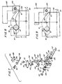
- Figs. 8 and 9 show a front datum plate 136 utilizing 45 ° angle contacts to support the leading 10 and trailing 12 edges of the airfoil blade.
- the blade is shown in the solid line 8 having a maximum thickness and in the broken line 8a having a minimum thickness. Owing to the contact plate 134 which is pivotally connected with the auxiliary arms 130, blades of both maximum and minimum thickness are accurately held against the datum plate.
- the distance X represents the set up dimension for the root form grinding operation relative to the root form centerline.
- Y represents the offset of the stacking point for the blade of minimum thickness relative to the blade of maximum thickness, which offset is accomodated by the datum plate design and by the pivotal contact plates, each of which contact the blade air foil at two locations as shown in Figs. 8 and 9.
- Figs. 10 and 11 show the rear and front datum plates 138, 136 of the embodiment of Fig. 7. These datum plates locate the turbine blade at the leading edge 10 in knife edge support surfaces 140, 142 arranged at 90 ° relative to each other and normal to the blade extended root centerline 32. The trailing edgel2 of the blade rests on a knife edge support surface 144 on a 45 ° angle parallel to the leading edge support surface 140.
- the rear datum plate 138 of Fig. 10 is similar to the front plate but does not have a support surface for the blade trailing edge as in the case with the rear datum plate 46 of Fig. 6.
- Figs. 12 and 13 illustrate the rear and front datum plates 146, 148 of yet another plate design. These plates are for locating a turbine blade at the leading edge between support surfaces arranged at 90 ° relative to each other as in the design of Figs. 10 and 11.
- the front plate 148 supports the blade trailing edge 12 on a support surface 150 in a plane parallel with the root form centerline 32.
- the turbine blade holding device is preferably formed of a durable metal such as iron or stainless steel.
- the height of the horizontal support edges of the datum plates relative to the stacking axis of the blade, the spacing of the datum plates relative to the pin, and the location of the inclined support edge of the datum plates are all predetermined, either by calculations from a turbine blade or from settings provided by the manufacturer of the blade.
Landscapes
- Engineering & Computer Science (AREA)
- Mechanical Engineering (AREA)
- Electrical Discharge Machining, Electrochemical Machining, And Combined Machining (AREA)
- Turbine Rotor Nozzle Sealing (AREA)
- Jigs For Machine Tools (AREA)
Claims (18)
Applications Claiming Priority (2)
| Application Number | Priority Date | Filing Date | Title |
|---|---|---|---|
| US838943 | 1986-03-12 | ||
| US06/838,943 US4638602A (en) | 1986-01-03 | 1986-03-12 | Turbine blade holding device |
Publications (2)
| Publication Number | Publication Date |
|---|---|
| EP0237156A1 EP0237156A1 (fr) | 1987-09-16 |
| EP0237156B1 true EP0237156B1 (fr) | 1989-10-18 |
Family
ID=25278454
Family Applications (1)
| Application Number | Title | Priority Date | Filing Date |
|---|---|---|---|
| EP87300629A Expired EP0237156B1 (fr) | 1986-03-12 | 1987-01-26 | Dispositif de fixation pour une aube de turbine |
Country Status (5)
| Country | Link |
|---|---|
| US (1) | US4638602A (fr) |
| EP (1) | EP0237156B1 (fr) |
| JP (1) | JPS62228601A (fr) |
| CA (1) | CA1265168A (fr) |
| DE (1) | DE3760784D1 (fr) |
Families Citing this family (40)
| Publication number | Priority date | Publication date | Assignee | Title |
|---|---|---|---|---|
| US4805351A (en) * | 1988-02-08 | 1989-02-21 | Avco Corporation | Blade airfoil holding system |
| US4829720A (en) * | 1988-06-20 | 1989-05-16 | Cavalieri Dominic A | Turbine blade positioning fixture |
| FR2643940B1 (fr) * | 1989-03-01 | 1991-05-17 | Snecma | Aube mobile de turbomachine a moment de pied compense |
| USD375238S (en) | 1995-05-26 | 1996-11-05 | Universal Consolidated Methods, Inc. | Clamp |
| FR2740273B1 (fr) * | 1995-10-18 | 1997-11-21 | Electricite De France | Dispositif de pose de balises aeriennes sur un cable |
| US6017263A (en) * | 1996-04-30 | 2000-01-25 | United Technologies Corporation | Method for manufacturing precisely shaped parts |
| US6139412A (en) * | 1996-04-30 | 2000-10-31 | United Technologies Corporation | Fixture for manufacturing precisely shaped parts |
| US5869194A (en) * | 1996-04-30 | 1999-02-09 | United Technologies Corporation | Blank for manufacturing precisely shaped parts |
| US6068541A (en) | 1997-12-22 | 2000-05-30 | United Technologies Corporation | Method for using a fixture enabling more accurate machining of a part |
| FR2817783B1 (fr) * | 2000-12-07 | 2003-02-21 | Snecma Moteurs | Outillage de maintien d'une aube, et son application au soudage par friction des aubes |
| US6426622B1 (en) * | 2000-12-21 | 2002-07-30 | General Electric Company | Fixture for eddy current inspection probes |
| US6844515B2 (en) * | 2001-10-10 | 2005-01-18 | Brett Wayne Byrnes | Method and apparatus for turbine blade machining |
| US6568993B1 (en) | 2001-12-13 | 2003-05-27 | General Electric Company | Fixture for clamping a gas turbine component and its use in shaping the gas turbine component |
| US6652369B2 (en) | 2001-12-13 | 2003-11-25 | General Electric Company | Fixture for clamping a gas turbine component and its use in shaping the gas turbine component |
| US6855033B2 (en) * | 2001-12-13 | 2005-02-15 | General Electric Company | Fixture for clamping a gas turbine component blank and its use in shaping the gas turbine component blank |
| US6627833B2 (en) | 2002-01-30 | 2003-09-30 | United Technologies Corporation | Fixture for securing a workpiece |
| US6560890B1 (en) * | 2002-02-21 | 2003-05-13 | General Electric Company | Fixture for locating and clamping a part for laser drilling |
| US6761807B2 (en) * | 2002-03-09 | 2004-07-13 | United Technologies Corporation | Molded tooling for use in airfoil stripping processes |
| US6890248B2 (en) * | 2003-02-28 | 2005-05-10 | General Electric Company | Apparatus and method for consistently retaining a gas turbine engine blade in a predetermined position and orientation |
| JP4254352B2 (ja) * | 2003-06-04 | 2009-04-15 | 株式会社Ihi | タービンブレード |
| US7328496B2 (en) * | 2003-10-31 | 2008-02-12 | General Electric Company | Apparatus for rebuilding gas turbine engine blades |
| US7334306B2 (en) * | 2004-06-02 | 2008-02-26 | General Electric Company | Methods and apparatus for fabricating a turbine nozzle assembly |
| US7752755B2 (en) * | 2005-10-14 | 2010-07-13 | General Electric Company | Methods and apparatus for manufacturing components |
| JP5013292B2 (ja) * | 2008-01-24 | 2012-08-29 | 平和産業株式会社 | タービンブレードの固定装置 |
| US8151458B2 (en) * | 2008-02-21 | 2012-04-10 | United Technologies Corporation | Non-metallic cover for a fixture |
| GB2459878B (en) * | 2008-05-09 | 2010-12-29 | Rolls Royce Plc | Clamping system |
| US9687926B2 (en) * | 2009-04-03 | 2017-06-27 | United Technologies Corporation | Trailing edge machining of a workpiece |
| FR2956996B1 (fr) * | 2010-03-05 | 2012-06-01 | Snecma | Dispositif de maintien d'une aube par sa pale lors de l'usinage de son pied |
| CN102029537B (zh) * | 2010-11-11 | 2012-08-29 | 西北工业大学 | 薄壁叶片数控加工精密定位夹具 |
| CN102145465B (zh) * | 2011-04-15 | 2012-11-07 | 杭州中水水力发电设备有限公司 | 叶片加工万能装夹工装 |
| DE102011089699B4 (de) * | 2011-12-22 | 2013-09-12 | Lufthansa Technik Ag | Vorrichtung zum Rekonturieren einer Gasturbinenschaufel |
| SG2013002183A (en) | 2013-01-10 | 2014-08-28 | Pratt & Whitney Services Pte Ltd | Turbine shroud milling with blade held in same fixture during milling of concave and convex parts |
| CN103223606A (zh) * | 2013-05-16 | 2013-07-31 | 西北工业大学 | 一种叶片数控加工精密定位的通用夹具 |
| CN103846706B (zh) * | 2014-03-20 | 2016-04-20 | 西北工业大学 | 一种叶片类零件铣削专用拉紧夹具 |
| CN107838719B (zh) * | 2017-12-04 | 2023-04-28 | 无锡透平叶片有限公司 | 用于压气机叶片燕尾型叶根加工的夹具 |
| CN110480461B (zh) * | 2019-08-30 | 2020-05-19 | 成都和鸿科技有限公司 | 重型燃气轮机动叶榫头集成加工用夹具及其集成加工方法 |
| CN111360622B (zh) * | 2020-03-20 | 2021-04-06 | 许昌学院 | 风力发电用叶片加工设备 |
| CN112589749A (zh) * | 2020-11-24 | 2021-04-02 | 太仓治誓机械设备科技有限公司 | 一种水力发电站水轮机组的高速叶片安装固定机构 |
| CN116512127B (zh) * | 2023-06-16 | 2025-11-11 | 贵州乾鼎科技发展有限公司 | 一种航空发动机高压涡轮叶片磨削固定工装 |
| CN119703577A (zh) * | 2025-02-17 | 2025-03-28 | 中国航发北京航空材料研究院 | 涡轮叶片耐磨层堆焊用定位夹持装置 |
Family Cites Families (9)
| Publication number | Priority date | Publication date | Assignee | Title |
|---|---|---|---|---|
| US2565925A (en) * | 1946-04-10 | 1951-08-28 | Rolls Royce | Method of manufacturing guide vanes for axial flow turbines and compressors |
| US2578531A (en) * | 1948-08-14 | 1951-12-11 | Jones & Lamson Mach Co | Machine for grinding impeller bucket shanks |
| US2887828A (en) * | 1956-09-06 | 1959-05-26 | Norton Co | Grinding machine |
| US3331166A (en) * | 1964-11-27 | 1967-07-18 | Brenning Albert | Jig for grinding turbine blades of jet engines |
| US3818646A (en) * | 1973-01-12 | 1974-06-25 | Trw Inc | Fixture for holding precisely shaped parts |
| US4033569A (en) * | 1976-10-15 | 1977-07-05 | Dunn Garf L | Deformation-preventing workpiece-holding fixture for machine tools |
| US4128929A (en) * | 1977-03-15 | 1978-12-12 | Demusis Ralph T | Method of restoring worn turbine components |
| US4400915A (en) * | 1980-06-02 | 1983-08-30 | United Technologies Corporation | Fixture for restoring a face on the shroud of a rotor blade |
| US4589175A (en) * | 1980-06-02 | 1986-05-20 | United Technologies Corporation | Method for restoring a face on the shroud of a rotor blade |
-
1986
- 1986-03-12 US US06/838,943 patent/US4638602A/en not_active Expired - Fee Related
-
1987
- 1987-01-26 EP EP87300629A patent/EP0237156B1/fr not_active Expired
- 1987-01-26 DE DE8787300629T patent/DE3760784D1/de not_active Expired
- 1987-01-26 JP JP62014310A patent/JPS62228601A/ja active Pending
- 1987-01-27 CA CA000528302A patent/CA1265168A/fr not_active Expired
Also Published As
| Publication number | Publication date |
|---|---|
| US4638602A (en) | 1987-01-27 |
| DE3760784D1 (en) | 1989-11-23 |
| EP0237156A1 (fr) | 1987-09-16 |
| JPS62228601A (ja) | 1987-10-07 |
| CA1265168A (fr) | 1990-01-30 |
Similar Documents
| Publication | Publication Date | Title |
|---|---|---|
| EP0237156B1 (fr) | Dispositif de fixation pour une aube de turbine | |
| US4829720A (en) | Turbine blade positioning fixture | |
| US4805351A (en) | Blade airfoil holding system | |
| US4128929A (en) | Method of restoring worn turbine components | |
| US4759153A (en) | Method and apparatus for sharpening a serrated cutting edge | |
| US3788633A (en) | Adjustable angle plate arrangement | |
| US3331166A (en) | Jig for grinding turbine blades of jet engines | |
| US20010034951A1 (en) | Alignment tool apparatus and method | |
| US7056195B2 (en) | Apparatus and method for sharpening tool blades | |
| US4690023A (en) | Clamping mechanism for a cutter of a microtome | |
| US2811873A (en) | Chain saw grinding machine | |
| CN110434639B (zh) | 一种用于叶片的自动定心装置及其方法 | |
| US5142946A (en) | Sharpener for circular saws | |
| CN214844715U (zh) | 一种新型涂层划格测试仪 | |
| US4446760A (en) | Saw blade clamp | |
| US3373530A (en) | Sharpening fixture for twist drills | |
| US1852276A (en) | Apparatus for dressing circular saws | |
| CN211516917U (zh) | 一种刀刃单侧磨削装置 | |
| USRE21877E (en) | Tool holder | |
| US3759118A (en) | Circular saw grinding attachment | |
| JPS58175631A (ja) | 射出成型部品のゲ−ト切断装置 | |
| CN112881281A (zh) | 一种新型涂层划格测试仪 | |
| US4124157A (en) | Brazing fixture | |
| GB2151368A (en) | Clamping mechanism for a cutter of a microtome | |
| CN114269531A (zh) | 带有斜面枢转轴线对准布置结构的台锯 |
Legal Events
| Date | Code | Title | Description |
|---|---|---|---|
| PUAI | Public reference made under article 153(3) epc to a published international application that has entered the european phase |
Free format text: ORIGINAL CODE: 0009012 |
|
| AK | Designated contracting states |
Kind code of ref document: A1 Designated state(s): DE FR GB IT |
|
| 17P | Request for examination filed |
Effective date: 19870824 |
|
| 17Q | First examination report despatched |
Effective date: 19890112 |
|
| GRAA | (expected) grant |
Free format text: ORIGINAL CODE: 0009210 |
|
| AK | Designated contracting states |
Kind code of ref document: B1 Designated state(s): DE FR GB IT |
|
| ITF | It: translation for a ep patent filed | ||
| ET | Fr: translation filed | ||
| REF | Corresponds to: |
Ref document number: 3760784 Country of ref document: DE Date of ref document: 19891123 |
|
| PLBE | No opposition filed within time limit |
Free format text: ORIGINAL CODE: 0009261 |
|
| STAA | Information on the status of an ep patent application or granted ep patent |
Free format text: STATUS: NO OPPOSITION FILED WITHIN TIME LIMIT |
|
| 26N | No opposition filed | ||
| ITTA | It: last paid annual fee | ||
| PGFP | Annual fee paid to national office [announced via postgrant information from national office to epo] |
Ref country code: GB Payment date: 19920127 Year of fee payment: 6 |
|
| PGFP | Annual fee paid to national office [announced via postgrant information from national office to epo] |
Ref country code: FR Payment date: 19920131 Year of fee payment: 6 |
|
| PGFP | Annual fee paid to national office [announced via postgrant information from national office to epo] |
Ref country code: DE Payment date: 19920228 Year of fee payment: 6 |
|
| PG25 | Lapsed in a contracting state [announced via postgrant information from national office to epo] |
Ref country code: GB Effective date: 19930126 |
|
| GBPC | Gb: european patent ceased through non-payment of renewal fee |
Effective date: 19930126 |
|
| PG25 | Lapsed in a contracting state [announced via postgrant information from national office to epo] |
Ref country code: FR Effective date: 19930930 |
|
| PG25 | Lapsed in a contracting state [announced via postgrant information from national office to epo] |
Ref country code: DE Effective date: 19931001 |
|
| REG | Reference to a national code |
Ref country code: FR Ref legal event code: ST |
|
| PG25 | Lapsed in a contracting state [announced via postgrant information from national office to epo] |
Ref country code: IT Free format text: LAPSE BECAUSE OF NON-PAYMENT OF DUE FEES;WARNING: LAPSES OF ITALIAN PATENTS WITH EFFECTIVE DATE BEFORE 2007 MAY HAVE OCCURRED AT ANY TIME BEFORE 2007. THE CORRECT EFFECTIVE DATE MAY BE DIFFERENT FROM THE ONE RECORDED. Effective date: 20050126 |