EP0237161A2 - Procédé et appareil pour le bombage des fonds de boîtes - Google Patents
Procédé et appareil pour le bombage des fonds de boîtes Download PDFInfo
- Publication number
- EP0237161A2 EP0237161A2 EP87300725A EP87300725A EP0237161A2 EP 0237161 A2 EP0237161 A2 EP 0237161A2 EP 87300725 A EP87300725 A EP 87300725A EP 87300725 A EP87300725 A EP 87300725A EP 0237161 A2 EP0237161 A2 EP 0237161A2
- Authority
- EP
- European Patent Office
- Prior art keywords
- dome
- bottom wall
- forming ring
- domer die
- forming
- Prior art date
- Legal status (The legal status is an assumption and is not a legal conclusion. Google has not performed a legal analysis and makes no representation as to the accuracy of the status listed.)
- Ceased
Links
Images


Classifications
-
- B—PERFORMING OPERATIONS; TRANSPORTING
- B21—MECHANICAL METAL-WORKING WITHOUT ESSENTIALLY REMOVING MATERIAL; PUNCHING METAL
- B21D—WORKING OR PROCESSING OF SHEET METAL OR METAL TUBES, RODS OR PROFILES WITHOUT ESSENTIALLY REMOVING MATERIAL; PUNCHING METAL
- B21D22/00—Shaping without cutting, by stamping, spinning, or deep-drawing
- B21D22/20—Deep-drawing
- B21D22/30—Deep-drawing to finish articles formed by deep-drawing
Definitions
- the present invention relates generally to apparatus for doming the bottom walls of cans and, more particularly, to apparatus for doming thin walled aluminum can bodies of the type having a cylindrical side wall and an integrally formed bottom wall.
- Metal containers such as cans which are adapted to hold contents under pressure are often provided with a upwardly extending dome in the bottom wall thereof to resist the tendency of the bottom wall to deform excessively under pressure and also to provide a generally planar annular portion at the periphery of the bottom wall which provides a stable support base for the can.
- Numerous domed containers are described in prior art patents such as U.S. Patent No. 1,963,795; 3,904,069; and 4,037,752.
- crease lines are probably formed as a result of non-uniform deformation of the can bottom wall at the time it is initially contacted by a dome-shaped die assembly.
- the non-uniform deformation may be due to the fact that the die assembly initially makes a point contact at the center of the can bottom resulting in an initial deformation of the can bottom into a conical configuration. It is in the transition of the can bottom from a generally planar shape to such a conical shape that radial creasing of the can bottom takes place.
- Such a creased dome configuration is generally known in the art as a "flower dome".
- a problem with flower dome formation other than the generally aesthetically unacceptable appearance, is that the crease lines may rupture or weaken the can bottom and may cause leaks or non-uniform deformation of the can bottom when the can is pressurized.
- Another problem associated with dome formation in integrally formed thin walled can bodies is that the deformation of the can bottom wall during doming tends to cause metal flow from the can lateral side wall to the can bottom wall resulting in a slight axial shortening of the can.
- One prior art technique for eliminating these problems has been to tightly engage a peripheral portion of the can bottom wall and a lower portion of the can side wall between a bodymaker punch assembly and a pressure ring during dome formation.
- Such a peripheral engagement of the can wall tends to stabilize the bottom wall circumferentially, thereby reducing the tendency of the bottom wall to crease during dome formation. Such a peripheral engagement also tends to limit the flow of metal from the can side wall to the can bottom wall.
- Another prior art method, sometimes used in combination with a pressure ring, for eliminating flower dome formation is application of relatively high pressure to the domed region of the bottom wall during dome formation to "iron out” any creases that may have been formed during the initial portion of the doming operation.
- a problem with the former technique is that, in applying sufficient pressure to the periphery of the can bottom to prevent the undesirable effects of can shortening and flower dome formation, the engaged portion of the can bottom is sometimes damaged by the pressure ring.
- a problem with "ironing out" radial creases is that the ironed out creased area has different strength and deformation characteristics than the other portions of dome. Furthermore, such ironing out techniques are not always successful in removing all of the radial creases.
- the present invention may comprise a can doming assembly for producing a dome in the bottom wall of a can body of the type having an open top, a cylindrical sidewall and a generally planar bottom wall integrally formed with the sidewall, the sidewall and bottom wall each having an interior surface and an exterior surface, comprising: punch means insertable into the can body through the open top thereof and engageable with the interior surface of the can bottom wall at a peripheral portion of the can bottom wall for urging the can bottom wall against a forming ring means and a domer die means; forming ring means positioned axially adjacent said punch means for deformingly engaging the exterior surface of the can bottom wall at a circular band portion thereof for forming an outer peripheral portion of a dome in the can bottom wall; domer die means positioned axially adjacent said forming ring means for engaging the exterior surface of the can bottom wall at a central circular portion thereof for forming a central portion of a dome in the can bottom wall; ram means attached to said punch means for reciprocally moving said punch means in a first direction toward said
- the present invention may also include a method of forming a dome in the bottom of a can body comprising the steps of: deformably engaging a portion of the can bottom associated with an outer peripheral portion of the dome to be formed with an annular surface having substantially the same shape as the outer peripheral portion of the dome to be formed; subsequently engaging a portion of the can associated with an inner portion of the dome to be formed with a separate spheroid surface of substantially the same shape as the inner portion of the dome to be formed; continually applying pressure to an outer peripheral portion of the can bottom during deforming engagement of said can bottom by both said annular surface and said spheroid surface.
- the present invention may also include a can body comprising: a generally cylindrical sidewall; and a bottom wall integrally formed with said sidewall having an outwardly concave dome therein having a peripheral dome surface formed by an annular forming surface and a central dome surface formed by a separate spheroid forming surface.
- a can doming device of the prior art is represented schematically in Fig. 1.
- a can body 10 to be domed has an open top end 11 defining a circular opening, a cylindrical side wall 12 and a closed circular bottom wall 14 integrally connected to the side wall at a relatively small radius annular shoulder portion 13.
- the can body 10 is mounted about an axially extending cylindrical bodymaker punch 20 of approximately the same external diameter as the internal diameter of the can.
- the bodymaker punch is in turn mounted on an axially extending ram 16 as by a bolt 18.
- the bodymaker punch and the can 10 mounted thereon are axially reciprocally movable by ram 16 in a first horizontal direction 22 and a second opposite horizontal direction 24.
- the bodymaker punch 20 comprises an annular peripheral rim portion 26 defined by an interior cavity 28 provided at the terminal end of the bodymaker punch 20. Rim portion 26 has a rounded terminal end portion 30 which engages an interior peripheral portion 32 of the can shoulder 13 and bottom 14.
- Bodymaker punch 20 urges the can bottom and shoulder against external pressure ring 40 and, subsequently, urges the can bottom against stationary domer die 50 as the ram moves in direction 22.
- the external pressure ring 40 which engages the can body 10 has an inner peripheral recessed ring portion defined by an inwardly facing concave surface 42 adapted to, ordinarily, nondeformingly engage an outer peripheral portion of the can bottom 14, can shoulder 13 and a lower portion of side wall 12.
- the external pressure ring 40 is mounted on a plurality of biasing air cylinders 44 which enable the pressure to be moved with can body 10 in the direction 22 as the can bottom 14 moves from an initial engagement position A to a position B associated with maximum ram movement in direction 22.
- Pressure ring 40 has a central cylindrical opening 44 defined by interior surface 46 which is adapted to receive domer die 50 in close sliding relationship therewithin.
- Domer die 50 is fixedly mounted on a stationary base surface 56 and remains stationary throughout the doming operation.
- Domer die 50 has a generally circular sidewall surface 52 and terminates in a constant radius dome-shaped, sometimes herein referred to as "spheroid", end surface 54.
- the domer die end surface 54 engages the bottom wall 14 forcing it into a dome-shaped configuration 58, shown in phantom, of substantially the same shape as the terminal surface 54 of the domer die 50.
- An outer generally flat surfaced peripheral bottom ring 6 0 is also thus provided in the bottom wall by the doming operation.
- Bottom ring 60 provides a stable support base for the can.
- the pressure ring 40 engages the bottom periphery of the can body prior to the can's engaging the stationary domer die 50.
- the pressure ring applies sufficient pressure against the engaged portion of the can body to limit the metal flow conditions associated with can shortening and, to some extent, stabilizes the can bottom circumferentially to prevent flower dome formation.
- an external pressure ring 40 may be relatively effective in preventing flower dome formation and can shortening, it has been found that in many cases the biasing pressure which must be applied by the pressure ring against the can bottom to prevent such problems may itself be damaging to the engaged portion of the can bottom.
- the can doming assembly 100 of the present invention also prevents flower dome formation and can shortening but is much less likely to damage the lower portion of a can than prior art pressure rings.
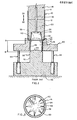
- the can doming die punch assembly 100 of the present invention is adapted for operating on a can body 110 of a type having an open top end 111, a cylindrical side wall 112, a generally flat bottom wall 114, and a relatively short length short radius annular shoulder 113 connecting the side wall and bottom wall.
- the can doming die punch assembly 100 in general, comprises a bodymaker punch 120 mounted as by a bolt 118 on a reciprocating ram unit 116 adapted to reciprocally move in a first horizontal direction 122 towards a domer die 180 and a second opposite horizontal direction 124 away from the domer die; a forming ring 140 adapted to formingly engage an inwardly positioned annular band portion 187 of the bottom wall 114 to provide a peripheral portion 203 of a dome 201 to be formed in the can bottom wall; and a fixed domer die 180 adapted to engage a central circular portion 189 of bottom wall 114 to form an inner dome portion 208 of the dome 201 to be formed in bottom wall 114; and biasing means such as air cylinders 194, 196 adapted to provide a constant relatively low biasing pressure in a direction 124 as the forming ring 140 moves in direction 122 during can dome formation.
- biasing means such as air cylinders 194, 196 adapted to provide a constant relatively low biasing pressure in a direction
- ram 116 and attached bodymaker punch 120 move can body 110 in direction 122 from an initial position in spaced relationship from forming ring 140 and domer die 180 as shown in Fig. 3.
- Can bottom wall 114 is initially engaged by annular surface 144 of forming ring 140.
- Ram 116 and bodymaker punch 120 subsequent to engagement of bottom wall 114 by surface 144 continue moving in direction 122 while forming ring 140 initially remains in a fixed position.
- the continued movement of the bodymaker punch and associated can 110 thus cause deformation of the can bottom 114 in the area engaged by the forming ring 140.
- Forming ring 140 remains relatively fixed until the bodymaker punch 120 and can body 110 have moved into the position illustrated in Fig.
- forming ring 140 comprises an annular can bottom engaging portion 142 having an outwardly facing generally outwardly convex can bottom engaging annular surface 144.
- the forming ring also comprises an internal cylindrical surface 146 adapted to slidingly accept the domer die 180 therewithin; and a recessed annular fluid discharge ring 148 adapted for collecting lubricating fluid and gases trapped between the can bottom 114 and various surfaces of the forming ring and domer die and having associated therewith axially extending fluid discharge passages 150, 152, etc. for expelling such collected fluids.
- the forming ring also comprised an outer body portion 154 having a cylindrical outer surface 156 and a pair of opposite radially extending surfaces 158, 160.
- the outwardly facing generally convex can bottom engaging annular surface 144 may include a generally planar radially extending surface portion 162 extending perpendicular to the direction of ram reciprocation and associated with an outer peripheral support ring portion 202 of the can bottom 200 being formed.
- Surface 144 also comprises an outwardly facing, concave, relatively short length, small radius (.05 in.), annular transition surface portion 164 which is associated with a can bottom transition surface 204 and which connects surface 162 to an outwardly facing, relatively large radius (.219 in.), convex surface portion 166 which is- associated with a peripheral portion 203 of the can dome 201 to be formed.
- Surface 166 is integrally connected to axially extending cylindrical surface 146 by radially inwardly facing, small radius (.05 in.), convex shoulder portion 168.
- Domer die 180 which is positioned in axially aligned relationship with bodymaker punch 120 comprises a main cylindrical body portion 182, having a cylindrical side wall 184 having a diameter, e.g. 1.736 in., about 30% less than the can body diameter, e.g. 2.50 in. and a dome shaped terminal end surface 186 which may have a radius approximately equal to the can diameter, e.g. 2.50 in.
- Domer die 180 also comprises a base portion 188 having a radially extending surface 190 affixed to a support surface and opposite radially extending surface 192 connected by a outer cylindrical wall portion 195.
- Biasing means such as air cylinders 194, 196 may have barrel portions 191, 193 mounted in recessed portions of the radially extending base portion 188 and may have piston portions 197, 199 attached to outer radial portions of forming ring 140.
- the air cylinders 194, 196, etc. having central longitudinal axes CC, DD extending parallel to the central longitudinal axis AA of the bodymaker punch 120 and domer die 180.
- the biasing air cylinders 194, 196 may be replaced by conventional biasing springs or other biasing means.
- a surprising feature of the can doming die punch assembly 100 of the present invention is that the pressure exerted by the forming ring surface 144 against the can bottom during doming may be significantly less, approximately an order of magnitude less, than the pressure exerted by a conventional pressure ring 40 against an associated can bottom during dome formation by conventional prior art techniques.
- a force of approximately 50 lbs. on the can bottom wall is sufficient to prevent axial can shortening and flower dome formation when using a can doming die punch assembly 100 of the present invention; whereas a force of approximately 900 lbs. must be exerted by a conventional pressure ring 40 against a can bottom to prevent axial shortening and flower dome formation.
- the present invention is much less likely to damage a can bottom than prior art apparatus such as described in Fig. 1.
Landscapes
- Engineering & Computer Science (AREA)
- Mechanical Engineering (AREA)
- Containers Having Bodies Formed In One Piece (AREA)
- Shaping Metal By Deep-Drawing, Or The Like (AREA)
- Cultivation Receptacles Or Flower-Pots, Or Pots For Seedlings (AREA)
Applications Claiming Priority (2)
| Application Number | Priority Date | Filing Date | Title |
|---|---|---|---|
| US06/823,308 US4723433A (en) | 1986-01-28 | 1986-01-28 | Method and apparatus for doming can bottoms |
| US823308 | 1986-01-28 |
Publications (2)
| Publication Number | Publication Date |
|---|---|
| EP0237161A2 true EP0237161A2 (fr) | 1987-09-16 |
| EP0237161A3 EP0237161A3 (fr) | 1989-12-13 |
Family
ID=25238382
Family Applications (1)
| Application Number | Title | Priority Date | Filing Date |
|---|---|---|---|
| EP87300725A Ceased EP0237161A3 (fr) | 1986-01-28 | 1987-01-28 | Procédé et appareil pour le bombage des fonds de boítes |
Country Status (4)
| Country | Link |
|---|---|
| US (1) | US4723433A (fr) |
| EP (1) | EP0237161A3 (fr) |
| JP (1) | JPS62230439A (fr) |
| AU (1) | AU597931B2 (fr) |
Cited By (2)
| Publication number | Priority date | Publication date | Assignee | Title |
|---|---|---|---|---|
| WO2011049775A1 (fr) | 2009-10-21 | 2011-04-28 | Stolle Machinery Company, Llc | Récipient et cuvette formée sélectivement, outillage et procédé correspondant pour les réaliser. |
| US10525519B2 (en) | 2009-10-21 | 2020-01-07 | Stolle Machinery Company, Llc | Container, and selectively formed cup, tooling and associated method for providing same |
Families Citing this family (12)
| Publication number | Priority date | Publication date | Assignee | Title |
|---|---|---|---|---|
| JP2508780B2 (ja) * | 1988-01-08 | 1996-06-19 | 東洋製罐株式会社 | ツ−ピ−ス缶用缶胴及びその成形法 |
| JPH089077B2 (ja) * | 1989-06-01 | 1996-01-31 | 東洋製罐株式会社 | 1体成形缶の底部の成形方法 |
| US4989434A (en) * | 1989-08-09 | 1991-02-05 | Adolph Coors Company | Method and apparatus for doming can bottoms |
| US5272902A (en) * | 1990-09-06 | 1993-12-28 | Preferred Machining Corporation | Domer assembly for metal containers with nitrogen pressure source |
| US5394727A (en) * | 1993-08-18 | 1995-03-07 | Aluminum Company Of America | Method of forming a metal container body |
| US7124613B1 (en) | 2005-07-28 | 2006-10-24 | Stolle Machinery Company, Llc | Press and method of manufacturing a can end |
| PL2739412T3 (pl) * | 2011-08-01 | 2018-10-31 | Crown Packaging Technology, Inc. | Wytwarzanie puszek |
| US9975164B2 (en) | 2012-05-18 | 2018-05-22 | Stolle Machinery Company, Llc | Container, and selectively formed shell, and tooling and associated method for providing same |
| CN109937097B (zh) | 2016-10-06 | 2022-04-08 | 斯多里机械有限责任公司 | 容器和选择成形杯、提供其的工具和相关方法 |
| USD839935S1 (en) * | 2016-12-19 | 2019-02-05 | Stolle Machinery Company, Llc | Truncated dome cup |
| USD827685S1 (en) * | 2016-12-19 | 2018-09-04 | Stolle Machinery Company, Llc | Truncated dome cup |
| JP2023152358A (ja) * | 2022-04-04 | 2023-10-17 | 東洋製罐株式会社 | 金属製有底筒体 |
Family Cites Families (13)
| Publication number | Priority date | Publication date | Assignee | Title |
|---|---|---|---|---|
| US1270933A (en) * | 1917-03-20 | 1918-07-02 | Charles C Elsener | Combination blanking and forming die. |
| US3730383A (en) * | 1971-07-29 | 1973-05-01 | Aluminum Co Of America | Container body and a method of forming the same |
| US3760751A (en) * | 1971-10-29 | 1973-09-25 | Pittsburh Aluminum | Container body and a method of forming the same |
| US3771345A (en) * | 1972-06-08 | 1973-11-13 | Standun | End forming station for metallic can body formers and the like |
| PL85400B1 (fr) * | 1973-10-30 | 1976-04-30 | Raciborska Fabryka Kotlow Rafakopo | |
| JPS588924B2 (ja) * | 1974-03-22 | 1983-02-18 | ヨシザキ コウゾウ | イツタイカンセイケイゴ ノ カタヌキオヨウイニスル ホウホウ |
| US4151927A (en) * | 1974-07-12 | 1979-05-01 | Reynolds Metals Company | Container construction |
| US3998174A (en) * | 1975-08-07 | 1976-12-21 | National Steel Corporation | Light-weight, high-strength, drawn and ironed, flat rolled steel container body method of manufacture |
| US4120419A (en) * | 1976-02-23 | 1978-10-17 | National Steel Corporation | High strength seamless chime can body, sheet metal container for vacuum packs, and manufacture |
| US4222494A (en) * | 1977-03-04 | 1980-09-16 | Reynolds Metals Company | Container |
| US4289014A (en) * | 1979-10-11 | 1981-09-15 | National Can Corporation | Double action domer assembly |
| US4372143A (en) * | 1980-10-10 | 1983-02-08 | Jos. Schlitz Brewing Company | Apparatus for forming a domed bottom in a can body |
| EP0196327A4 (fr) * | 1984-10-03 | 1988-06-27 | Nat Can Corp | Ensemble en dome pour la formation d'une paroi extreme d'un conteneur. |
-
1986
- 1986-01-28 US US06/823,308 patent/US4723433A/en not_active Expired - Fee Related
-
1987
- 1987-01-28 AU AU68069/87A patent/AU597931B2/en not_active Ceased
- 1987-01-28 EP EP87300725A patent/EP0237161A3/fr not_active Ceased
- 1987-01-28 JP JP62018144A patent/JPS62230439A/ja active Pending
Cited By (7)
| Publication number | Priority date | Publication date | Assignee | Title |
|---|---|---|---|---|
| WO2011049775A1 (fr) | 2009-10-21 | 2011-04-28 | Stolle Machinery Company, Llc | Récipient et cuvette formée sélectivement, outillage et procédé correspondant pour les réaliser. |
| EP2490836A4 (fr) * | 2009-10-21 | 2015-03-25 | Stolle Machinery Co Llc | Récipient et cuvette formée sélectivement, outillage et procédé correspondant pour les réaliser |
| US9481022B2 (en) | 2009-10-21 | 2016-11-01 | Stolle Machinery Company, Llc | Container, and selectively formed cup, tooling and associated method for providing same |
| US10525519B2 (en) | 2009-10-21 | 2020-01-07 | Stolle Machinery Company, Llc | Container, and selectively formed cup, tooling and associated method for providing same |
| EP3636361A1 (fr) * | 2009-10-21 | 2020-04-15 | Stolle Machinery Company, LLC | Récipient et cuvette formée sélectivement, outillage et procédé correspondant pour les réaliser |
| US20200147665A1 (en) | 2009-10-21 | 2020-05-14 | Stolle Machinery Company, Llc | Container, and selectively formed cup, tooling and assocaited method for providing same |
| US11826809B2 (en) | 2009-10-21 | 2023-11-28 | Stolle Machinery Company, Llc | Container, and selectively formed cup, tooling and associated method for providing same |
Also Published As
| Publication number | Publication date |
|---|---|
| US4723433A (en) | 1988-02-09 |
| AU6806987A (en) | 1987-07-30 |
| EP0237161A3 (fr) | 1989-12-13 |
| JPS62230439A (ja) | 1987-10-09 |
| AU597931B2 (en) | 1990-06-14 |
Similar Documents
| Publication | Publication Date | Title |
|---|---|---|
| US4790169A (en) | Apparatus for doming can bottoms | |
| JP3621129B2 (ja) | 金属容器本体を成形する方法 | |
| US4414836A (en) | Method of and apparatus for deep drawing metal containers | |
| US4723433A (en) | Method and apparatus for doming can bottoms | |
| US4587826A (en) | Container end panel forming method and apparatus | |
| US5605069A (en) | Beverage container with wavy transition wall geometry and method for producing the same | |
| US4808052A (en) | Method and apparatus for forming container end panels | |
| US5024077A (en) | Method for forming container with profiled bottom | |
| US4620434A (en) | Domer assembly for container-forming apparatus | |
| US4934168A (en) | Die assembly for and method of forming metal end unit | |
| US5150602A (en) | Crimping method for electrochemical cells | |
| US5857374A (en) | Method and apparatus for forming a can shell | |
| JPS60193834A (ja) | 罐の端部の強化成形方法及び装置 | |
| JPH0380570B2 (fr) | ||
| JP2013518723A (ja) | 缶製造 | |
| JP2002528274A (ja) | ビード付き缶端を形成するための方法及び装置 | |
| EP1743719A2 (fr) | Presse de couvercle et méthode de production d'une couvercle | |
| US4179909A (en) | Domer assembly for ironing machine | |
| US5970775A (en) | Method and apparatus for forming cup-shaped container bodies | |
| GB2131334A (en) | Tapered two-piece metal containers | |
| US5918499A (en) | Rivet formation | |
| EP0017434A1 (fr) | Réceptacles en forme de boîte et procédé et dispositif pour leur fabrication | |
| JPH04253533A (ja) | シームレス缶底部の形成方法 |
Legal Events
| Date | Code | Title | Description |
|---|---|---|---|
| PUAI | Public reference made under article 153(3) epc to a published international application that has entered the european phase |
Free format text: ORIGINAL CODE: 0009012 |
|
| AK | Designated contracting states |
Kind code of ref document: A2 Designated state(s): AT BE CH DE ES FR GB IT LI NL SE |
|
| 17P | Request for examination filed |
Effective date: 19871208 |
|
| PUAL | Search report despatched |
Free format text: ORIGINAL CODE: 0009013 |
|
| AK | Designated contracting states |
Kind code of ref document: A3 Designated state(s): AT BE CH DE ES FR GB IT LI NL SE |
|
| 17Q | First examination report despatched |
Effective date: 19910228 |
|
| STAA | Information on the status of an ep patent application or granted ep patent |
Free format text: STATUS: THE APPLICATION HAS BEEN REFUSED |
|
| 18R | Application refused |
Effective date: 19920424 |
|
| RIN1 | Information on inventor provided before grant (corrected) |
Inventor name: GRIMS, CONRAD MARTIN |