EP0237184A1 - Mémoire optique de fibre "in-line" - Google Patents
Mémoire optique de fibre "in-line" Download PDFInfo
- Publication number
- EP0237184A1 EP0237184A1 EP87301133A EP87301133A EP0237184A1 EP 0237184 A1 EP0237184 A1 EP 0237184A1 EP 87301133 A EP87301133 A EP 87301133A EP 87301133 A EP87301133 A EP 87301133A EP 0237184 A1 EP0237184 A1 EP 0237184A1
- Authority
- EP
- European Patent Office
- Prior art keywords
- pump
- loop
- pulse
- signal
- pulses
- Prior art date
- Legal status (The legal status is an assumption and is not a legal conclusion. Google has not performed a legal analysis and makes no representation as to the accuracy of the status listed.)
- Granted
Links
- 239000000835 fiber Substances 0.000 title claims abstract description 167
- 230000015654 memory Effects 0.000 title claims abstract description 29
- 230000003287 optical effect Effects 0.000 claims abstract description 88
- 230000004087 circulation Effects 0.000 claims abstract description 38
- 230000003134 recirculating effect Effects 0.000 claims abstract description 36
- 239000013307 optical fiber Substances 0.000 claims abstract description 26
- 238000000034 method Methods 0.000 claims abstract description 17
- 230000003321 amplification Effects 0.000 claims abstract description 14
- 238000003199 nucleic acid amplification method Methods 0.000 claims abstract description 14
- 230000008878 coupling Effects 0.000 claims description 124
- 238000010168 coupling process Methods 0.000 claims description 124
- 238000005859 coupling reaction Methods 0.000 claims description 124
- 230000000694 effects Effects 0.000 claims description 16
- 230000000737 periodic effect Effects 0.000 claims description 9
- 230000001902 propagating effect Effects 0.000 claims description 3
- 238000010079 rubber tapping Methods 0.000 claims description 2
- 238000001069 Raman spectroscopy Methods 0.000 abstract description 25
- 230000003993 interaction Effects 0.000 description 30
- 230000006870 function Effects 0.000 description 11
- 230000008569 process Effects 0.000 description 10
- 230000007423 decrease Effects 0.000 description 9
- 238000003780 insertion Methods 0.000 description 9
- 230000037431 insertion Effects 0.000 description 9
- 230000010287 polarization Effects 0.000 description 9
- 239000000463 material Substances 0.000 description 8
- VYPSYNLAJGMNEJ-UHFFFAOYSA-N Silicium dioxide Chemical compound O=[Si]=O VYPSYNLAJGMNEJ-UHFFFAOYSA-N 0.000 description 6
- 239000000382 optic material Substances 0.000 description 6
- 230000005540 biological transmission Effects 0.000 description 5
- 230000001419 dependent effect Effects 0.000 description 5
- 230000002829 reductive effect Effects 0.000 description 5
- 230000008901 benefit Effects 0.000 description 4
- 230000003247 decreasing effect Effects 0.000 description 4
- 239000005350 fused silica glass Substances 0.000 description 4
- 239000003921 oil Substances 0.000 description 4
- 230000009467 reduction Effects 0.000 description 4
- 230000003111 delayed effect Effects 0.000 description 3
- 239000003365 glass fiber Substances 0.000 description 3
- 230000009022 nonlinear effect Effects 0.000 description 3
- 238000005086 pumping Methods 0.000 description 3
- 238000000926 separation method Methods 0.000 description 3
- 230000015556 catabolic process Effects 0.000 description 2
- 238000005253 cladding Methods 0.000 description 2
- 230000001427 coherent effect Effects 0.000 description 2
- 238000006731 degradation reaction Methods 0.000 description 2
- 230000001934 delay Effects 0.000 description 2
- 230000005672 electromagnetic field Effects 0.000 description 2
- 230000000670 limiting effect Effects 0.000 description 2
- 239000000126 substance Substances 0.000 description 2
- 230000001360 synchronised effect Effects 0.000 description 2
- 230000007704 transition Effects 0.000 description 2
- 101100511184 Dictyostelium discoideum limB gene Proteins 0.000 description 1
- 230000009471 action Effects 0.000 description 1
- 230000002411 adverse Effects 0.000 description 1
- 238000004458 analytical method Methods 0.000 description 1
- 230000002238 attenuated effect Effects 0.000 description 1
- 239000004568 cement Substances 0.000 description 1
- 238000006243 chemical reaction Methods 0.000 description 1
- 229920006335 epoxy glue Polymers 0.000 description 1
- 238000001914 filtration Methods 0.000 description 1
- 230000007274 generation of a signal involved in cell-cell signaling Effects 0.000 description 1
- 239000011521 glass Substances 0.000 description 1
- 230000005283 ground state Effects 0.000 description 1
- 238000010438 heat treatment Methods 0.000 description 1
- 238000002329 infrared spectrum Methods 0.000 description 1
- 238000004519 manufacturing process Methods 0.000 description 1
- 230000010355 oscillation Effects 0.000 description 1
- 230000005610 quantum mechanics Effects 0.000 description 1
- 230000005855 radiation Effects 0.000 description 1
- 230000008929 regeneration Effects 0.000 description 1
- 238000011069 regeneration method Methods 0.000 description 1
- 229910052710 silicon Inorganic materials 0.000 description 1
- 239000010703 silicon Substances 0.000 description 1
- 230000002269 spontaneous effect Effects 0.000 description 1
Images


Classifications
-
- G—PHYSICS
- G02—OPTICS
- G02B—OPTICAL ELEMENTS, SYSTEMS OR APPARATUS
- G02B6/00—Light guides; Structural details of arrangements comprising light guides and other optical elements, e.g. couplings
-
- G—PHYSICS
- G02—OPTICS
- G02B—OPTICAL ELEMENTS, SYSTEMS OR APPARATUS
- G02B6/00—Light guides; Structural details of arrangements comprising light guides and other optical elements, e.g. couplings
- G02B6/24—Coupling light guides
-
- G—PHYSICS
- G02—OPTICS
- G02B—OPTICAL ELEMENTS, SYSTEMS OR APPARATUS
- G02B6/00—Light guides; Structural details of arrangements comprising light guides and other optical elements, e.g. couplings
- G02B6/24—Coupling light guides
- G02B6/26—Optical coupling means
- G02B6/28—Optical coupling means having data bus means, i.e. plural waveguides interconnected and providing an inherently bidirectional system by mixing and splitting signals
- G02B6/2804—Optical coupling means having data bus means, i.e. plural waveguides interconnected and providing an inherently bidirectional system by mixing and splitting signals forming multipart couplers without wavelength selective elements, e.g. "T" couplers, star couplers
- G02B6/2821—Optical coupling means having data bus means, i.e. plural waveguides interconnected and providing an inherently bidirectional system by mixing and splitting signals forming multipart couplers without wavelength selective elements, e.g. "T" couplers, star couplers using lateral coupling between contiguous fibres to split or combine optical signals
-
- G—PHYSICS
- G02—OPTICS
- G02B—OPTICAL ELEMENTS, SYSTEMS OR APPARATUS
- G02B6/00—Light guides; Structural details of arrangements comprising light guides and other optical elements, e.g. couplings
- G02B6/24—Coupling light guides
- G02B6/26—Optical coupling means
- G02B6/28—Optical coupling means having data bus means, i.e. plural waveguides interconnected and providing an inherently bidirectional system by mixing and splitting signals
- G02B6/2804—Optical coupling means having data bus means, i.e. plural waveguides interconnected and providing an inherently bidirectional system by mixing and splitting signals forming multipart couplers without wavelength selective elements, e.g. "T" couplers, star couplers
- G02B6/2861—Optical coupling means having data bus means, i.e. plural waveguides interconnected and providing an inherently bidirectional system by mixing and splitting signals forming multipart couplers without wavelength selective elements, e.g. "T" couplers, star couplers using fibre optic delay lines and optical elements associated with them, e.g. for use in signal processing, e.g. filtering
-
- G—PHYSICS
- G11—INFORMATION STORAGE
- G11C—STATIC STORES
- G11C21/00—Digital stores in which the information circulates continuously
-
- H—ELECTRICITY
- H01—ELECTRIC ELEMENTS
- H01S—DEVICES USING THE PROCESS OF LIGHT AMPLIFICATION BY STIMULATED EMISSION OF RADIATION [LASER] TO AMPLIFY OR GENERATE LIGHT; DEVICES USING STIMULATED EMISSION OF ELECTROMAGNETIC RADIATION IN WAVE RANGES OTHER THAN OPTICAL
- H01S3/00—Lasers, i.e. devices using stimulated emission of electromagnetic radiation in the infrared, visible or ultraviolet wave range
- H01S3/005—Optical devices external to the laser cavity, specially adapted for lasers, e.g. for homogenisation of the beam or for manipulating laser pulses, e.g. pulse shaping
- H01S3/0057—Temporal shaping, e.g. pulse compression, frequency chirping
-
- H—ELECTRICITY
- H01—ELECTRIC ELEMENTS
- H01S—DEVICES USING THE PROCESS OF LIGHT AMPLIFICATION BY STIMULATED EMISSION OF RADIATION [LASER] TO AMPLIFY OR GENERATE LIGHT; DEVICES USING STIMULATED EMISSION OF ELECTROMAGNETIC RADIATION IN WAVE RANGES OTHER THAN OPTICAL
- H01S3/00—Lasers, i.e. devices using stimulated emission of electromagnetic radiation in the infrared, visible or ultraviolet wave range
- H01S3/30—Lasers, i.e. devices using stimulated emission of electromagnetic radiation in the infrared, visible or ultraviolet wave range using scattering effects, e.g. stimulated Brillouin or Raman effects
- H01S3/302—Lasers, i.e. devices using stimulated emission of electromagnetic radiation in the infrared, visible or ultraviolet wave range using scattering effects, e.g. stimulated Brillouin or Raman effects in an optical fibre
-
- G—PHYSICS
- G02—OPTICS
- G02F—OPTICAL DEVICES OR ARRANGEMENTS FOR THE CONTROL OF LIGHT BY MODIFICATION OF THE OPTICAL PROPERTIES OF THE MEDIA OF THE ELEMENTS INVOLVED THEREIN; NON-LINEAR OPTICS; FREQUENCY-CHANGING OF LIGHT; OPTICAL LOGIC ELEMENTS; OPTICAL ANALOGUE/DIGITAL CONVERTERS
- G02F2203/00—Function characteristic
- G02F2203/54—Optical pulse train (comb) synthesizer
-
- H—ELECTRICITY
- H01—ELECTRIC ELEMENTS
- H01S—DEVICES USING THE PROCESS OF LIGHT AMPLIFICATION BY STIMULATED EMISSION OF RADIATION [LASER] TO AMPLIFY OR GENERATE LIGHT; DEVICES USING STIMULATED EMISSION OF ELECTROMAGNETIC RADIATION IN WAVE RANGES OTHER THAN OPTICAL
- H01S2301/00—Functional characteristics
- H01S2301/08—Generation of pulses with special temporal shape or frequency spectrum
-
- Y—GENERAL TAGGING OF NEW TECHNOLOGICAL DEVELOPMENTS; GENERAL TAGGING OF CROSS-SECTIONAL TECHNOLOGIES SPANNING OVER SEVERAL SECTIONS OF THE IPC; TECHNICAL SUBJECTS COVERED BY FORMER USPC CROSS-REFERENCE ART COLLECTIONS [XRACs] AND DIGESTS
- Y10—TECHNICAL SUBJECTS COVERED BY FORMER USPC
- Y10S—TECHNICAL SUBJECTS COVERED BY FORMER USPC CROSS-REFERENCE ART COLLECTIONS [XRACs] AND DIGESTS
- Y10S359/00—Optical: systems and elements
- Y10S359/90—Methods
Definitions
- the present invention relates generally to fiber optic optical memory devices, and particularly to in-line fiber optic memories which recirculate optical signals, and which utilize non-linear effects for amplification of the recirculating signals.
- Fiber optic recirculating memories typically comprise a loop of optical fiber and a fiber optic directional coupler for coupling light to and from the loop of optical fiber.
- An exemplary fiber optic recirculating memory is disclosed in U.S. Patent No. 4,473,270, issued September 25, 1984, which is incorporated by reference herein. As disclosed in that patent, a single signal pulse is supplied as an input to the memory device. This pulse recirculates in the loop and a portion of the pulse is coupled out of the loop on each circulation to provide a series of output signal pulses identical to the input signal pulse, although at smaller, gradually decreasing amplitudes.
- Such a device is particularly useful, for example, to provide a short term optical memory in a system where data is generated at a rate faster than it can be accepted by a data processor, or to adjust time delays between systems exchanging data (optical delay line) or to repeat data (data regeneration).
- This device may also be utilized as a pulse train generator, or as a filter.
- recirculating memory devices may be utilized as re-entrant fiber sensing loops for fiber optic gyroscopes.
- the recirculating memory disclosed in the above-referenced patent represents a significant advance in the art, and is quite advantageous for many optical memory applications, the optical memory capabilities of such devices are limited due to the fact that the circulating signal pulse is degraded by coupling a portion of this pulse on each circulation around the fiber loop to provide the train of output pulses. Further, fiber propagation losses attenuate the optical signal pulse as it propagates through the loop, causing additional losses. These losses cause the intensity of the signal pulse circulating in the loop to decay, which causes a concomitant decay in the series of output pulses, thereby limiting the number of useable output pulses and the lifetime of the optical signal memory.
- the present invention is an in-line fiber optic recirculating memory having a length of optical fiber, preferably splice-free, for receiving an optical signal pulse.
- the optical fiber forms a loop which is optically closed by means of an optical coupler, for example, a fiber optic directional coupler.
- the coupler couples the optical signal input pulse to the loop for circulation therein, and outputs a portion of the signal pulse on each circulation to provide a series of output pulses.
- the present invention further includes a light source for generating an input pump signal comprising a series of pulses.
- Each of these pulses is serially input to the loop by the coupler.
- the pulses circulate in the loop and generate Stokes light therein for amplification of the circulating optical signal pulse during each of plural circulations of the signal pulse.
- the optical wavelengths of the pump pulses and the optical signal pulse are selected such that the Stokes light has the same optical wavelength as the optical signal pulse.
- the coupling ratio of the coupler is greater than zero for the pump pulses so that each pump pulse makes plural circulations through the loop.
- the length of the loop provides a loop transit time for the pump pulses such that each pump pulse in a series of pump pulses makes plural circulations in the loop before overlapping with any subsequent pump pulse in the series of pump pulses. This allows the amplitude of the pump pulses to decay prior to overlapping, thereby reducing phase noise effects in the loop.
- the pump pulses are equally spaced and have the same time duration so that the pump signal is periodic.
- the period of the pump signal is less than the amount of the loop transit time.
- the time duration of each pump pulse is substantially less than the loop transit time.
- the period of the pump signal is substantially equal to an integer multiple of the time duration of each pump pulse.
- the sum of the period of the pump signal and the time duration of each pump signal pulse is substantially equal to the loop transit time.
- the invention further includes a method for generating a series of output pulses from a single input pulse.
- a loop having a loop length, is formed from a length of optical fiber that is closed by a coupler.
- An optical signal pulse having an optical signal wavelength is input into the optical fiber to circulate in the loop to provide a circulating optical pulse that makes plural circulations' in the loop.
- the circulating optical pulse propagates around the loop during a signal pulse loop propagation time which is determined by the optical signal wavelength and the loop length.
- a portion of the circulating signal pulse is tapped from the loop on each of the recirculations to provide the series of output pulses.
- a series of input pump pulses having an optical pump wave length are coupled into the fiber loop to cause stimulated scattering in the loop.
- the stimulated scattering generates Stokes light in the loop for amplification of the circulating signal pulse during each of the plural circulations by the signal pulses.
- the pump pulses propagate around the loop in a pump pulse loop propagation time determined by the optical pump wavelength and the loop length.
- Each input pump pulse has a pump pulse time duration.
- the optical signal wavelength and the optical pump wavelength are selected such that the Stokes light has the same optical wavelength as the optical signal wavelength.
- Each pump pulse is spaced apart in time from the next succeeding pump pulse in a series of pump pulses so that each pump pulse makes plural circulations in the loop before overlapping with any subsequent pump pulse. This allows the amplitude of the pump pulses to decay prior to any overlapping, thereby reducing phase noise effects in the loop.
- the pump pulses are spaced apart in time at a selected time delay so that the pump pulses are periodic.
- the time delay is selected so that the pump pulse has a period less than the pump pulse loop propagation time.
- the pump pulse time duration of each pump pulse is selected to be substantially less than the pump pulse loop propagation time.
- the period of the pump pulses is selected to be substantially equal to an integer multiple of the pump pulse time duration.
- the pump pulse time duration and the pump pulse period are selected so that the sum of the pump pulse period and the pump pulse time duration are substantially equal to the pump pulse loop propagation time.
- the pump signal has sufficient intensity to cause gain, for example, Raman gain caused by stimulated Raman scattering (SRS), in the core of the fiber.
- the optical fiber forming the loop is single mode fiber, which typically has a core diameter on the order of 5-10 microns.
- the small core diameter of single mode fiber is highly advantageous over the larger core diameter multimode fiber, since its small size provides increased optical power density in the fiber core for a given amount of pump light, and thus increases the optical gain.
- the pump source has a coherence length which is short compared to the length of the fiber loop to ensure that any of the pump light that recirculates in the loop does not cause a resonant effect.
- the pulse width of the signal pulse is preferably less than the loop length to ensure that the signal pulse does not interfere with itself while circulating in the loop.
- Stimulated Raman scattering may be viewed as a three level laser emission process in which molecules of the active media (i.e., the fiber core) are excited from the ground level to an excited virtual level by absorbing input pump photons. Return of the excited molecules to an intermediate level results in the emission of photons, commonly referred to as "Stokes photons". These Stokes photons have a frequency downshifted with respect to the pump frequency by a characteristic amount, typically referred to as the Raman shift. In the case of SRS in a fused silica fiber, the Stokes photons have a frequency which is about 13-15 terahertz (THz) below the frequency of the pump light. In addition to the emission of Stokes photons, the transition from the intermediate level back to the ground level results in the emission of phonons. However, such phonons are of little interest in the present invention, as they are quickly absorbed by the fiber and converted to heat.
- THz terahertz
- the input signal pulse has a wavelength which is equal to the Stokes wavelength.
- the signal pulse When the signal pulse is injected into the fiber loop, such pulse will stimulate relaxation of the excited molecules and emission of photons at the Stokes wavelength. These stimulated photons have the same phase characteristics and frequency as the input signal pulse, and thus, provide coherent amplification of the input signal pulse.
- the optical gain depends upon the gain coefficient of the fiber (g); the optical power Pp c of the input pump signal; the effective interaction area (A f ) of the optical fiber (i.e., the area of mode or electromagnetic field overlap between the signal pulse and the pump signal); and the effective interaction length (L f ) of the fiber loop (i.e., the calculated length, less than the loop length, which accounts for pump power attenuation along the fiber loop).
- the gain is also dependent upon the attenuation (a) of the fiber, the length (L) of the fiber loop, and the coupling ratio ( ⁇ ) of the coupler.
- the invention may be implemented utilizing either an ordinary "standard” coupler or a specifically adapted “multiplexing coupler".
- standard coupler refers to a coupler in which the coupling ratio for the input signal pulse is close to that of the pump signal, such that the coupling ratios differ by no more than 0.2.
- a “multiplexing coupler” is a coupler which exhibits a sizeable difference in coupling ratio for the pump signal and signal pulse, such that the difference in coupling ratios is greater than 0.2.
- the coupler is set to yield high gain, the loop losses will be high, while, if the coupler is set for low losses, the gain will be low. Accordingly, there exists an optimum set of coupling ratios corresponding to a specific coupler tuning which minimizes the pump power required for compensation of total round trip losses. It has been observed however that with such mode of operation (i.e., using a standard coupler with a relatively high pump coupling ratio) the recirculation and interference of pump power in the loop causes enhanced pump power fluctuations or noise which in turn cause gain fluctuations and thus sizeable signal intensity noise. These fluctuations are due to interference between the recirculating pump electromagnetic fields of short coherence time and are commonly referred to as a phase noise effect.
- a multiplexing coupler may be utilized, rather than a standard coupler.
- the mutliplexing coupler is formed to have a large interaction length.
- a tuning position for the coupler for which the interaction length is substantially equal to an even number of coupling lengths for the pump signal and substantially an odd number of coupling lengths for the signal pulse so that the coupling ratio for the pump signal is zero, or close to zero, while the coupling ratio for the signal pulse is close to unity, but not exactly unity.
- a coupling ratio of zero for the pump signal makes it possible to utilize the entire amount of input pump power and thereby provides for maximum possible gain, while a coupling ratio close to unity (but not exactly unity) for the signal pulse provides for minimum round trip loop loss.
- the invention may be implemented in either a forward configuration in which the pump signal and signal pulse are both input into the same end of the fiber loop such that the signal pulse propagates in the same direction around the loop as the pump signal, or it may be implemented in a backward configuration in which the pump signal and signal pulse are input into opposite ends of the loop, so that the signal pulse propagates in a direction opposite that of the pump signal.
- a backward configuration is utilized, since it has been found that this advantageously averages out the effect of pump fluctuation frequencies (i.e., those larger than the reciprocal of the loop transit time) on the signal amplitude fluctuations.
- the present invention suppresses the effects of phase noise, and thus, minimizes the signal intensity noise while using a coupler having a pump coupling ratio substantially greater than zero, such that the pump power is recirculated in the loop.
- the pump signal is input to the recirculating loop as a series or train of pump pulses having a selectable pulse width and a selectable delay between the beginning of each successive input pump pulse.
- the pulse width and delay are selected so that each input pump pulse makes plural circulations in the fiber loop before overlapping with any subsequent pump pulse in the series of pump pulses. This allows the amplitude of the recirculating pump pulses to decay before overlapping occurs and thus reduces the effect of their mutual interference.
- the pump power recirculating in the loop is thereby stabilized causing a sizeable reduction of gain noise, which in turn effects a drastic reduction of the amplified signal noise. Therefore, the invention improves the output signal stability when using a non-zero pump coupling ratio, such as exists in the above discussed standard coupler.
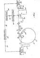
- the optical memory of one embodiment of the present invention comprises a continuous, uninterrupted strand 10 of optical fiber, preferably single-mode optical fiber, having an input end portion 12, a loop portion 14, and an output end portion 16.
- the single-mode fiber 10 is optically coupled together by means of a fiber optic, evanescent field, four port, directional coupler 20, having ports 1 and 2 on one side thereof, and ports 3 and 4 on the other side thereof. Tracing the fiber 12 from one end to the other, the fiber 10 first passes through ports 1 and 3, and then through ports 2 and 4, so that the loop 14 extends from ports 3 and 2, while the input portion 12 extends from port 1, and the output portion 16 extends from port 4.
- a signal pulse generator 22 is provided to selectively introduce an input pulse 21 into the input fiber portion 12.
- the coupler 20 couples a portion 24 of this pulse 21 to the loop 14 for recirculation therein.
- Each time the pulse 24 circulates in the loop a portion is output ' through the output fiber portion 16 to provide a series or train of output pulses 26.
- These output pulses 26 are directed through a lens 27 to a beam splitter 29 which splits the output pulses 26 and directs a portion through a monochromator 28 to suppress Fresnel reflections and scattered pump light, so as to filter the output signal pulses 26.
- the output signal pulses 26 may be directed to a detector 30 which converts the optical signals to electrical signals for display on an oscilloscope 32.
- a spike filter at the wavelength of the optical signal pulses 26 or a dispensive element such as a prism or grating
- the embodiment of Figure 1 also includes a pump source 34 for producing a pump light signal 31.
- the signal 31 is a pulse having a width which is at least as long as the desired length of the output pulse train 26.
- the pump pulse 31 should have a duration which is at least as long as the desired.number of output pulses times the loop transit time.
- the duration of the pulse 31 is selected to be at least 50 times the loop transit time so as to yield at least 50 substantially identical output pulses 26.
- the pump source 34 of the embodiment of Figure 1 comprises a continuous wave Nd:YAG laser having a CW power of 2 watts and a wavelength of 1.064 microns.
- a chopper 35 is included at the output of the pump source 34 to chop the pump signal into relatively long pulses (e.g., 0.5 msec).
- a chopper typically comprises a rotating disk having apertures to alternately block and pass the output light of a laser at a specific frequency.
- an acousto-optic or electro-optic modulator may be used instead of the chopper 35.
- the pump signal 31 is directed from the pump source 34 to the beam splitter 29, where the light is split such that one portion (not shown) is directed to the monochromator 28, and the other portion 33 is directed to the lens 27 for introduction into the output end portion 16 of the fiber 10 for propagation through the loop 14.
- the signal portion 33 in the end portion 16 will be referred to as the "input pump signal.”
- the filter characteristics of the monochromator 28 are selected so that the portion of the pump signal directed towards the monochromator 28 will be blocked to prevent it from reaching the detector 30.
- the pump source 34 and signal pulse generator 22 are connected by respective lines 36, 38 to a synchronizer 40.
- the synchronizer 40 synchronizes the chopped pump signal pulses to the signal pulses from the pulse generator 22, such that the pump light enters the loop 14 just prior to the signal pulses so that the pump light is present in the loop when the signal pulses arrive.
- the coherence length of the pump source 34 is relatively short compared to the length of the fiber loop 14 to ensure that any of the pump light that recirculates in the loop 14 does not interfere with itself.
- the width of the signal pulse 21 produced by the generator 22 should preferably be less than the length of the fiber loop to ensure that the circulating pulse 24 does not interfere with itself as it circulates through the loop 14.
- the wavelength and amplitude of the input pump signal 33 are selected to cause stimulated scattering in the fiber loop 14 at the pulse signal wavelength.
- stimulated scattering produces photons at a wavelength referred herein as the "Stokes wavelength".
- the Stokes wavelength is 1.12 microns for a pump wavelength of 1.064 microns.
- the photons produced by this stimulated scattering amplify the circulating pulse 24 as it propagates around the fiber loop 14. However, for such amplification to occur, it is important that the signal pulse 21 (and the circulating pulse 24) be at a wavelength equal to the Stokes wavelength.
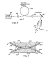
- the signal pulse generator 22 comprises a laser 42 which produces light at a wavelength identical to that of the pump source 34 (e.g., 1.064 microns), and a signal generating loop 44, formed of the same type of fiber as the loop 14, as shown in Figure 2.
- the laser 42 may be a Q-switched Nd:YAG laser having an output wavelength of 1.064 microns, a peak power of 120 watts and a switching rate of 50 Hz, so as to generate relatively thin (500 nsec) high power pump pulses which are widely spaced (e.g., a spacing greater than the pump signal duration).
- the loop 44 may have a length of about 1 km.
- the light from the source 42 is input to one end of the loop 44 through a lens 45 to generate stimulated scattering in the loop 44 such that a wave having the Stokes wavelength of e.g. 1.12 microns is output, together with the pump light, at the other end of the fiber.
- the Stokes wave and the pump light are then directed through a lens 46 to a diffraction grating 48 which separates the two wavelengths into two diverging rays.
- a diaphragm 49 with a slit therein is positioned to block the 1.064 micron pump light, but pass the 1.12 micron Stokes light to provide the signal pulse 21 (Figure 1) which is input to the input end portion 12 of the fiber 10 ( Figure 1) through a lens 41.
- the signal pulse generator 22 provides signals at exactly the same optical wavelength as the Stokes light generated in the fiber loop 14 ( Figure 1).
- FIG. 3 A preferred fiber optic directional coupler for use as the coupler 20 (Figure 1) in the optical memory of the present invention is shown in Figure 3.
- this coupler includes two exemplary strands 50A and 50B of a single mode fiber optic material mounted in longitudinal arcuate grooves 52A and 52B, respectively, formed in optically flat, confronting surfaces of rectangular bases or blocks 53A and 53B, respectively.
- the block 53A with the strand 50A mounted in the groove 52A will be referred to as the coupler half 51A
- the block 53B with the strand 50B mounted in the groove 52B will be referred to as the coupler half 51B.
- the arcuate grooves 52A and 52B have a radius of curvature which is large compared to the diameter of the fibers 50, and have a width slightly larger than the fiber diameter to permit the fibers 50, when mounted therein, to conform to a path defined by the bottom walls of the grooves 52.
- the depth of the grooves 52A and 52B varies from a minimum at the center of the blocks 53A and 53B, respectively, to a maximum at the edges of the blocks 53A and 53B, respectively.
- the grooves 52 are rectangular in cross-section, however, it will be understood that other suitable cross-sectional contours which will accommodate the fibers 50 may be used alternatively, such as U-shaped cross-section or a V-shaped cross-section.
- the depth of the grooves 52 which mount the strands 50 is less than the diameter of the strands 50, while at the edges of the blocks 53, the depth of the grooves 52 is preferably at least as great as the diameter of the strands 50.
- Fiber optic material was removed from each of the strands 50A and 50B, e.g., by lapping, to form respective oval-shaped planar surfaces, which are coplanar with the confronting surfaces of the blocks 53A, 53B. These oval surfaces, where the fiber optic material removed, will be referred to herein as the fiber "facing surfaces".
- the amount of fiber optic material that has been removed increases gradually from zero towards the edges of the blocks 53 to a maximum towards the center of the blocks 53. This tapered removal of the fiber optic material enables the fibers to converge and diverge gradually, which is advantageous for avoiding backward reflection and excess loss of light energy.
- the coupler halves 51A and 51B are identical, and are assembled by placing the confronting surfaces of the blocks 53A and 53B together, so that the facing surfaces of the strands 50A and 50B are juxtaposed in facing relationship.
- An index matching substance (not shown), such as index matching oil, is provided between the confronting surfaces of the blocks 53.
- This substance has a refractive index approximately equal to the refractive index of the fiber cladding, and also functions to prevent the optically flat surfaces from becoming permanently locked together.
- the oil is introduced between the blocks 53 by capillary action.
- An interaction region 54 is formed at the junction of the strands 50, in which light is transferred between the strands by evanescent field coupling. It has been found that, to ensure proper evanescent field coupling, the amount of material removed from the fibers 50 must be carefully controlled so that the spacing between the core portions of the strands 50 is within a predetermined "critical zone".
- the evanescent fields extend into the cladding and decrease rapidly with distance outside their respective cores. Thus, sufficient material should be removed to permit each core to be positioned substantially within the evanescent field of the other. If too little material is removed, the cores will not be sufficiently close to permit the evanescent fields to cause the desired interaction of the guided modes, and thus, insufficient coupling will result.
- each strand receives a significant portion of the evanescent field energy from the other strand, and good coupling is achieved without significant energy loss.
- the critical zone includes that area in which the evanescent fields of the fibers 50A and 50B overlap with sufficient strength to provide coupling, i.e., each core is within the evanescent field of the other.
- mode perturbation occurs when the cores are brought too close together.
- the critical zone is defined as that area in which the evanescent fields overlap with sufficient strength to cause coupling without substantial mode perturbation induced power loss.
- the critical zone for a particular coupler is dependent upon a number of interrelated factors such as the parameters of the fiber itself and the geometry of the coupler. Further, for a single mode fiber having a step-index profile, the critical zone can be quite narrow. In a single mode fiber coupler of the type shown, the required center-to-center spacing between the strands 50 at the center of the coupler is typically less than a few (e.g., 2-3) core diameters.
- the strands 50A and 50B (1) are identical to each other; (2) have the same radius of curvature at the interaction region 54; and (3) have an equal amount of fiber optic material removed therefrom to form their respective facing surfaces.
- the fibers 50 are symmetrical, through the interaction region 54, in the plane of their facing surfaces, so that their facing surfaces are coextensive if superimposed. This ensures that the two fibers 50A and 50B will have the same propagation characteristics at the interaction region 54, and thereby avoids coupling attenuation associated with dissimilar propagation characteristics.
- the blocks or bases 53 may be fabricated of any suitable rigid material.
- the bases 53 comprise generally rectangular blocks of fused quartz glass approximately 1 inch long, 1 inch wide, and 0.4 inch thick.
- the fiber optic strands 50 are secured in the slots 52 by suitable cement, such as epoxy glue.
- suitable cement such as epoxy glue.
- One advantage of the fused quartz blocks 53 is that they have a coefficient of thermal expansion similar to that of glass fibers, and this advantage is particularly important if the blocks 53 and fibers 50 are subjected to any heat treatment during the manufacturing process.
- Another suitable material for the block 53 is silicon, which also has excellent thermal properties for this application.
- the coupler of Figure 3 includes four ports, labeled A, B, C, and D, which correspond to the ports 1, 2, 3, and 4, respectively, of the coupler 20 in Figure 1.
- ports A and B which correspond to strands 50A and 50B, respectively, are on the left-hand side of the coupler, while the ports C and D, which correspond to the strands 50A and 50B, respectively, are on the right-hand side of the coupler.
- input light is applied to port A. This light passes through the coupler and is output at port C and/or port D, depending upon the amount of power that is coupled between the strands 50.
- the term “coupling ratio” is defined as the ratio of the coupled power to the total output power.
- the coupling ratio would be equal to the ratio of the power at port D to the sum of the power output at ports C and D.
- This ratio is also referred to as the "coupling efficiency", and when so used, is typically expressed as a percent.
- the term “coupling ratio” it should be understood that the corresponding coupling efficiency is equal to the coupling ratio times 100.
- a coupling ratio of 0.5 is equivalent to a coupling efficiency of 50%.
- the coupler may be "tuned” to adjust the coupling ratio to any desired value between zero and 1.0, by offsetting the facing surfaces of the blocks 53. Such tuning may be accomplished by sliding the blocks 53 laterally relative to each other, so as to increase the distance between the fiber cores.
- the coupler is highly directional, with substantially all of the power applied at one side of the coupler being delivered to the other side of the coupler. That is, substantially all of the light applied to input port A is delivered to the ports C and D, without contra-directional coupling to port B. Likewise, substantially all of the light applied to port B is delivered to the ports C and D. Further, this directivity is symmetrical, so that substantially all of the light applied to either port C or input port D is delivered to the ports A and B. Moreover, the coupler is essentially non-discriminatory with respect to polarizations, and thus, preserves the polarization of the light. Thus, for example, if a light beam having a vertical polarization is input to port A, the light crosscoupled from port A to_ port D, as well as the light passing straight through from port A to port C, will remain vertically polarized.
- the coupler is also a low loss device, having insertion or throughput losses typically on the order of 2-3 percent.
- insertion loss refers to the real scattering losses of light passing through the coupler, from one side to the other. For example, if light is applied to port A, and 97% of that light reaches ports C and D (combined), the insertion loss would be 0.03 (3%).
- the term "coupler transmission” is defined as one minus the insertion loss. Thus, if the insertion loss is 0.03 (3%), the coupler transmission is 0.97 (97%).
- the coupler depicted in Figure 3 exhibits wavelength dependencies such that its coupling ratio may be different for two signals having a large wavelength separation.
- the coupling ratios for the coupler of Figure 3 are ordinarily close to each other (i.e., within 0.2).
- the coupler of Figure 3 may, nevertheless, be specially adapted to operate as a "multiplexing coupler", such that the coupler exhibits significantly different coupling ratios for different wavelengths, even if the wavelength separation is quite small.
- the coupler can be made to provide virtually any desired coupling ratio for substantially any pair of wavelengths.
- the coupler 20 operates on evanescent field coupling principles in which guided modes of the strands 50 interact through their evanescent fields to cause light to be transferred between the strands 50 at the interaction region 54.
- the amount of light transferred is dependent upon the proximity and orientation of the cores as well as the effective length of the interaction region 54.
- the length of the interaction region 54 is dependent upon the radius of curvature of the fibers 50, and, to a limited extent, the core spacing, although it has been found that the effective length of the interaction region is substantially independent of core spacing.
- the "coupling length” i.e., the length within the interaction region 54 which is required for a single, complete transfer of a light signal from one fiber to the other
- the coupling length is a function of core spacing, as well as wavelength.
- the light will transfer back to the strand from which it originated.
- the effective interaction length becomes a greater multiple of the coupling length, and the light transfers back to the other strand.
- the light may make multiple transfers back and forth between the two strands as it travels through the region 54, the number of such transfers being dependent on the length of the interaction region 54, the light wavelength, and the core spacing.
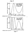
- Figure 4 provides a plot of coupled power versus signal wavelength in the visible and near infrared spectrum for a particular coupler geometry.
- the effective interaction length of the coupler is an odd multiple of the coupling length for the wavelength 720 nm, but an even multiple of the coupling length for the wavelength 550 nm.
- the wavelength 720 nm will be 100X coupled, while the wavelength 550 nm will be effectively uncoupled, yielding a wavelength resolution of 170 nm.
- Other wavelengths exhibit different coupling efficiencies. For example, 590 nm has a coupling efficiency of about 5-10% and 650 nm has a coupling efficiency of about 80-85%.
- the coupler may be tuned to precisely adjust the coupling length for the wavelengths to yield the desired coupling efficiencies. This is accomplished by offsetting the fibers by sliding the blocks 53A, 53B ( Figure 3) relative to each other in a direction normal to the axis of the fibers 50A, SOB. Such an offset has the effect of increasing the core spacing. If the required offset is small, it will not upset the resolution.
- Figure 6 provides a plot of relative coupled power versus wavelength for three increasing values of fiber offset (0 microns, 0.5 microns, and 1.0 microns). The curve is seen to shift toward increasing wavelengths as the offset increases, while the period of oscillation (or resolution) remains virtually unchanged. In this particular example in which the radius of curvature was 200 cm and the minimum core-to-core spacing was 4 microns, a one micron offset shifted the curve by approximately 45 nm.
- the embodiment of Figure 1 of the present invention can utilize the above-described multiplexing coupler and can also utilize a standard nonmultiplexing coupler. If a multiplexing coupler is utilized, the coupler is preferably adapted to exhibit overcoupling for either the pump wavelength (e.g., 1.064 microns) or the signal pulse wavelength (e.g., 1.12 microns), so as to provide a very low coupling ratio for the pump signal 33 and a very high coupling ratio for the signal pulse 21. Except for the type of coupler used, both embodiments of Figure 1 are the same.
- the pump wavelength e.g., 1.064 microns
- the signal pulse wavelength e.g., 1.12 microns
- Figure 7 shows the fiber 10 and coupler 20 of Figure 1 without the associated components, for clarity of illustration.
- the device of Figure 7 will first be described in terms of operation without the pump source 34 ( Figure 1).
- the input signal pulse 21 propagates along the input fiber portion 12 to port 1 of the coupler, where this pulse is split by the coupler into the circulating pulse 24, which exits the coupler through port 3, and a pulse (not shown) which exits the coupler, 20 through port 4.
- the portion of the pulse 24 exiting port 4 can be substantial. Accordingly, it would be preferable to utilize a switchable coupler as the coupler 20, if available, so that the signal pulse coupling ratio can be switched to a lower value when the signal pulse 21 is initially coupled to the loop 14, and switched back to a high value before the circulating signal 24 completes its first circulation. It should be recognized, however, that the device will function in the intended manner regardless of whether the coupler 20 is switchable.
- the pulse 24 After the pulse 24 exits port 3 of the coupler, it circulates through the loop 14 and arrives at port 2 of the coupler, where a portion of the pulse 24 is coupled to port 3, to again circulate in the loop 14, while another portion is output from port 4 as the pulse 26a.
- the coupling ratio of the coupler 20 for the circulating signal 24 is 0.9, and for simplicity, it will be assumed that the loop 14 and coupler 20 are lossless. If it is further assumed that the pulse 24 has a normalized value of 1.0 on its first circulation about the loop 14, it follows that 10% of the pulse 24 will exit port 4 of the coupler, yielding a normalized value of 0.1 for the first output pulse 26a.
- the remaining 90% of the light will be coupled to port 3 for propagation about the loop a second time, thus yielding a normalized value of 0.9 for the pulse 24 on its second circulation.
- 10% of the light will again exit port 4 of the coupler to form the second pulse 24b, which is delayed from the pulse 26a by an amount equal to the round-trip transit time of the fiber loop 14.
- the amplitude of the pulse 26b will be 10% of the 0.9 normalized value of the second recirculating pulse, or 0.09.
- the pulse 24 will have a normalized value of 0.81 (90% x 0.9).
- 10% of the 0.81 normalized amplitude of the pulse 24 will be coupled to form a third output pulse 26c, which is separated from the second output pulse 26b by the round-trip transit time of the loop, and has a normalized value of 0.081.
- the normalized amplitude values of subsequent pulses may be found.
- the fourth pulse 26d will have a normalized amplitude of .073
- the fifth pulse 26e will have a normalized amplitude of .066. Accordingly, it can be seen that each time the pulse 24 circulates in the loop 14, an output pulse is generated such that a train of output pulses 26 is provided at the fiber output end portion 16.
- the present invention advantageously amplifies the pulse 24 on each circulation through the loop 14 to compensate for round-trip losses such that the pulse 24 has a normalized value of 1.0 each time it arrives back at port 2 of the coupler, thereby providing an output pulse train 26-1 to 26-5 having a constant amplitude. This is accomplished without splicing any discrete amplifying components into the loop 14, but rather by utilizing the core of the fiber 14 as the active amplifying medium.
- the pump source 34 ( Figure 1) inputs the pump signal 33 into the output end portion 16 of the fiber 10 for introduction into the loop 14 through the coupler 20.
- the coupler 20 splits the pump signal in an amount depending on the coupling ratio such that a portion outputs the coupler through port 1 and another portion outputs the coupler through port 2 for propagation through the loop 14.
- the coupling ratio for the pump signal 33 is the same as that previously assumed for the signal pulse 21, namely 0.9, it follows that 90% of the light will exit port 1 and be lost, while the remaining 10% will be available to propagate through the fiber loop and pump the fiber loop 14.
- the portion of the pump signal which propagates in the fiber loop 14 is depicted in Figure 7 as the arrow labelled "loop pump signal".
- the loop pump signal propagates in a direction opposite that of the circulating pulse 24.
- the pump signal duration for this embodiment is at least equal to the number (N) of desired constant amplitude output pulses (e.g., 26-1 through 26-N) times the round-trip transit time of the loop.
- the input pump signal pulse 33 has a sufficiently long duration such that it can be considered as a continuous wave for the desired number of circulations of the circulating pulse 24.
- the loop 14 is thus continuously activated by pump light throughout the duration of the constant amplitude pulse train output 26-1, 26-2 ... 26-N.
- the optical power of the pump signal 33 is selected to provide sufficient optical power for the portion of this signal 33 propagating in the fiber loop 14 to cause stimulated scattering. As discussed above, such stimulated scattering will generate photons at the Stokes wavelength, so as to amplify the circulating signal pulse 24 as it propagates through the loop 14.
- stimulated Raman scattering is a phenomena in which coherent radiation is generated by optically pumping the molecules of a material, such as an optical fiber, into an excited vibrational state.
- the process may be viewed as a three- level laser emission process in which molecules of the active media are excited from the ground level to an excited virtual level by absorbing input pump photons. Return of the excited molecules to an intermediate level results in the emission of photons, commonly referred to as "Stokes photons" which have a characteristic wavelength, commonly referred to as the "Stokes wavelength”.
- the Stokes photons have a particular optical frequency relationship to the pump light which depends upon the molecular structure of the core of the optical fiber.
- this frequency relationship causes the Stokes photons to be shifted in frequency relative to the pump signal by an amount, referred herein as the "Stokes shift", which, for SRS, is typically about 13 to 15 THz.
- the Stokes shift in SRS is due to the difference in energy between the incident pump photon and the vibrational level of the molecule. It should be noted that the transition of the excited molecules from the intermediate level back to the ground level results in emission of phonons, although such phonons are of little interest in the present invention, as they are quickly absorbed by the fiber and converted to heat.
- the input signal light 21, 24 has a wavelength which is equal to the Stokes wavelength.
- the circulating signal pulse 24 When the circulating signal pulse 24 is injected into the loop 14, such pulse 24 will stimulate relaxation of the excited molecules and emission of photons at the Stokes wavelength.
- the stimulated photons have the same phase characteristics and frequency as the pulse 24, and thus, amplify the circulating pulse 24.
- one of the Stokes background waves travels around the loop in the same direction as the pump signal (referred herein as the "forward” Stokes background wave), while the other travels in the opposite direction around the loop relative to the pump signal (referred herein as the "backward” Stokes background wave).
- the output 26 of the optical memory will be comprised of a superposition of light from the amplified signal pulse 24 and light from the backward Stokes background wave.
- the backward Stokes background wave may be considered as background noise in the optical memory output 26.
- the forward Stokes background wave has no significant effect on the output 26, since it propagates in a direction opposite to the circulating signal 24.
- these Stokes background waves may grow rapidly in amplitude, due to the fact that they will be amplified in the same manner as the circulating pulse 24, thereby increasing the noise level and adversely affecting the signal to noise ratio.
- the growth of the background Stokes wave can be maintained at a level, such that the background Stokes power is several orders of magnitude below that of the circulating signal 24 for a large number of circulations (e.g. thousands).
- the optical power of the input pump signal 33 should be selected to provide sufficient pump power in the fiber loop 14 such that the stimulated scattering process yields just enough amplification (e.g., Raman gain) to compensate for the total round-trip loop losses of the circulating pulse 24.
- a portion of these round-trip loop losses is due to fiber attenuation which causes propagation losses in the optical fiber loop 14. These propagation losses cause some degradation of the pulse 24 as it propagates around the loop 14.
- the attenuation (a) of an optical fiber is typically expressed in dB per kilometer.
- the total propagation losses per circulation (in dB) due to fiber attenuation are equal to aL, where L is length of the fiber loop 14 in kilometers.
- Equation 1 thus indicates the fraction of the optical power of the pulse 24 which is lost on each circulation through the loop 14.
- the fraction of optical power remaining in the loop 14 will be referred to as the loop transmission (T loo p), and is given by: where T s is the fiber transmission for the signal pulse 24 (i.e., exp(- ⁇ s L)).
- the gain (G) should equal the total loop loss (6), such that:
- Equation 6 is a transcendental equation, and thus, the coupling coefficient cannot be expressed directly as a function of the pump power (Pp c ).
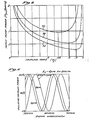
- the pump power Pp c defined by Equation (6) may be plotted as a function of the coupling ratio, as shown in the curves of Figure 8.
- the curves of Figure 8 illustrate the coupling ratio as a function of the input pump power, P pc (in watts) necessary to achieve an optical gain which will compensate for total loop losses, for various values of fiber attenuation (a) assuming, in accordance with Equation 6, that the coupler 20 exhibits substantially the same coupling ratios for the pump light and the signal light. It was also assumed that the loop length (L) was 810 meters.
- the optical input pump power (Pp c ) required for loop loss compensation varies dramatically with the coupling ratio ( ⁇ ). Indeed, the required pump power (Pp c ) increases toward infinite values for very low coupling ratios and for very high coupling ratios. For intermediate coupling ratios, the required pump power Pp c decreases dramatically.
- the curve 70 corresponds to a fiber attenuation of 1.8 dB per kilometer
- the curve 72 and 74 correspond to attenuations of 1.0 dB per kilometer and 0.5 dB per kilometer, respectively. It may be seen that, in general, the required pump power Pp c decreases as the fiber attenuation decreases. Further, there is an optimum coupling ratio for each of the curves 70, 72, 74, corresponding to the point of zero slope, at which the required pump power Pp c is a minimum.
- the pump power utilized be no more than about 2 watts. It has been found, for example, that pump powers in excess of,2 watts tend to cause "burn out" of the coupler 20, in that the index matching oil between the blocks 53 tends to burn, thereby damaging the coupler. Although such coupler "burn out” might be alleviated by fusing the fiber together without oil therebetween, high optical powers are disadvantageous for other reasons. For example, they may cause undesirable non-linear effects (e.g., multi-Stokes effect) in the fiber 10. Further, high power laser instability may cause enhanced amplitude variations in the output pulse train 26, as opposed to lower power lasers. Moreover, such amplitude instability of high power lasers tend to cause the circulating Stokes background waves to build up very rapidly in the fiber loop. This buildup of the Stokes background can significantly reduce the signal to noise ratio of the output pulses and/or cause coupler burn out.
- the coupling ratio of the coupler 20 should be selected such that the input pump signal 33 optical power Pp c required for loop loss compensation,is no greater than about 2 watts.
- This relationship may be defined by rewriting Equation 6 as:
- Equations 6 and 7 assume that the coupling ratios for the pump light and the signal light are the same. Thus, these equations are accurate to a good approximation only in the event that a "standard" coupler is utilized.
- Equation 6 Equation 6
- Equation 7 the pump power P pc required for constant amplitude output pulses 26 should be determined in accordance with Equation 5, above, which may be rewritten to express the signal coupling ratio ( ⁇ s ) as a function of the pump coupling ratio ( ⁇ p ), with the pump power P pc as a parameter, as follows:
- Equation 8 defines a family of curves, as shown in Figures 9a and 9b.
- Figure 9a illustrates the signal coupling ratio ( ⁇ s ) at the signal wavelength of 1.12 microns as a function of the pump coupling ratio (np) at the pump wavelength of 1.064 microns for various values of Pp c , with a fiber attenuation of 1.8 dB per kilometer.
- the pump power Pp c is, in general, at a minimum when the signal coupling ratio is close to one and the pump coupling ratio is equal to zero. Indeed, for any given signal coupling ratio, the pump power P pc for that coupling ratio is at a minimum when the pump coupling ratio is equal to zero. Conversely, for any given pump coupling ratio, the pump power P pc decreases as the signal coupling ratio increases.
- a high signal coupling ratio advantageously decreases the round-trip loop losses, since less optical power is coupled from the loop to form the constant amplitude output pulses 26.
- the signal coupling ratio should preferably not be exactly unity, otherwise there will be no light coupled from the loop to form the output pulse train 26.
- the pump signal ratio should preferably be zero, or close to zero, so as to couple maximum pump power to the loop, and thereby efficiently use such pump power to cause Raman gain in the loop.
- a multiplexing coupler is advantageous in that it provides the gain necessary to achieve constant amplitude output pulses 26 at a lower optical power of the input pump signal 33.
- the signal coupling ratio and pump coupling ratio may be selected independently of each other so as to achieve low loop loss while still coupling substantially all of the pump light signal to the loop for maximum pumping efficiency.
- the pump and signal coupling ratios are close to each other, and thus, a compromise must be drawn between the loop losses and the amount of pump power coupled to the loop. As discussed in reference to Figure 8, there is a particular coupling ratio compromise which makes it possible to minimize the pump power Pp c .
- the coupling ratios should preferably be selected so that the pump signal 33 optical power Pp c is ' no greater than 2 watts, for the reasons discussed above. From Equation 8, it may be found that this result is achieved when the signal coupling ratio is related to the pump coupling ratio as follows:
- the pump power required for constant amplitude output pulses 26 may be readily calculated from the foregoing equations, it may be advantageous to adjust the pump power Pp c downwards very slightly to suppress any build-up of the Stokes background waves.
- these Stokes background waves are amplified with the signal pulse, and their growth can significantly reduce the signal to noise ratio. It is believed that growth of the Stokes background waves is related to the stability of the pump laser, such that the greater the pump signal fluctuations, the higher the rate of growth of the Stokes background waves.
- the amount of downward adjustment of the pump power necessary to suppress build-up of the Stokes background waves is typically very small, such that the output pulses 26 are still substantially constant in amplitude over a large number of circulations. It is expected that use of highly stable pump sources at appropriate wavelengths will substantially reduce any problems relating to build-up of the Stokes background waves, and will permit the memory of the present invention to achieve millions of circulations without significant degradation of the recirculating signal pulses and build- up of background noise. Further, due to the low pump power requirements of the present invention, it is expected that the invention may be implemented using high power laser diodes. Such laser diodes are advantageous in that, through proper control of the driving current, the amplitude of the laser output can be made highly stable. In addition, laser diodes have the advantage of permitting the invention to be compactly packaged in a relatively small unit.
- preferred embodiments of the invention utilize stimulated Raman scattering, it will be recognized that other types of scattering processes may be used alternatively.
- the invention may be implemented utilizing stimulated Brillouin scattering, or four photon mixing.
- Stimulated Raman scattering is preferred because (1) it does not have any phase matching requirements, (2) it can be implemented in both forward and backward configurations, and (3) the Raman gain curve is relatively large so that frequency matching between the signal pulse and the pump generated Stokes light does not have to be as precise, thereby making it possible to use a signal pulse having a larger bandwidth. Additional advantages of Raman scattering will be apparent to those skilled in the art.
- the signal generating loop 44 ( Figure 2) was formed from 1 km length of non-polarization holding fiber.
- the pump pulses from the laser 42 ( Figure 2) had a peak power of 120 watts and a repetition rate of 50 Hz, thus generating 500 ns signal pulses 21.
- Each signal pulse 21 had an intensity of about 50 mW.
- the loop 14 ( Figures 1 and 7) was formed of 810 meters of 6 micron core diameter single mode non-polarization holding fiber.
- the coupler 20 was a standard coupler presenting coupling ratios of 0.48 and 0.66 at the pump and Stokes wavelengths, respectively.
- the pump laser 34 was a 2 watt cw Nd:YAG laser. The output of this laser was chopped in 0.5 ms pulses synchronized to the output of the Q-switched YAG laser used for pulsed signal generation. The intensity of the input pump signal 33 was about 708 mW.
- the fiber attenuation was 2.26 dB per km, the interaction area was 38.3 lim2, and the interaction length was 676 meters.
- the Raman gain coefficient was experimentally determined to be 8.5 x 10- 14 meters per watt.
- the pump power in the recirculating loop be maintained at or below the critical pump power in order to minimize the build-up of Stokes noise. It has been established experimentally that pump power fluctuations about the critical level cause gain fluctuations in the recirculating loop that result in the dramatic build-up of the Stokes intensities. Although instability of the pump source is a principal cause of such gain fluctuations, it has been found that gain fluctuations in the recirculating loop can also be attributed to phase noise in the pump power in the loop caused by the interaction of the pump signals circulating in the loop with pump signals entering the loop from the pump source. This phase noise is associated with a low coherence optical signal, such as is preferred for the pump signal in the present invention, and results in a structured intensity noise in the pump power in the loop.
- This intensity noise is minimal at low pump signal coupling ratios, and thus, the noise can be avoided through use of a multiplexing coupler having a pump coupling ratio of zero.
- pump coupling ratios substantially greater than zero particularly intermediate pump signal coupling ratios, such as those used for some embodiments of the present invention, pump power fluctuations due to phase noise can result in broadband modulation of the gain in the loop which causes significant signal noise and build-up of Stokes noise.
- Figure 10 illustrates a preferred embodiment of the above-described invention which reduces the phase noise and thus reduces the build-up of Stokes noise in the loop.
- the phase noise reduction is accomplished by utilizing a pump signal modulation scheme in which the pump power is input in the form of pulses which have a duration and are spaced in time in relation to the loop transit time to reduce the interaction between the recirculating pump light and the pump light input to the loop.
- the embodiment of Figure 10 comprises a signal generator 100, shown in dashed lines, which corresponds generally to the signal generator 22 described above in connection with Figure 2.
- the signal generator 100 advantageously comprises a Q-switched Nd:YAG laser 102 which advantageously operates at a wavelength of 1.064 microns, for example, to provide pump light; an optical fiber signal generating loop 106 that receives the pump light from the laser 102; a lens 110 through which the light generated by the laser 100 is input to the signal generating loop 106; a lens 112 through which the light from the signal generating loop 106 is output; and an interference filter 120.
- the signal generator 100 operates in a manner similar to that described above in connection with Figure 2 to produce a pulse signal.
- the 1.064 micron pump light entering the signal generating loop 106 stimulates 1.12 micron Stokes waves which exit the loop 106 through the lens 112.
- the Q-switched laser 102 is operated at a low repetition rate, for example 31 Hz, and with a relatively low duty cycle to generate relatively narrow pulses, for example 280 nanosecond pulses.
- the interference filter 120 has a 30 nanometer bandwidth and suppresses the 1.064 micron pump signal pulses and transmits only the 1.12 micron Stokes signal generated in the signal generating loop 106.
- the resulting 1.12 micron signal pulses from the interference filter 120 are input through a lens 132 into a first end of a fiber 134 which forms a recirculating loop 130.
- the recirculating loop 130 generally corresponds to the recirculating loop 10 of Figure 1.
- the fiber 134 preferably comprises a continuous, uninterrupted length of a single-mode optical fiber 134.
- a coupler 136 is interconnected in the manner described above in connection with Figure 1 so that the fiber 134 forms the loop 130.
- the fiber 134 is a nonpolarization-preserving single-mode fiber having a 6 micron core and a 720 nanometer cutoff wavelength.
- the coupler 136 which generally corresponds to the coupler 20 in Figure 1 and Figure 3, has four ports 1, 2, 3, and 4, and has a coupling ratio greater than zero.
- the signal propagates in the fiber 134 from the interference filter 120 to the coupler 136 and enters the coupler 136 via the port 1.
- a coupled portion of each 1.12 micron signal pulse entering the coupler 136 via the port 1 from the interference filter 120 exits the coupler via the port 4 as a first 1.12 micron signal output pulse.
- An uncoupled portion of the 1.12 micron signal pulse entering the coupler via the port 1 exits the coupler 136 via the port 3 and travels around the loop portion of the fiber 134 and reenters the coupler 136 via the port 2.
- An uncoupled portion of the 1.12 micron signal pulse entering the coupler 136 from the loop portion via the port 2 exits the coupler 136 via the port 4 as a second 1.12 micron signal output pulse, and a coupled portion of the 1.12 micron signal pulse entering the coupler 136 via the port 2 exits the coupler 136 via the port 3 and recireulates through the loop portion of the fiber 130.
- each 1.12 micron input signal entering the loop 130 via the port 1 of the coupler 136 will recirculate in the loop 130 as described above so that a portion of the signal is output after the completion of each transit of the loop 130 of the fiber 134.
- the output portions of the circulating signal comprise a series or train of 1.12 micron signal output pulses that are spaced apart in time by an amount equal to the loop transit time.
- a loop pump source 140 is provided that generates a pump signal at a wavelength which causes Raman gain, which, for a fused silica fiber and a signal wavelength of 1.12 microns, is 1.064 microns.
- the pump signal from the loop pump source 140 is input to the loop 130 via the port 4 of the coupler 136 so that the pump signal recirculates around the loop 13U in the direction opposite the direction of recirculation of the 1.12 micron signal pulses described above (i.e., the pump signal is counterpropagating with respect to the 1.12 micron signal pulses).
- the pump signal causes stimulated Raman scattering in the fiber 134 of the loop 130 which amplifies the recirculating signal pulses as described above.
- Raman gain can be produced in fibers at a number of frequencies in which the pump frequency is separated from the signal frequency by the amount of the Raman shift (e.g., 13-14 Terahertz).
- the choice of frequency for the described embodiment was due in part to the ready availability of a laser pump source at 1.064 microns.
- the loop pump source 140 comprises a polarized Nd:YAG continuous wave (CW) laser 150 which operates at 1.064 microns.
- the output of the CW laser 150 is passed through an acousto-optic modulator 152 which modulates the amplitude of the pump light.
- the acousto-optic modulator 152 is driven by an enable pulse generator 154 which is controlled by a gate generator 156.
- the gate generator 156 is controlled by an amplifier 158 which is connected to the output of a photodetector 160.
- the photodetector 160 receives light from a beam splitter 162 which is positioned in the optical path of the light from the Q-switched laser 102 in the generator 100 so that the photodetector 160 provides an active output signal when the Q-switched laser 102 generates the pump signal for the signal generating loop 106.
- the active output signal from the amplifier 158 causes the gate generator 156 to generate an active gating pulse which is thus synchronized with the signal pulses which are produced in the signal generating loop 106.
- the gate generator 156 generates a gating pulse having an adjustable pulse width.
- the gate generator 156 operates in a manner similar to a one-shot multivibrator to produce a single gating pulse which begins in synchronism with the pump signal generated by the Q-switched laser 102 and ends in accordance with the selected pulse width.
- the gating pulse from the gate generator 156 controls the enable pulse generator 154.
- the enable pulse generator 154 When the gating pulse is active, the enable pulse generator 154 generates a series of periodic enabling pulses having a selectable width (i.e., time duration) and a selectable repetition rate or periodicity (i.e., time duration between the beginning of a pulse and the beginning of the next successive pulse).
- the periodic enabling pulses from the pulse generator 154 control the acousto-optic modulator 152.
- the acousto-optic modulator 152 When the periodic enabling pulses are active, the acousto-optic modulator 152 gates the pump signal from the CW laser 150 to the output of the pump source 140 to create a series of pump pulses which enter the loop 130 via the port 4 of the coupler 136. When the periodic enabling pulses are inactive, the acousto-optic modulator 152 blocks the pump signal from the CW laser 150 so that no pump signals are output from the pump source 140. The series of enabling pulses and thus the series of pump pulses will continue to occur so long as the gating pulse generated by the gate generator 156 is active. These pump pulses are illustrated in Figure 11a.
- the pulse widths and repetition rates of the periodic enabling pulses from the pulse generator 154 and thus the widths and repetition rates of the pump pulses gated through the acousto-optic modulator 152 are preferably selected so that the pump pulses entering the loop 130 do not overlap with the first few recirculations of pump pulses which have previously entered the loop 130 as will be discussed more fully below in connection with Figures 11a-11d.
- the pump source 140 is optically isolated from power backscattered by the loop 130 with a Glan polarizer 170 and a quarter-wave plate 172.
- a fiber polarization controller 174 is advantageously placed on the pump input end of the loop 130 and is used to adjust the backscattered light polarization and thus maximize the amount of backscattered power which is rejected by the Glan polarizer 170. Since the optical fiber 134 is preferably nonpolarization-preserving, and since the coupler coupling ratio is substantially polarization- independent, the polarization controller 174 does not substantially affect pump power input to the loop and thus does not substantially affect the signal recirculations in the loop 130.
- a lens 176 is also preferably included to direct the output signal from the polarization controller 174 to the quarter-wave plate 172.
- the Glan polarizer 170 also acts as a beam splitter that directs a portion of the output signal from the loop 130 to a monochromator 180.
- the output of the monochromator 180 is directed onto a photodetector 182 which provides an electrical representation of the output signal from the loop 130.
- the electrical output from the photodetector 182 is provided to an oscilloscope 184 so that the signal can be analyzed.
- the electrical output from the photodetector 182 can be provided to other portions of the system to provide a representation of the pulses output from the loop.
- the optical output pulses from the monochromator 180 can be provided directly to optical fiber components of a system.
- phase noise reduction is accomplished in the embodiment of Figure 10 by modulating the light produced by the pump source 140 to provide a series of pump pulses having a duration and spacing selected in relation to the transit time of the fiber loop 130 to reduce the interaction between the pump light recirculating in the loop 130 and the pump light input to port 4 of the coupler 136.
- a pulsed wave form utilized to reduce phase noise, and thereby suppress build up of the Stokes waves is illustrated in Figures 11a and 11b.
- Figure 11a depicts an exemplary train of pump pulses referred to herein as "pump input pulses" which are produced by the source 140 and input to port 4 of the coupler 136.
- These pump input pulses include a first pump input pulse 202, a second pump input pulse 204, a third pump input pulse 206, and fourth, fifth, sixth and seventh pump input pulses 208, 210, 212 and 214, respectively.
- Each pump input pulse has a width (i.e., time duration) of approximately one-fourth the loop transit time.
- the loop transit time is shown as t dela y-Thus, each pump pulse has a width of approximately 1/4 t dela y.
- the pump input pulses 202-214 have a periodicity (i.e., time between the beginnings of successive pump input pulses) selected to be substantially equal to 3/4 t dela y*
- a portion is coupled to the loop 130 to form a circulating pump pulse which is delayed in time on each circulation by an amount t delay .
- a circulating pump pulse which has circulated once through the loop 130 will be referred to as a "once-delayed” pump pulse.
- a pulse which has circulated twice through the loop 130 will be referred to as a “twice-delayed” pump pulse, and so forth.
- Figure 11b illustrates a train of once-delayed pump pulses with respect to time and with respect to the pump input pulse train of Figure 11a.
- the first pump pulse entering the loop e.g., the first pump input pulse 202
- the second pump input pulse 204 will be delayed by the time t dela y and will arrive at the coupler 136 as a once-delayed second pump pulse 204' with a delay of t dela y/4 with respect to the third pump input pulse 206.
- Additional once-delayed pump pulses 204', 206 1 , 208', 210', etc., in the train of once-delayed pump pulses will arrive at the coupler 136 with corresponding delays with respect to the pump input pulses in the train of pump input pulses. None of the pulses in the train of once-delayed pump pulses overlap with any of the pulses in the train of pump input pulses.
- Figure 11c illustrates a train of twice-delayed pump pulses with respect to time and with respect to the pump pulse trains of Figures 11a and 11b.
- a twice-delayed first pump pulse 202" arrives at the coupler 136.
- the twice-delayed first pump pulse 202" does not overlap with any of the pump input pulses ( Figure 11a) or with any of the once-delayed pump pulses ( Figure llb).
- a twice-delayed second pump pulse 204", a twice-delayed third pump pulse 206", and so forth do not overlap with any of the pump input pulses or with any of the once-delayed pump pulses.
- Figure 11d illustrates a train of thrice-delayed pump pulses with respect to time and with respect to the pulse trains of Figures 11a, 11b, and 11c.
- a thrice-delayed first pump pulse 202"' arrives at the coupler 136.
- the thrice-delayed first pump pulse 202"' overlaps the fifth pump input pulse 210 in the pump input pulse train ( Figure 11a).
- the pump coupling ratio np and the loop attenuation for the pump signal may be such that each pulse is reduced by one-half during each recirculation (i.e., the intensity of the once-delayed first pump pulse 202' is one-half the intensity of the first pump input pulse, the intensity of the twice-delayed first pump pulse 202" is approximately one-half the intensity of the once-delayed first pump pulse 202', etc.).
- the thrice-delayed first pump pulse 202"' has an intensity of one-eighth the intensity of the fifth pump input pulse 210.
- the interaction between the pulses in the pump input pulse train and the circulating pulses in the thrice-delayed pump pulse train is substantially reduced, and the pump intensity noise caused by the interference of the recirculating pump power with the input pump power, both of which have a high phase noise, is also substantially reduced.
- the pump intensity noise and power fluctuations can be further reduced by increasing the number of pulses before overlapping occurs, which can be done by reducing the pulse widths of the pump pulses.
- each pulse can have a pulse width of t delay /5 and a repetition rate of 4/5 t delay .
- the effective pump power in the loop Peff is a summation of the effects of each of the recirculating pump pulses in the loop. It can be shown that for the example described above, the steady-state pump power corresponding to P pc in the continuous pump embodiment is (1/3) Peff /(1- ⁇ p ). In the embodiment of Figure 10, with a pump coupling ratio of 0.42, the steady-state pump power i3 0.57 times Peff . In an experimental set up used to test the present invention, the gate generator 156 was adjusted to provide a pulse width of between 1 millisecond and 3 milliseconds.
- the pump pulses generated by the pulse generator 154 had widths of 930 nanoseconds and were spaced apart by 2.78 microseconds corresponding to 1/4 t dela y and 3/4 t dela y for a delay time in the loop 130 of approximately 3.72 microseconds.
Landscapes
- Physics & Mathematics (AREA)
- Optics & Photonics (AREA)
- Electromagnetism (AREA)
- General Physics & Mathematics (AREA)
- Engineering & Computer Science (AREA)
- Plasma & Fusion (AREA)
- Signal Processing (AREA)
- Theoretical Computer Science (AREA)
- Lasers (AREA)
- Light Guides In General And Applications Therefor (AREA)
- Optical Modulation, Optical Deflection, Nonlinear Optics, Optical Demodulation, Optical Logic Elements (AREA)
Applications Claiming Priority (2)
| Application Number | Priority Date | Filing Date | Title |
|---|---|---|---|
| US06/828,782 US4738503A (en) | 1985-02-08 | 1986-02-12 | In-line fiber optic memory |
| US828782 | 1986-02-12 |
Publications (2)
| Publication Number | Publication Date |
|---|---|
| EP0237184A1 true EP0237184A1 (fr) | 1987-09-16 |
| EP0237184B1 EP0237184B1 (fr) | 1990-12-27 |
Family
ID=25252734
Family Applications (1)
| Application Number | Title | Priority Date | Filing Date |
|---|---|---|---|
| EP87301133A Expired - Lifetime EP0237184B1 (fr) | 1986-02-12 | 1987-02-10 | Mémoire optique de fibre "in-line" |
Country Status (8)
| Country | Link |
|---|---|
| US (1) | US4738503A (fr) |
| EP (1) | EP0237184B1 (fr) |
| JP (1) | JPS62240939A (fr) |
| KR (1) | KR870008201A (fr) |
| AU (1) | AU6871287A (fr) |
| DE (1) | DE3766988D1 (fr) |
| IL (1) | IL81505A (fr) |
| NO (1) | NO870530L (fr) |
Cited By (5)
| Publication number | Priority date | Publication date | Assignee | Title |
|---|---|---|---|---|
| GB2245790A (en) * | 1990-07-03 | 1992-01-08 | Stc Plc | Optical transmitter |
| WO1993008574A1 (fr) * | 1991-10-18 | 1993-04-29 | British Telecommunications Public Limited Company | Memoire optique |
| GB2321563A (en) * | 1997-01-24 | 1998-07-29 | Plessey Telecomm | Burst mode wavelength controller |
| WO1998044512A1 (fr) * | 1997-03-27 | 1998-10-08 | British Telecommunications Public Limited Company | Memoire optique |
| US6035081A (en) * | 1997-03-27 | 2000-03-07 | British Telecommunications Public Limited Company | Optical memory |
Families Citing this family (26)
| Publication number | Priority date | Publication date | Assignee | Title |
|---|---|---|---|---|
| US4815804A (en) * | 1985-02-08 | 1989-03-28 | The Board Of Trustees Of The Leland Stanford Junior University | In-line fiber optic memory and method of using same |
| US4870244A (en) * | 1988-10-07 | 1989-09-26 | Copley John A | Method and device for stand-off laser drilling and cutting |
| US4976512A (en) * | 1989-04-05 | 1990-12-11 | Safaai Jazi Ahmad | Narrowband fiberoptic spectral filter formed from fibers having a refractive index with a W profile and a step profile |
| JP2842654B2 (ja) * | 1990-02-05 | 1999-01-06 | 日本電信電話株式会社 | 光エラスティックストア回路 |
| DE4010712A1 (de) * | 1990-04-03 | 1991-10-10 | Standard Elektrik Lorenz Ag | Optisches nachrichtenuebertragungssystem mit einem faseroptischen verstaerker |
| US5495362A (en) * | 1994-04-13 | 1996-02-27 | Ando Electric Co., Ltd. | Photoperiodic circuit amplification control apparatus |
| DE69526081D1 (de) * | 1994-06-15 | 2002-05-02 | Fmc Corp | Drehkupplungsanordnung mit abgestuften wälzlagern |
| JP2692591B2 (ja) * | 1994-06-30 | 1997-12-17 | 株式会社日立製作所 | 光メモリ素子及びそれを用いた光回路 |
| US5566261A (en) * | 1995-05-25 | 1996-10-15 | Massachusetts Institute Of Technology | Optical memory and data pattern generator |
| GB9604281D0 (en) * | 1996-02-29 | 1996-05-01 | Stc Submarine Systems Ltd | A fibre raman laser for converting wavelengths or a broadband raman optical amplifier |
| US7656578B2 (en) * | 1997-03-21 | 2010-02-02 | Imra America, Inc. | Microchip-Yb fiber hybrid optical amplifier for micro-machining and marking |
| US7576909B2 (en) * | 1998-07-16 | 2009-08-18 | Imra America, Inc. | Multimode amplifier for amplifying single mode light |
| US6483629B1 (en) | 1997-12-23 | 2002-11-19 | Corning O.T.I., Inc. | Optical window signal generator |
| US6792215B1 (en) | 1999-09-30 | 2004-09-14 | Anritsu Corporation | Multiwavelength light source device employing annular optical delay circuit |
| US6459479B1 (en) * | 1999-12-02 | 2002-10-01 | University Of Southern California | Optical detection of a fiber span with high polarization-mode dispersion in a fiber system |
| US20040208586A1 (en) * | 2002-03-27 | 2004-10-21 | Susumu Kinoshita | System and method for amplifying signals in an optical network |
| US7136557B2 (en) * | 2002-08-22 | 2006-11-14 | Main Street Ventures, Llc | All optical chopping for shaping and reshaping apparatus and method |
| US7684696B1 (en) * | 2002-07-23 | 2010-03-23 | Nortel Networks Limited | Method and apparatus for determining signal viability in optical networks |
| EP1566411B1 (fr) | 2004-02-19 | 2007-03-28 | Kraton Polymers Research B.V. | Revêtement de couverture coloré |
| US8036537B2 (en) * | 2007-06-13 | 2011-10-11 | International Business Machines Corporation | Optical pulse amplication apparatus and method |
| TWI473373B (zh) * | 2012-11-30 | 2015-02-11 | Ind Tech Res Inst | 間隔時間可調脈衝序列產生裝置 |
| SG10201901665XA (en) | 2016-03-22 | 2019-03-28 | Lyteloop Technologies Llc | Data in motion storage system and method |
| CA3101811A1 (fr) | 2018-08-02 | 2020-02-06 | Lyteloop Technologies, Llc | Procede et appareil de stockage de signaux d'onde dans une cavite |
| KR102315760B1 (ko) | 2018-08-10 | 2021-10-20 | 라이트루프 테크놀로지스, 엘엘씨 | 각도 멀티플렉싱을 사용하여 파 신호의 경로 길이를 연장하기 위한 시스템 및 방법 |
| CN112913091A (zh) | 2018-11-05 | 2021-06-04 | 利特洛普技术有限公司 | 使用共享的公共组件构建、操作和控制多个放大器、再生器、以及收发器的系统和方法 |
| US11909165B2 (en) * | 2019-04-25 | 2024-02-20 | University Of Rochester | Driven-cavity femtosecond sources |
Citations (3)
| Publication number | Priority date | Publication date | Assignee | Title |
|---|---|---|---|---|
| EP0104943A2 (fr) * | 1982-09-29 | 1984-04-04 | The Board Of Trustees Of The Leland Stanford Junior University | Détecteur à fibre optique stabilisé |
| US4473270A (en) * | 1981-10-23 | 1984-09-25 | Leland Stanford Junior University | Splice-free fiber optic recirculating memory |
| EP0139387A1 (fr) * | 1983-08-26 | 1985-05-02 | The Board Of Trustees Of The Leland Stanford Junior University | Générateur de trains d'impulsions rapide |
Family Cites Families (7)
| Publication number | Priority date | Publication date | Assignee | Title |
|---|---|---|---|---|
| JPS579041B2 (fr) * | 1974-11-29 | 1982-02-19 | ||
| US4493528A (en) * | 1980-04-11 | 1985-01-15 | Board Of Trustees Of The Leland Stanford Junior University | Fiber optic directional coupler |
| JPS56165437A (en) * | 1980-05-26 | 1981-12-19 | Kokusai Denshin Denwa Co Ltd <Kdd> | Optical repeating system for optical communication |
| US4536058A (en) * | 1981-09-10 | 1985-08-20 | The Board Of Trustees Of The Leland Stanford Junior University | Method of manufacturing a fiber optic directional coupler |
| US4556279A (en) * | 1981-11-09 | 1985-12-03 | Board Of Trustees Of The Leland Stanford Junior University | Passive fiber optic multiplexer |
| US4469397A (en) * | 1982-09-29 | 1984-09-04 | Board Of Trustees Of The Leland Stanford Junior University | Fiber optic resonator |
| US4530097A (en) * | 1982-09-29 | 1985-07-16 | The Board Of Trustees Of The Leland Stanford Junior University | Brillouin ring laser |
-
1986
- 1986-02-12 US US06/828,782 patent/US4738503A/en not_active Expired - Fee Related
-
1987
- 1987-02-09 IL IL81505A patent/IL81505A/xx unknown
- 1987-02-10 EP EP87301133A patent/EP0237184B1/fr not_active Expired - Lifetime
- 1987-02-10 DE DE8787301133T patent/DE3766988D1/de not_active Expired - Lifetime
- 1987-02-11 NO NO870530A patent/NO870530L/no unknown
- 1987-02-12 KR KR870001159A patent/KR870008201A/ko not_active Withdrawn
- 1987-02-12 AU AU68712/87A patent/AU6871287A/en not_active Abandoned
- 1987-02-12 JP JP62030648A patent/JPS62240939A/ja active Pending
Patent Citations (3)
| Publication number | Priority date | Publication date | Assignee | Title |
|---|---|---|---|---|
| US4473270A (en) * | 1981-10-23 | 1984-09-25 | Leland Stanford Junior University | Splice-free fiber optic recirculating memory |
| EP0104943A2 (fr) * | 1982-09-29 | 1984-04-04 | The Board Of Trustees Of The Leland Stanford Junior University | Détecteur à fibre optique stabilisé |
| EP0139387A1 (fr) * | 1983-08-26 | 1985-05-02 | The Board Of Trustees Of The Leland Stanford Junior University | Générateur de trains d'impulsions rapide |
Non-Patent Citations (1)
| Title |
|---|
| JOURNAL OF THE OPTICAL SOCIETY OF AMERICA B, vol. 1, no. 1, March 1984 pages 80-85 * Page 80, chapter 1 ; pages 80-81, chapter 2 ; pages 82-83, chapter 3B ; pages 83-84, chapter 3E * * |
Cited By (10)
| Publication number | Priority date | Publication date | Assignee | Title |
|---|---|---|---|---|
| GB2245790A (en) * | 1990-07-03 | 1992-01-08 | Stc Plc | Optical transmitter |
| GB2245790B (en) * | 1990-07-03 | 1994-06-01 | Stc Plc | Optical transmitter |
| WO1993008574A1 (fr) * | 1991-10-18 | 1993-04-29 | British Telecommunications Public Limited Company | Memoire optique |
| AU659504B2 (en) * | 1991-10-18 | 1995-05-18 | British Telecommunications Public Limited Company | Optical memory |
| GB2321563A (en) * | 1997-01-24 | 1998-07-29 | Plessey Telecomm | Burst mode wavelength controller |
| GB2321563B (en) * | 1997-01-24 | 1999-04-21 | Plessey Telecomm | Burst mode wavelength manager |
| EP0855810A3 (fr) * | 1997-01-24 | 2000-06-21 | Marconi Communications Limited | Gestionnaire de longueurs d'onde en rafale |
| AU727021B2 (en) * | 1997-01-24 | 2000-11-30 | Marconi Communications Limited | Burst mode wavelength manager |
| WO1998044512A1 (fr) * | 1997-03-27 | 1998-10-08 | British Telecommunications Public Limited Company | Memoire optique |
| US6035081A (en) * | 1997-03-27 | 2000-03-07 | British Telecommunications Public Limited Company | Optical memory |
Also Published As
| Publication number | Publication date |
|---|---|
| IL81505A0 (fr) | 1987-09-16 |
| US4738503A (en) | 1988-04-19 |
| AU6871287A (en) | 1987-08-13 |
| NO870530L (no) | 1987-08-13 |
| NO870530D0 (no) | 1987-02-11 |
| IL81505A (en) | 1992-01-15 |
| EP0237184B1 (fr) | 1990-12-27 |
| DE3766988D1 (de) | 1991-02-07 |
| KR870008201A (ko) | 1987-09-25 |
| JPS62240939A (ja) | 1987-10-21 |
Similar Documents
| Publication | Publication Date | Title |
|---|---|---|
| EP0237184B1 (fr) | Mémoire optique de fibre "in-line" | |
| US4815804A (en) | In-line fiber optic memory and method of using same | |
| US4708421A (en) | In-line fiber optic memory | |
| US4794598A (en) | Synchronously pumped ring fiber Raman laser | |
| US4652079A (en) | High speed pulse train generator | |
| US7599405B2 (en) | Method and apparatus for coherently combining multiple laser oscillators | |
| EP0103382B1 (fr) | Amplificateur à fibres optiques | |
| US4859016A (en) | Fiber optic amplifier | |
| EP0143561B1 (fr) | Amplificateur optique comprenant une fibre optique | |
| EP0139436B1 (fr) | Amplificateur commutable à fibres optiques | |
| US5267256A (en) | Wavelength division multiplex type mode - lock laser device | |
| US5111326A (en) | Integrated Kerr shutter and fiber laser optical modulation | |
| US4780876A (en) | Method and apparatus for generating coherent radiation | |
| WO2004068652A2 (fr) | Procede et appareil pour combiner des oscillateurs a laser | |
| CA1268541A (fr) | Memoire a filtre optique en ligne | |
| KR100281642B1 (ko) | 유도 브릴루앙 산란과 어븀 다 파장 생성기 | |
| EP0817335B1 (fr) | Source laser superfluorescente à fibre à bande large | |
| JPH03206428A (ja) | 光パルス列発生装置 |
Legal Events
| Date | Code | Title | Description |
|---|---|---|---|
| PUAI | Public reference made under article 153(3) epc to a published international application that has entered the european phase |
Free format text: ORIGINAL CODE: 0009012 |
|
| AK | Designated contracting states |
Kind code of ref document: A1 Designated state(s): DE FR GB IT NL SE |
|
| 17P | Request for examination filed |
Effective date: 19880307 |
|
| 17Q | First examination report despatched |
Effective date: 19891031 |
|
| GRAA | (expected) grant |
Free format text: ORIGINAL CODE: 0009210 |
|
| AK | Designated contracting states |
Kind code of ref document: B1 Designated state(s): DE FR GB IT NL SE |
|
| PG25 | Lapsed in a contracting state [announced via postgrant information from national office to epo] |
Ref country code: SE Free format text: THE PATENT HAS BEEN ANNULLED BY A DECISION OF A NATIONAL AUTHORITY Effective date: 19901227 Ref country code: NL Effective date: 19901227 |
|
| REF | Corresponds to: |
Ref document number: 3766988 Country of ref document: DE Date of ref document: 19910207 |
|
| PGFP | Annual fee paid to national office [announced via postgrant information from national office to epo] |
Ref country code: GB Payment date: 19910208 Year of fee payment: 5 |
|
| ET | Fr: translation filed | ||
| ITF | It: translation for a ep patent filed | ||
| PGFP | Annual fee paid to national office [announced via postgrant information from national office to epo] |
Ref country code: FR Payment date: 19910226 Year of fee payment: 5 |
|
| ITTA | It: last paid annual fee | ||
| PGFP | Annual fee paid to national office [announced via postgrant information from national office to epo] |
Ref country code: DE Payment date: 19910308 Year of fee payment: 5 |
|
| NLV1 | Nl: lapsed or annulled due to failure to fulfill the requirements of art. 29p and 29m of the patents act | ||
| PLBE | No opposition filed within time limit |
Free format text: ORIGINAL CODE: 0009261 |
|
| STAA | Information on the status of an ep patent application or granted ep patent |
Free format text: STATUS: NO OPPOSITION FILED WITHIN TIME LIMIT |
|
| 26N | No opposition filed | ||
| PG25 | Lapsed in a contracting state [announced via postgrant information from national office to epo] |
Ref country code: GB Effective date: 19920210 |
|
| GBPC | Gb: european patent ceased through non-payment of renewal fee | ||
| PG25 | Lapsed in a contracting state [announced via postgrant information from national office to epo] |
Ref country code: FR Effective date: 19921030 |
|
| PG25 | Lapsed in a contracting state [announced via postgrant information from national office to epo] |
Ref country code: DE Effective date: 19921103 |
|
| REG | Reference to a national code |
Ref country code: FR Ref legal event code: ST |
|
| PG25 | Lapsed in a contracting state [announced via postgrant information from national office to epo] |
Ref country code: IT Free format text: LAPSE BECAUSE OF NON-PAYMENT OF DUE FEES;WARNING: LAPSES OF ITALIAN PATENTS WITH EFFECTIVE DATE BEFORE 2007 MAY HAVE OCCURRED AT ANY TIME BEFORE 2007. THE CORRECT EFFECTIVE DATE MAY BE DIFFERENT FROM THE ONE RECORDED. Effective date: 20050210 |