EP0237242A1 - Dispositif pour limiter le mouvement des jambes - Google Patents
Dispositif pour limiter le mouvement des jambes Download PDFInfo
- Publication number
- EP0237242A1 EP0237242A1 EP87301793A EP87301793A EP0237242A1 EP 0237242 A1 EP0237242 A1 EP 0237242A1 EP 87301793 A EP87301793 A EP 87301793A EP 87301793 A EP87301793 A EP 87301793A EP 0237242 A1 EP0237242 A1 EP 0237242A1
- Authority
- EP
- European Patent Office
- Prior art keywords
- pivot
- leg
- waist band
- bars
- leg bar
- Prior art date
- Legal status (The legal status is an assumption and is not a legal conclusion. Google has not performed a legal analysis and makes no representation as to the accuracy of the status listed.)
- Granted
Links
- 210000002414 leg Anatomy 0.000 claims abstract description 100
- 210000000689 upper leg Anatomy 0.000 claims abstract description 30
- 238000000926 separation method Methods 0.000 claims abstract description 7
- 210000001624 hip Anatomy 0.000 abstract description 71
- 206010023204 Joint dislocation Diseases 0.000 abstract description 4
- 210000004394 hip joint Anatomy 0.000 abstract description 4
- 230000002265 prevention Effects 0.000 abstract description 2
- 206010008129 cerebral palsy Diseases 0.000 description 3
- 239000000463 material Substances 0.000 description 3
- 210000003205 muscle Anatomy 0.000 description 3
- 210000004197 pelvis Anatomy 0.000 description 3
- 229920000642 polymer Polymers 0.000 description 3
- 229920005830 Polyurethane Foam Polymers 0.000 description 2
- 210000001015 abdomen Anatomy 0.000 description 2
- 150000001875 compounds Chemical class 0.000 description 2
- 239000006260 foam Substances 0.000 description 2
- 210000003041 ligament Anatomy 0.000 description 2
- 239000011496 polyurethane foam Substances 0.000 description 2
- 239000012858 resilient material Substances 0.000 description 2
- 230000000717 retained effect Effects 0.000 description 2
- 206010010356 Congenital anomaly Diseases 0.000 description 1
- 241000155250 Iole Species 0.000 description 1
- 208000008238 Muscle Spasticity Diseases 0.000 description 1
- 239000004743 Polypropylene Substances 0.000 description 1
- 229910000831 Steel Inorganic materials 0.000 description 1
- 230000003187 abdominal effect Effects 0.000 description 1
- 230000005856 abnormality Effects 0.000 description 1
- 210000000588 acetabulum Anatomy 0.000 description 1
- 230000002730 additional effect Effects 0.000 description 1
- 230000005484 gravity Effects 0.000 description 1
- 239000002184 metal Substances 0.000 description 1
- 230000000926 neurological effect Effects 0.000 description 1
- 230000007170 pathology Effects 0.000 description 1
- 239000011505 plaster Substances 0.000 description 1
- 229920000098 polyolefin Polymers 0.000 description 1
- -1 polypropylene Polymers 0.000 description 1
- 229920001155 polypropylene Polymers 0.000 description 1
- 230000002980 postoperative effect Effects 0.000 description 1
- 230000002035 prolonged effect Effects 0.000 description 1
- 230000002787 reinforcement Effects 0.000 description 1
- 230000003014 reinforcing effect Effects 0.000 description 1
- 230000000246 remedial effect Effects 0.000 description 1
- 230000001148 spastic effect Effects 0.000 description 1
- 208000018198 spasticity Diseases 0.000 description 1
- 239000010959 steel Substances 0.000 description 1
- 238000002560 therapeutic procedure Methods 0.000 description 1
Images


Classifications
-
- A—HUMAN NECESSITIES
- A61—MEDICAL OR VETERINARY SCIENCE; HYGIENE
- A61F—FILTERS IMPLANTABLE INTO BLOOD VESSELS; PROSTHESES; DEVICES PROVIDING PATENCY TO, OR PREVENTING COLLAPSING OF, TUBULAR STRUCTURES OF THE BODY, e.g. STENTS; ORTHOPAEDIC, NURSING OR CONTRACEPTIVE DEVICES; FOMENTATION; TREATMENT OR PROTECTION OF EYES OR EARS; BANDAGES, DRESSINGS OR ABSORBENT PADS; FIRST-AID KITS
- A61F5/00—Orthopaedic methods or devices for non-surgical treatment of bones or joints; Nursing devices ; Anti-rape devices
- A61F5/01—Orthopaedic devices, e.g. long-term immobilising or pressure directing devices for treating broken or deformed bones such as splints, casts or braces
- A61F5/0193—Apparatus specially adapted for treating hip dislocation; Abduction splints
Definitions
- the invention relates to an orthopaedic device which is suitable for the treatment or prevention of subluxation or dislocation of the hip joint.
- the device operates by maintaining the legs of the wearer in abduction that is appropriate to the extent of hip flexion by altering the separation of the legs in a smooth and controlled way during hip flexion.
- the aim of most known remedial devices that are used to manage this problem is to overcome the dislocating forces by splinting the legs in abduction and flexion. With time the joint then becomes more stable as a result of deepening of the acetabulum and tightening of the joint ligaments.
- Immobilisation of the hip joint may be acceptable for brief periods in young infants with CDH. Even for this condition some attempts have been made to permit limited movement (see for example U.S. Patent No. 4497315, German Offenlegungsschrift No. 2714172 and U.K. Patent No. 1343850). However, in older children with hip instability the largest possible range of movement is desirable, not least because weight-bearing stimulates acetabular development. In patients with hip subluxation resulting from neurological abnormalities, hard-won patterns of movement may be lost by prolonged immobilisation.
- a device that overcomes the dislocating forces in all positions of hip flexion. It should offer maximum abduction in hip flexion, but this must be reduced during hip extension In order to permit weight-bearing. The legs should be able to move independently. Such a device does not exist and the proposed invention is intended to fill that hiatus.
- the present invention provides an orthopaedic device which comprises a waist band, two thigh bands and two leg bars in which one end of each of the leg bars is attached to a thigh band which is free to rotate about an axis perpendicular to the leg bar, the other end of each leg bar being held in a pivot attached to the waist band, each pivot being capable of being inclined downwards with respect to the plane of the waist band, and the leg bars make an obtuse angle with the axis of pivot, so that when worn the separation of the leg bars is less when the legs are extended than when they are flexed and in which each leg bar is adapted so that when worn each leg bar is parallel to the leg of the wearer.
- the axis of the pivot is inclined downwards and suitably may make an angle (Y) with the vertical of less than 90°, more aptly of between 40° and 80°, and preferably between 50° and 70°, for example 60°.
- the angle between the leg bar and the pivot is aptly less than 90° and suitably between 30° and 60°, and preferably is between 40° and 50°, for example 45".
- the pivot may be of any form which has an axis about which the leg bar may rotate and which is inclined downwards from the plane of the waist band.
- the pivot may comprise of a hollow tube attached to the waist band with its axis inclined downwards and holding one end of a leg bar in a manner which permits rotation of the leg bar about the axis of the hollow tube that is the leg bar and hollow tube are concentric.
- the device will normally contain two such pivots.
- the pivots may be attacnea in a fixed elationship with the waist band for example by using crews or fixing bolts. However, it is preferred if ,he angle of inclination of the pivots could be varied so as to suit any particular patient or stage of ;reatment, that is for both from patient to patient and during therapy.
- the pivots may be altered ;ogether for example if the end of each pivot has a iole which is threaded by the same bolt, which is in ;urn movable vertically and lockable in a slot in the waist band.
- the pivots may be independently movable for example by each carrying a slotted plate at one end which may be locked in any inclined position by a fixing bolt passing through the slot to the waist band.
- the waist band may be reinforced, for example with a metallic plate, and the pivots attached to the reinforcement.
- the angle of inclination may be varied continuously for example by a pinion on the end of each leg bar engaging a rack on the waist band.
- the pivot axis may be temporarily horizontal (allowing full rotation at the hip, but unvarying abduction) and may be locked in this position for use as a night splint or in the early stages of post-operative treatment.
- Variable angle embodiments of the present invention are capable of providing this facility but it is preferred and is normal for use if the axis of the pivot is inclined downwards.
- the angle between the axis of the pivot and the saggital plane determines the degree of hip extension at which minimum leg abduction occurs. If this is to be below the centre of gravity, the pivot axis should be angled forwards slightly suitably at an angle of less than 20°, preferably between 10° and 15°, since the waist band is tilted forwards when worn.
- the arc of rotation of the leg bars may be restricted when they rotate within their respective pivots, for example by providing a pin on the leg bar which moves between the ends of a slot in the pivot.
- the ability to vary the angle and amplitude of rotation of the leg bars may facilitate the gradual acquisition of hip stability in children with cerebral palsy.
- the locking of the leg bars against rotation within the pivot may be desirable at night (in hip flexion and maximum abduction) or to stabilise the hips while the child stands (in hip extension) or while the child sits (in hip flexion). In children with CDH continual immobilisation in hip flexion may be required. However it is preferred that during normal use the leg bars are able to rotate freely.
- the leg bar may be locked within the pivot using a locking nut, a clamp device or a ratchet type device.
- the pivot may also be spring loaded to provide a continuous abducting force to help to overcome spastic adductor tone.
- each leg bar is adapted so that the part of the leg bar at one end of which is the thigh band is parallel to the legs.
- each leg bar may contain two bends.
- the first bend is a simple bend downwards from the axis of the pivot.
- the second bend is at a compound angle which brings the leg bar forwards and obliquely outwards so that it lies adjacent to the lateral thigh in use.
- one or both bends could comprise a clampable hinge or a multi-jointed bar clamped by an axial tension wire.
- the leg bars may be retained within their pivots so that they may rotate therein.
- the end of the leg bar which is within the pivot has a plurality of transverse grooves, for example 3 .. and is retained within the pivot by means of a spring that registers with one of these grooves. By placing the spring in different grooves the separation of the leg bars may be varied.
- Efficient abduction of the leg bars during hip flexion relies upon the waist band remaining in a fixed coronal plane. In practice this means that an upwards force acts upon the abdomen and a downwards force acts upon the sacrum. In order to reduce the pressure at these points, expansions of the waist band may be provided. Such a sacral expansion has the additional effect of preventing any rotation resulting from assymetrical muscle tone, since it cannot pass the iliac crest. Aptly the abdominal expansion is in the form of an anterior pressure pad that may pivot at both its connections with the main waist band.
- the anterior pressure pad should be of a sufficiently size to distribute over the ribs and upper abdomen the upward force imposed by attempted leg adduction.
- the posterior expansion should distribute the contrary downward force over the pelvis and prevents rotation of the band.
- the exact shape of the waist band may take many forms: for example it may be cushioned or moulded to suit each individual child, it may be attached to a harness which passes over the shoulders of the wearer or it may be in the form of a bucket in which the child sits.
- Both thigh bands are preferably padded and attached to the leg bars. They may be free to rotate about a chosen axis that is perpendicular to the leg bars and angled medially and anteriorly. Hip flexion and abduction of the leg bar results in external rotation of the thigh band, which opposes the (dislocating) force of the muscles of internal rotation.
- the thigh bands may be expanded to enclose or parallel the whole thigh, and may be attached to the leg bars close to the pivot point.
- the thigh band may follow only part of the circle described by the end of the leg bar. Rotation would be permitted in the axis of the leg bar and restricted to a chosen arc by stops.
- the waist band and thigh bands are suitably formed from a polymer which is mouldable under the influence of heat.
- Suitable polymers include polyolefins and particularly preferred is polypropylene.
- Both the waist band and thigh bands may carry padding material which will lie between the polymer of the band and the skin when the device is worn.
- Suitable padding material includes non-woven surgical padding for example of the type which is often present beneath plaster casts or a resilient foam such as a resilient polyurethane foam.
- Both the waist band and thigh bands may carry means to restrain the bands in position.
- this is the anterior pressure pad as herein described and the thigh bands may be restrained by means of a conventional belt and buckle.
- the leg bars are suitably formed from a metal such as steel.
- Figure 1 shows the relationship of the pivot (1) and leg bar (2) of one side of the device of the present invention to the pelvis (3) and femur (4) respectively.
- the leg bar (2) has two bends (5, 6) near the end which is held by the pivot (1).
- the first bend (5) is of a simple angle and the second bend (6) is of a compound angle and is made so that the major portion of the leg bar (2) lies parallel to the femur (4).
- the device is shown as it would be when worn when the hips are in extension.
- the device comprises a waist band (11) having attached to its outside two pivots (12, 13) which are inclined downwards and their axes intersect to form an angle as shown by the dotted lines on the waist band.
- the two leg bars (14, 15) are held in the pivots (12, 13) at one end, the other end of the leg bars carry thigh bands (16, 17) which fit around the thighs of the wearer.
- the thigh bands (16, 17) are free to rotate about an axis shown by the dotted line at the thigh bands.
- the thigh bands may be adjusted around the leg bars (14, 15) using a locking nut (not shown) to adjust for an individual wearer or variation in downward inclination of the pivot. In use the thigh bands (16, 17) are locked to prevent rotation about the leg bars (14, 15).
- the waist band carries an anterior pressure pad (18) which engages with the waist band (11) in holes which may be slots (19) or circular holes.
- the waist band (11) may carry a number of holes (19) so that it may be tightened or loosened as required.
- the anterior pad (18) may possess lugs (20, 21) which engage into holes (19).
- the waist band (11), thigh band (16, 17) and anterior pressure pad (18) may be lined with a resilient material (22, 23, 24).
- the resilient material may be conventional non-woven surgical padding material or a foam, particularly a polyurethane foam.
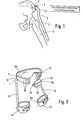
- Figure 3 shows the device of Figure 2 in a position where the hip is in flexion. There is an increase in leg abduction which results from the rotation of the leg bars (14, 15) about the inclined axis of their pivots (12, 13). The thigh bands (16, 17) have also rotated to a more anterior position.
- FIG 4 shows a diagrammatical view of the device of Figure 3 from above.
- the waist band (11) is shown with the anterior pressure pad (18) in position. This is a fixed position with the lugs (20, 21) fitted through the holes.
- the bends (25, 26) are shown in the leg bars (14, 15) so that the major portion of the leg bars (27, 28) lies substantially parallel to the leg when worn.
- the thigh bands (16, 17) are shown at one end of the leg bars (14, 15).
- the other end of the leg bars are held in pivots (12, 13) which are in turn attached to the waist band (11).
- the pivots (12, 13) are shown angled forward.
- FIG. 5 shows a rear view of the waist band (11) and the anterior pressure pad (18).
- the waist band (11) has a posterior expansion (29) which prevents rotation of the device and increases the area of contact with the sacrum thereby increasing the comfort in wearing the device.
- the posterior expansion (29) and the anterior pressure pad (18) act together to maintain the waist band (11) more or less parallel to the coronal plane.
- the muscles of adduction and internal rotation tend to draw the leg bars together particularly during hip flexion. This force when transmitted to the waist band tends to tilt it backwards, this is over come by upward pressure on the posterior expansion (29) and downward pressure on the anterior pressure pad (18).
- the pivots (12, 13) are shown having a downward inclination.
- the pivots (12, 13) are fixed in one position in this particular embodiment as shown by the screws and plate.
- FIG. 6 shows one means of allowing the angle of downwards inclination of the pivots (12, 13) to be varied.
- Each pivot carries a horizontal slot (30) through which passes a fixation bolt (31) which is able to move vertically in slot (32) but which can be tightened to hold each pivot (12, 13) in a given inclined configuration.
- FIG. 7 shows a second means altering the inclination of the pivots (33, 34) which may be individually altered.
- the pivots (33, 34) are attached to plates (35, 36) which each contain an arcuate slot (37, 38) in which there is a fixing bolt which passes through to a reinforcing plate (not shown) of the waist band (39).
- a spring clip (40, 41) may be used to interact in a groove in the leg bar to retain the leg bar in the pivot. By having more than one groove in each leg bar, the separation of the leg bars may be altered by selecting a different groove.
- Figure 8 shows an alternative means of variation of the inclination of the pivot means.
- the inclination of the pivot varies continually as the pivot rotates about an axis perpendicular to it.
- the pivot axis is inclined downwards in a manner shown in Figure 2.
- a pinion (43) at the end of the leg bar (44) engages a rack (42) on the waist band and the pinion (43) moves the pivot axis towards the horizontal during hip flexion.
- the pivot is horizontal and the leg bars overcome adductor tone without any further input of work from the wearer.
- the pivot axis represented by the line AC is inclined at an angle Y from the vertical.
- the angle Y may be varied using one the means illustrated in Figures 6, 7 or 8.
- the line AB joins the first bend of the leg bar to its tip.
- e is the angle between the line AB and the pivot axis AC.
- the end B of the leg bar When rotated about AC the end B of the leg bar describes the circular base of an inclined cone.
- the horizontal reflection of that circle is an ellipse and leg abduction, which occurs in the horizontal plane, may be calculated by the reflection of the tip of the leg bar onto that ellipse.
- the leg bars make an obtuse angle of 180- ⁇ ° with the axis of their.pivot.
- this obtuse angle is aptly greater than 90° and suitably is between 120° and 150° and preferably is between 130° and 140°, for example 135°.
Landscapes
- Health & Medical Sciences (AREA)
- Public Health (AREA)
- Veterinary Medicine (AREA)
- Engineering & Computer Science (AREA)
- Nursing (AREA)
- Heart & Thoracic Surgery (AREA)
- Vascular Medicine (AREA)
- Life Sciences & Earth Sciences (AREA)
- Animal Behavior & Ethology (AREA)
- Orthopedic Medicine & Surgery (AREA)
- General Health & Medical Sciences (AREA)
- Biomedical Technology (AREA)
- Orthopedics, Nursing, And Contraception (AREA)
- Mechanical Operated Clutches (AREA)
- Diaphragms For Electromechanical Transducers (AREA)
- Rehabilitation Tools (AREA)
- Prostheses (AREA)
- Pharmaceuticals Containing Other Organic And Inorganic Compounds (AREA)
- Exchange Systems With Centralized Control (AREA)
- Small-Scale Networks (AREA)
Priority Applications (1)
| Application Number | Priority Date | Filing Date | Title |
|---|---|---|---|
| AT87301793T ATE66131T1 (de) | 1986-03-05 | 1987-03-02 | Vorrichtung zur einschraenkung der beinbeweglichkeit. |
Applications Claiming Priority (2)
| Application Number | Priority Date | Filing Date | Title |
|---|---|---|---|
| GB868605472A GB8605472D0 (en) | 1986-03-05 | 1986-03-05 | Leg restraint |
| GB8605472 | 1986-03-05 |
Publications (2)
| Publication Number | Publication Date |
|---|---|
| EP0237242A1 true EP0237242A1 (fr) | 1987-09-16 |
| EP0237242B1 EP0237242B1 (fr) | 1991-08-14 |
Family
ID=10594106
Family Applications (1)
| Application Number | Title | Priority Date | Filing Date |
|---|---|---|---|
| EP87301793A Expired - Lifetime EP0237242B1 (fr) | 1986-03-05 | 1987-03-02 | Dispositif pour limiter le mouvement des jambes |
Country Status (9)
| Country | Link |
|---|---|
| US (1) | US4901710A (fr) |
| EP (1) | EP0237242B1 (fr) |
| JP (1) | JP2511447B2 (fr) |
| AT (1) | ATE66131T1 (fr) |
| AU (1) | AU599633B2 (fr) |
| CA (1) | CA1305000C (fr) |
| DE (1) | DE3772071D1 (fr) |
| GB (3) | GB8605472D0 (fr) |
| ZA (1) | ZA871559B (fr) |
Cited By (5)
| Publication number | Priority date | Publication date | Assignee | Title |
|---|---|---|---|---|
| GB2210794A (en) * | 1987-10-14 | 1989-06-21 | David Ernest Young | Orthopaedic body jacket |
| WO1992016177A1 (fr) * | 1991-03-13 | 1992-10-01 | Polycane Australia Pty. Ltd. | Orthese pour la marche |
| EP0557712A1 (fr) * | 1992-02-25 | 1993-09-01 | TRIMBORN MASCHINEN- UND APPARATEBAU GmbH | Stelle d'écartement |
| NL1031342C2 (nl) * | 2005-07-12 | 2007-02-20 | Somas Orthopaedie B V | Heupabductieorthese. |
| CN102846417A (zh) * | 2012-09-27 | 2013-01-02 | 胡大勇 | 动态稳定髋关节支具系统 |
Families Citing this family (22)
| Publication number | Priority date | Publication date | Assignee | Title |
|---|---|---|---|---|
| US5658242A (en) * | 1991-03-13 | 1997-08-19 | Polycane Australia Pty Ltd. | Walking aid |
| US5172703A (en) * | 1991-10-23 | 1992-12-22 | Michelle Tiede | Torsion control harness |
| US5295947A (en) * | 1992-04-29 | 1994-03-22 | H.E. Stanley Laboratories | Chiropractic brace |
| US5344391A (en) * | 1992-07-10 | 1994-09-06 | National Orthotic Laboratories | Hip abduction system |
| JP3986632B2 (ja) * | 1997-09-17 | 2007-10-03 | アルケア株式会社 | パッド付き股関節用サポーター |
| CA2241575A1 (fr) | 1998-06-23 | 1999-12-23 | Devin J. Ostrom | Raccord et prothese incorporant celui-ci |
| US6254559B1 (en) | 1999-08-30 | 2001-07-03 | Anthony C. Tyrrell | Adjustable hip joint assembly |
| US7758481B2 (en) * | 2002-09-04 | 2010-07-20 | Denis Burke Drennan | Dynamic hip stabilizer |
| DE102004020980A1 (de) * | 2004-04-23 | 2005-11-10 | Wilhelm Julius Teufel Gmbh | Modulare Hüftorthese |
| US7775999B2 (en) * | 2004-10-01 | 2010-08-17 | Randall Brown | Apparatus and method for use of a hip brace |
| NL1029502C2 (nl) * | 2005-07-12 | 2007-01-16 | Somas Groep B V | Heupabductieorthese. |
| JP2007090008A (ja) * | 2005-09-26 | 2007-04-12 | Izumi Ishikawa | 腰部ガードル |
| EA013306B1 (ru) * | 2008-04-08 | 2010-04-30 | Закрытое Акционерное Общество Научно-Производственный Центр "Огонёк" | Тазобедренный ортез для коррекции патологической установки бедра |
| JP5837040B2 (ja) * | 2010-03-31 | 2015-12-24 | ハロ イノベーションズ、インク. | 乳幼児股関節位置調整装置および関連方法 |
| US9931536B2 (en) * | 2012-09-14 | 2018-04-03 | Emily Azevedo | Hip harness |
| KR102483389B1 (ko) * | 2015-08-26 | 2022-12-30 | 삼성전자주식회사 | 골반 고정 기구 및 이를 포함하는 운동 보조 장치 |
| US20170274249A1 (en) * | 2016-03-23 | 2017-09-28 | Tau Orthopedics, Llc | Wearable resistance device with power monitoring |
| KR102014538B1 (ko) * | 2017-06-20 | 2019-08-26 | 건양대학교 산학협력단 | 골반 및 고관절 회전 조절이 가능한 보조기 |
| KR102100146B1 (ko) * | 2018-05-29 | 2020-04-13 | 백석대학교 산학협력단 | 하지 관절회전 조절을 통한 자세교정 보조기 |
| CN110801322B (zh) * | 2019-09-26 | 2021-11-16 | 深圳市泰康益民医疗科技发展有限公司 | 一种髋膝踝足矫形器 |
| US11995826B2 (en) * | 2021-12-16 | 2024-05-28 | Metal Industries Research & Development Centre | Auxiliary screening system and auxiliary screening method for a hip joint of a baby |
| CN114848331B (zh) * | 2022-05-14 | 2024-01-26 | 栗磊 | 一种抗下肢内收支具 |
Citations (3)
| Publication number | Priority date | Publication date | Assignee | Title |
|---|---|---|---|---|
| DE1263219B (de) * | 1962-10-08 | 1968-03-14 | S H Camp & Company | Abspreizschiene zur Behandlung der Praeluxation bei Kindern |
| GB1343850A (en) * | 1971-06-14 | 1974-01-16 | Thum O | Orthopaedic device for children |
| US4497315A (en) * | 1981-04-07 | 1985-02-05 | Otto Bock Orthopaedische Industrie Kg | Orthopedic device for treating hip displeasure and hip luxation |
Family Cites Families (5)
| Publication number | Priority date | Publication date | Assignee | Title |
|---|---|---|---|---|
| US3730177A (en) * | 1971-06-02 | 1973-05-01 | O Thum | Spreading bandage for children having dislocated hip bones |
| DE2714272C3 (de) * | 1977-03-31 | 1980-08-14 | Joachim Prof. Dr.Med. 6200 Wiesbaden Eichler | Spreizvorrichtung zur Behandlung von Hüftdysplasie |
| US4481941A (en) * | 1983-03-07 | 1984-11-13 | Rolfes Thomas A | Universal hip stabilization device |
| US4574790A (en) * | 1983-07-09 | 1986-03-11 | Otto Bock Orthopadische Industrie Kg | Orthopedic device for treating hip dysplasia and hip dislocation |
| DE3508844A1 (de) * | 1985-03-13 | 1986-09-18 | Fa. Wilhelm Julius Teufel, 7000 Stuttgart | Hueft-orthese fuer saeuglinge |
-
1986
- 1986-03-05 GB GB868605472A patent/GB8605472D0/en active Pending
-
1987
- 1987-03-02 AT AT87301793T patent/ATE66131T1/de not_active IP Right Cessation
- 1987-03-02 DE DE8787301793T patent/DE3772071D1/de not_active Expired - Lifetime
- 1987-03-02 EP EP87301793A patent/EP0237242B1/fr not_active Expired - Lifetime
- 1987-03-02 GB GB878704797A patent/GB8704797D0/en active Pending
- 1987-03-03 GB GB8704975A patent/GB2188240B/en not_active Expired - Lifetime
- 1987-03-04 ZA ZA871559A patent/ZA871559B/xx unknown
- 1987-03-04 US US07/021,772 patent/US4901710A/en not_active Expired - Lifetime
- 1987-03-04 CA CA000531158A patent/CA1305000C/fr not_active Expired - Lifetime
- 1987-03-05 JP JP62051854A patent/JP2511447B2/ja not_active Expired - Lifetime
- 1987-03-05 AU AU69742/87A patent/AU599633B2/en not_active Expired
Patent Citations (3)
| Publication number | Priority date | Publication date | Assignee | Title |
|---|---|---|---|---|
| DE1263219B (de) * | 1962-10-08 | 1968-03-14 | S H Camp & Company | Abspreizschiene zur Behandlung der Praeluxation bei Kindern |
| GB1343850A (en) * | 1971-06-14 | 1974-01-16 | Thum O | Orthopaedic device for children |
| US4497315A (en) * | 1981-04-07 | 1985-02-05 | Otto Bock Orthopaedische Industrie Kg | Orthopedic device for treating hip displeasure and hip luxation |
Cited By (8)
| Publication number | Priority date | Publication date | Assignee | Title |
|---|---|---|---|---|
| GB2210794A (en) * | 1987-10-14 | 1989-06-21 | David Ernest Young | Orthopaedic body jacket |
| WO1992016177A1 (fr) * | 1991-03-13 | 1992-10-01 | Polycane Australia Pty. Ltd. | Orthese pour la marche |
| EP0557712A1 (fr) * | 1992-02-25 | 1993-09-01 | TRIMBORN MASCHINEN- UND APPARATEBAU GmbH | Stelle d'écartement |
| NL1031342C2 (nl) * | 2005-07-12 | 2007-02-20 | Somas Orthopaedie B V | Heupabductieorthese. |
| WO2007008058A3 (fr) * | 2005-07-12 | 2007-04-05 | Somas Groep B V | Orthese d'abduction de la hanche |
| US8118764B2 (en) | 2005-07-12 | 2012-02-21 | Ossur Europe B.V. | Hip abduction orthosis |
| US8771214B2 (en) | 2005-07-12 | 2014-07-08 | Ossur Europe B.V. | Hip abduction orthosis |
| CN102846417A (zh) * | 2012-09-27 | 2013-01-02 | 胡大勇 | 动态稳定髋关节支具系统 |
Also Published As
| Publication number | Publication date |
|---|---|
| EP0237242B1 (fr) | 1991-08-14 |
| GB2188240B (en) | 1990-03-21 |
| JPS62253053A (ja) | 1987-11-04 |
| AU599633B2 (en) | 1990-07-26 |
| GB8605472D0 (en) | 1986-04-09 |
| US4901710A (en) | 1990-02-20 |
| ZA871559B (en) | 1987-10-28 |
| AU6974287A (en) | 1987-09-10 |
| JP2511447B2 (ja) | 1996-06-26 |
| GB8704975D0 (en) | 1987-04-08 |
| CA1305000C (fr) | 1992-07-14 |
| GB2188240A (en) | 1987-09-30 |
| ATE66131T1 (de) | 1991-08-15 |
| GB8704797D0 (en) | 1987-04-08 |
| DE3772071D1 (de) | 1991-09-19 |
Similar Documents
| Publication | Publication Date | Title |
|---|---|---|
| US4901710A (en) | Leg restraint | |
| US12433778B2 (en) | Orthopedic device for treating complications of the hip | |
| US5449338A (en) | Modular orthopedic brace | |
| US7758481B2 (en) | Dynamic hip stabilizer | |
| US7476185B2 (en) | Dynamic hip stabilizer | |
| US5295947A (en) | Chiropractic brace | |
| US10357391B2 (en) | Orthopedic device for treating complications of the hip | |
| US9987158B2 (en) | Orthopedic device for treating complications of the hip | |
| US7833182B2 (en) | Back support apparatus and method | |
| US4241731A (en) | Universal arm support | |
| US3750659A (en) | Orthopedic apparatus for legs to enable standing | |
| US5286251A (en) | Hip harness | |
| US4108168A (en) | Hip splint device | |
| EP3328327B1 (fr) | Dispositif orthopédique destiné à traiter des complications de la hanche | |
| US10610400B1 (en) | Selectively adjustable arm and shoulder support | |
| US9668902B1 (en) | Selectively adjustable arm and shoulder support | |
| Katz et al. | SEAT INSERT FOR CEREBRAL‐PALSIED CHILDREN WITH TOTAL BODY INVOLVEMENT | |
| Hannah et al. | Tubular orthoses | |
| Karfiol | Simplified arm sling | |
| Spellissy | VIII. I. An Improved Brace for Head Extension. II. A Hard Rubber Spring Brace for Lateral Curvature |
Legal Events
| Date | Code | Title | Description |
|---|---|---|---|
| PUAI | Public reference made under article 153(3) epc to a published international application that has entered the european phase |
Free format text: ORIGINAL CODE: 0009012 |
|
| AK | Designated contracting states |
Kind code of ref document: A1 Designated state(s): AT BE CH DE FR GB IT LI NL SE |
|
| 17P | Request for examination filed |
Effective date: 19871123 |
|
| 17Q | First examination report despatched |
Effective date: 19890717 |
|
| 18D | Application deemed to be withdrawn |
Effective date: 19891128 |
|
| 18RA | Request filed for re-establishment of rights before grant |
Effective date: 19900723 |
|
| 18RR | Decision to grant the request for re-establishment of rights before grant |
Free format text: 900925 ANGENOMMEN |
|
| D18D | Application deemed to be withdrawn (deleted) | ||
| REG | Reference to a national code |
Ref country code: DE Ref legal event code: 8570 |
|
| GRAA | (expected) grant |
Free format text: ORIGINAL CODE: 0009210 |
|
| AK | Designated contracting states |
Kind code of ref document: B1 Designated state(s): AT BE CH DE FR GB IT LI NL SE |
|
| REF | Corresponds to: |
Ref document number: 66131 Country of ref document: AT Date of ref document: 19910815 Kind code of ref document: T |
|
| REF | Corresponds to: |
Ref document number: 3772071 Country of ref document: DE Date of ref document: 19910919 |
|
| ITF | It: translation for a ep patent filed | ||
| ET | Fr: translation filed | ||
| PLBE | No opposition filed within time limit |
Free format text: ORIGINAL CODE: 0009261 |
|
| STAA | Information on the status of an ep patent application or granted ep patent |
Free format text: STATUS: NO OPPOSITION FILED WITHIN TIME LIMIT |
|
| 26N | No opposition filed | ||
| EAL | Se: european patent in force in sweden |
Ref document number: 87301793.3 |
|
| REG | Reference to a national code |
Ref country code: GB Ref legal event code: 732E |
|
| REG | Reference to a national code |
Ref country code: FR Ref legal event code: TP |
|
| REG | Reference to a national code |
Ref country code: CH Ref legal event code: PUE Owner name: BRITISH TECHNOLOGY GROUP INTER-CORPORATE LICENSING |
|
| NLS | Nl: assignments of ep-patents |
Owner name: BRITISH TECHNOLOGY GROUP INTER-CORPORATE LICENSING |
|
| ITPR | It: changes in ownership of a european patent |
Owner name: CESSIONE;BRITISH TECHNOLOGY GROUP INTER - CORPORAT |
|
| REG | Reference to a national code |
Ref country code: GB Ref legal event code: IF02 |
|
| PGFP | Annual fee paid to national office [announced via postgrant information from national office to epo] |
Ref country code: DE Payment date: 20060223 Year of fee payment: 20 |
|
| PGFP | Annual fee paid to national office [announced via postgrant information from national office to epo] |
Ref country code: CH Payment date: 20060301 Year of fee payment: 20 Ref country code: GB Payment date: 20060301 Year of fee payment: 20 |
|
| PGFP | Annual fee paid to national office [announced via postgrant information from national office to epo] |
Ref country code: NL Payment date: 20060305 Year of fee payment: 20 |
|
| PGFP | Annual fee paid to national office [announced via postgrant information from national office to epo] |
Ref country code: FR Payment date: 20060308 Year of fee payment: 20 |
|
| PGFP | Annual fee paid to national office [announced via postgrant information from national office to epo] |
Ref country code: AT Payment date: 20060313 Year of fee payment: 20 |
|
| PGFP | Annual fee paid to national office [announced via postgrant information from national office to epo] |
Ref country code: IT Payment date: 20060331 Year of fee payment: 20 |
|
| PGFP | Annual fee paid to national office [announced via postgrant information from national office to epo] |
Ref country code: BE Payment date: 20060509 Year of fee payment: 20 |
|
| PG25 | Lapsed in a contracting state [announced via postgrant information from national office to epo] |
Ref country code: GB Free format text: LAPSE BECAUSE OF EXPIRATION OF PROTECTION Effective date: 20070301 |
|
| PG25 | Lapsed in a contracting state [announced via postgrant information from national office to epo] |
Ref country code: NL Free format text: LAPSE BECAUSE OF EXPIRATION OF PROTECTION Effective date: 20070302 |
|
| REG | Reference to a national code |
Ref country code: GB Ref legal event code: PE20 |
|
| REG | Reference to a national code |
Ref country code: CH Ref legal event code: PL |
|
| NLV7 | Nl: ceased due to reaching the maximum lifetime of a patent |
Effective date: 20070302 |
|
| EUG | Se: european patent has lapsed | ||
| BE20 | Be: patent expired |
Owner name: *BRITISH TECHNOLOGY GROUP INTER-CORPORATE LICENSIN Effective date: 20070302 |
|
| PGFP | Annual fee paid to national office [announced via postgrant information from national office to epo] |
Ref country code: SE Payment date: 20060306 Year of fee payment: 20 |