EP0237755A2 - Dispositif pour le changement continu de la longueur d'un tube d'aspiration d'air d'un moteur à combustion interne - Google Patents
Dispositif pour le changement continu de la longueur d'un tube d'aspiration d'air d'un moteur à combustion interne Download PDFInfo
- Publication number
- EP0237755A2 EP0237755A2 EP87101604A EP87101604A EP0237755A2 EP 0237755 A2 EP0237755 A2 EP 0237755A2 EP 87101604 A EP87101604 A EP 87101604A EP 87101604 A EP87101604 A EP 87101604A EP 0237755 A2 EP0237755 A2 EP 0237755A2
- Authority
- EP
- European Patent Office
- Prior art keywords
- rotating body
- internal combustion
- combustion engine
- housing
- wall
- Prior art date
- Legal status (The legal status is an assumption and is not a legal conclusion. Google has not performed a legal analysis and makes no representation as to the accuracy of the status listed.)
- Withdrawn
Links
Images

Classifications
-
- F—MECHANICAL ENGINEERING; LIGHTING; HEATING; WEAPONS; BLASTING
- F02—COMBUSTION ENGINES; HOT-GAS OR COMBUSTION-PRODUCT ENGINE PLANTS
- F02M—SUPPLYING COMBUSTION ENGINES IN GENERAL WITH COMBUSTIBLE MIXTURES OR CONSTITUENTS THEREOF
- F02M35/00—Combustion-air cleaners, air intakes, intake silencers, or induction systems specially adapted for, or arranged on, internal-combustion engines
- F02M35/10—Air intakes; Induction systems
-
- F—MECHANICAL ENGINEERING; LIGHTING; HEATING; WEAPONS; BLASTING
- F02—COMBUSTION ENGINES; HOT-GAS OR COMBUSTION-PRODUCT ENGINE PLANTS
- F02B—INTERNAL-COMBUSTION PISTON ENGINES; COMBUSTION ENGINES IN GENERAL
- F02B27/00—Use of kinetic or wave energy of charge in induction systems, or of combustion residues in exhaust systems, for improving quantity of charge or for increasing removal of combustion residues
- F02B27/02—Use of kinetic or wave energy of charge in induction systems, or of combustion residues in exhaust systems, for improving quantity of charge or for increasing removal of combustion residues the systems having variable, i.e. adjustable, cross-sectional areas, chambers of variable volume, or like variable means
- F02B27/0226—Use of kinetic or wave energy of charge in induction systems, or of combustion residues in exhaust systems, for improving quantity of charge or for increasing removal of combustion residues the systems having variable, i.e. adjustable, cross-sectional areas, chambers of variable volume, or like variable means characterised by the means generating the charging effect
- F02B27/0247—Plenum chambers; Resonance chambers or resonance pipes
- F02B27/0257—Rotatable plenum chambers
-
- F—MECHANICAL ENGINEERING; LIGHTING; HEATING; WEAPONS; BLASTING
- F02—COMBUSTION ENGINES; HOT-GAS OR COMBUSTION-PRODUCT ENGINE PLANTS
- F02B—INTERNAL-COMBUSTION PISTON ENGINES; COMBUSTION ENGINES IN GENERAL
- F02B27/00—Use of kinetic or wave energy of charge in induction systems, or of combustion residues in exhaust systems, for improving quantity of charge or for increasing removal of combustion residues
- F02B27/02—Use of kinetic or wave energy of charge in induction systems, or of combustion residues in exhaust systems, for improving quantity of charge or for increasing removal of combustion residues the systems having variable, i.e. adjustable, cross-sectional areas, chambers of variable volume, or like variable means
- F02B27/0205—Use of kinetic or wave energy of charge in induction systems, or of combustion residues in exhaust systems, for improving quantity of charge or for increasing removal of combustion residues the systems having variable, i.e. adjustable, cross-sectional areas, chambers of variable volume, or like variable means characterised by the charging effect
- F02B27/0215—Oscillating pipe charging, i.e. variable intake pipe length charging
-
- F—MECHANICAL ENGINEERING; LIGHTING; HEATING; WEAPONS; BLASTING
- F02—COMBUSTION ENGINES; HOT-GAS OR COMBUSTION-PRODUCT ENGINE PLANTS
- F02B—INTERNAL-COMBUSTION PISTON ENGINES; COMBUSTION ENGINES IN GENERAL
- F02B27/00—Use of kinetic or wave energy of charge in induction systems, or of combustion residues in exhaust systems, for improving quantity of charge or for increasing removal of combustion residues
- F02B27/02—Use of kinetic or wave energy of charge in induction systems, or of combustion residues in exhaust systems, for improving quantity of charge or for increasing removal of combustion residues the systems having variable, i.e. adjustable, cross-sectional areas, chambers of variable volume, or like variable means
- F02B27/0226—Use of kinetic or wave energy of charge in induction systems, or of combustion residues in exhaust systems, for improving quantity of charge or for increasing removal of combustion residues the systems having variable, i.e. adjustable, cross-sectional areas, chambers of variable volume, or like variable means characterised by the means generating the charging effect
- F02B27/0247—Plenum chambers; Resonance chambers or resonance pipes
- F02B27/0263—Plenum chambers; Resonance chambers or resonance pipes the plenum chamber and at least one of the intake ducts having a common wall, and the intake ducts wrap partially around the plenum chamber, i.e. snail-type
-
- F—MECHANICAL ENGINEERING; LIGHTING; HEATING; WEAPONS; BLASTING
- F02—COMBUSTION ENGINES; HOT-GAS OR COMBUSTION-PRODUCT ENGINE PLANTS
- F02B—INTERNAL-COMBUSTION PISTON ENGINES; COMBUSTION ENGINES IN GENERAL
- F02B75/00—Other engines
- F02B75/16—Engines characterised by number of cylinders, e.g. single-cylinder engines
- F02B75/18—Multi-cylinder engines
- F02B2075/1804—Number of cylinders
- F02B2075/1816—Number of cylinders four
-
- F—MECHANICAL ENGINEERING; LIGHTING; HEATING; WEAPONS; BLASTING
- F02—COMBUSTION ENGINES; HOT-GAS OR COMBUSTION-PRODUCT ENGINE PLANTS
- F02B—INTERNAL-COMBUSTION PISTON ENGINES; COMBUSTION ENGINES IN GENERAL
- F02B3/00—Engines characterised by air compression and subsequent fuel addition
- F02B3/06—Engines characterised by air compression and subsequent fuel addition with compression ignition
-
- Y—GENERAL TAGGING OF NEW TECHNOLOGICAL DEVELOPMENTS; GENERAL TAGGING OF CROSS-SECTIONAL TECHNOLOGIES SPANNING OVER SEVERAL SECTIONS OF THE IPC; TECHNICAL SUBJECTS COVERED BY FORMER USPC CROSS-REFERENCE ART COLLECTIONS [XRACs] AND DIGESTS
- Y02—TECHNOLOGIES OR APPLICATIONS FOR MITIGATION OR ADAPTATION AGAINST CLIMATE CHANGE
- Y02T—CLIMATE CHANGE MITIGATION TECHNOLOGIES RELATED TO TRANSPORTATION
- Y02T10/00—Road transport of goods or passengers
- Y02T10/10—Internal combustion engine [ICE] based vehicles
- Y02T10/12—Improving ICE efficiencies
Definitions
- the invention relates to a device for continuously changing the length of the air intake pipe of an internal combustion engine according to the preamble of the main claim. It is already a device for stepless change in the length of the air intake pipe of an internal combustion engine is known, but in which there is a very large space requirement and control and sealing problems impair the effectiveness.
- the device according to the invention with the characterizing features of the main claim has the advantage that it ensures a continuous change in the length of the air intake pipe with the smallest possible space requirement and without changing the space requirement over a large area and is easy to control and seal.
- the device according to the invention enables the corresponding, optimal air intake pipe length to be continuously assigned to any desired full-load speed during driving of the internal combustion engine, so that the maximum possible torque curve results over the entire speed range and discontinuities in the torque curve are avoided.
- helically twist angle can wrden realized over 360, causing the leaves infinitely vari- i e rbare intake pipe length depending on the number of helical coils increased indefinitely, or, viewed differently, it can be for a given intake manifold of the housing diameter and thus the space requirement greatly reduce the suction system.
- Another advantage is the possibility of arranging an air filter and / or an air measuring element in the interior of the rotating body, so that the space requirement for the entire air intake system is reduced.
- FIG. 1 shows a first exemplary embodiment of a device according to the invention for continuously changing the length of the air intake pipe of an internal combustion engine
- FIG. 2 shows a section along the line II-II in FIG. 1
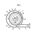
- FIG. 3 shows a second exemplary embodiment of a device according to the invention for continuously changing the length of the air intake pipe of an internal combustion engine Internal combustion engine in cross section.
- the first exemplary embodiment of a device according to the invention for continuously changing the length of the air intake pipe of an internal combustion engine according to FIGS. 1 and 2 is explained on the basis of a mixture-compressing spark-ignition internal combustion engine.
- an air intake pipe 2 leads from an air filter 1 to a manifold intake pipe with a housing 3.
- an intake duct 4 leads to a cylinder of a mixture-compressing spark-ignition internal combustion engine 5.
- the outlets of the cylinders of the internal combustion engine 5 are connected to an exhaust pipe 6.
- a throttle valve 7, which can be actuated by a so-called accelerator pedal 8, is arranged in the air intake pipe 2.
- An air measuring element 9 is arranged in the air intake pipe 2 between the air filter 1 and the throttle valve 7 and is used to determine the amount of air sucked in by the internal combustion engine.
- the air measuring element 9 can be formed, for example, as a damper, hot wire, hot film or otherwise.
- the value of the intake air quantity determined by the air measuring element 9 is entered in the form of an electrical signal 10 in an electronic control unit 11.
- the angular position of the throttle valve 7 in the air intake pipe 2 is determined by a so-called throttle valve generator 13 and is input to the electronic control unit 11 as an electrical signal 14.
- a speed sensor not shown, determines the speed of the internal combustion engine, which can be input to the electronic control unit 11 as an electrical value 15.
- the speed can also be determined in a manner not shown on the basis of the ignition pulses.
- an electromagnetically actuated fuel injection valve 16 of a known type is arranged in the immediate vicinity of the cylinders of the internal combustion engine 5.
- the electromagnetically actuated fuel injection valves 16 can be controlled by the electronic control unit 11 as a function of the operating parameters of the internal combustion engine 5, such as temperature, air intake quantity, speed, throttle valve position and others, which are supplied to the electronic control unit 11.
- hydraulically opening fuel injection valves of a so-called mechanical fuel injection system can also be arranged automatically.
- the housing 3 serving as a manifold is stationary on the internal combustion engine 5 or in the engine compartment of a motor vehicle Stigt and is sealed on its end faces transverse to the longitudinal axis 17, for example on its end face facing the air intake pipe 2 by a cover 19 and on its opposite end face by a cover 20.
- the housing 3 is preferably cylindrical, with a circular inner wall 21.
- a hollow cylindrical rotating body 23 is rotatably mounted concentrically to the longitudinal axis 17.
- the hollow cylindrical rotating body 23 is located at a radial distance a between its jacket 22 and the inner wall 21 of the housing 3 within the housing 3.
- the rotating body 23 can be closed transversely to the longitudinal axis 17 on its end faces, for example on its end face facing the air intake pipe 2 by a cover 25.
- the cover 25 can also be firmly connected to the housing 3, as a result of which the rotary movement between the cover 25 and the air intake pipe 2 would be eliminated.
- the rotating body 23 encloses an interior space 26 which is connected to the air intake pipe 2 via a connecting opening 27.
- outlet openings 29 are provided in the tubular wall 28 of the rotating body 23 from the interior 26 to the jacket 22, so that each intake duct 4 of a cylinder of the internal combustion engine is assigned an outlet opening 29.
- Each outlet opening 29 opens out on the jacket 22 of the rotating body 23 in a flow channel 31, which is assigned to only one intake channel 4 and is limited in the radial direction by the jacket 22 of the rotating body 23 or the inner wall 21 of the housing 3, while the axial limitation to adjacent flow channel through sealing walls 32 arranged between the flow channels 31, which extend radially between the jacket 22 of the rotating body 23 and the inner wall 21 of the housing 3. Facing the cylinders of the internal combustion engine 5, the intake ducts 4 protrude at least partially through the housing wall 33 of the housing 3 so that their Inlet openings 34 facing away from the cylinders are each open to one of the flow channels 31, that is to say a flow connection is established between each of the flow channels 31 and one of the intake channels 4.
- each flow channel 31 has a constant cross section over its entire length from the outlet opening 29 to the inlet opening 34.
- the length of each effective flow channel 31 between each outlet opening 29 on the rotating body 23 and each inlet opening 34 is determined in each case from the rotational position of the rotating body 23 relative to the housing 3. In the exemplary embodiment shown in FIG. 2, the length of each flow channel 31 is reduced when the rotating body rotates 23 counterclockwise and lengthens when the rotating body 23 rotates clockwise.
- the rotating body 23 can advantageously be rotated depending on the operating parameters of the internal combustion engine in order to change the air column of the air intake pipe.
- a servomotor 37 known per se can be used which rotates the rotating body 23 in a manner not shown, for example directly or by means of a gear transmission.
- the servomotor 37 can operate pneumatically as a function of the intake manifold pressure or, as shown, electromagnetically and can be controlled by the electronic control unit 11.
- the servomotor 37 is preferably controlled by the electronic control unit 11 in dependence on the throttle valve position 14 and the speed 15 in such a way that it rotates the rotating body 23 into one position when the internal combustion engine is operating at full load in the lower speed range rotated, in which there is a long flow channel 31 for each cylinder between the outlet opening 29 of the rotating body 23 and the inlet opening 34, while it rotates at high speeds body 23 rotated counterclockwise, so that the outlet opening 29 comes closer to the inlet opening 34 of each intake duct 4 in the direction of rotation and thus the effective flow channel 31 between each outlet opening 29 and each inlet opening 34 is shortened.
- housing 3 and rotating body 23 are not arranged coaxially to one another but eccentrically to one another, so that their longitudinal axes 17, 40 are at the same height but at a distance b from one another have so that the radial distance a between the casing 22 of the rotating body 23 and the inner wall 21 of the housing 3 changes over the length of each flow channel 31 in such a way that the radial distance a increases in the counterclockwise direction, which increases with shortening flow channel 31 results in an increase in cross section of the flow channel 31.
- This cross-sectional profile of the flow duct 31 as a function of the length of the flow duct is quite desirable and advantageous, since there is an improvement in torque in the lower speed range of the full load for long air intake pipes with small cross sections and at high speeds for short air intake pipes with large cross sections.
- an air filter is shown with a dash-dot line at 38, which instead of the air filter 1 in FIG 1 can be arranged both in the first and in the second exemplary embodiment in the interior 26 of the rotating body 23.
- An air measuring element 39 for example in the form of a known hot film air mass meter, which is shown in broken lines and replaces the air measuring element 9 according to FIG. 1, can also be arranged in the interior 26 of the rotating body 23.
- the arrangement of an air filter 38 and / or an air measuring element 39 within the rotating body 23 leads to a reduction in the space requirement of the entire intake system of the internal combustion engine.
- the devices according to the invention according to FIGS. 2 and 3 can also be used in an equivalent manner in the air intake system of a diesel internal combustion engine, the electromagnetically actuated fuel injection valve 16 shown in FIG. 2 naturally being omitted.
Landscapes
- Engineering & Computer Science (AREA)
- Chemical & Material Sciences (AREA)
- Combustion & Propulsion (AREA)
- Mechanical Engineering (AREA)
- General Engineering & Computer Science (AREA)
- Characterised By The Charging Evacuation (AREA)
Applications Claiming Priority (2)
| Application Number | Priority Date | Filing Date | Title |
|---|---|---|---|
| DE3608310 | 1986-03-13 | ||
| DE19863608310 DE3608310A1 (de) | 1986-03-13 | 1986-03-13 | Vorrichtung zur stufenlosen veraenderung der laenge des luftansaugrohres einer brennkraftmaschine |
Publications (2)
| Publication Number | Publication Date |
|---|---|
| EP0237755A2 true EP0237755A2 (fr) | 1987-09-23 |
| EP0237755A3 EP0237755A3 (fr) | 1988-04-20 |
Family
ID=6296206
Family Applications (1)
| Application Number | Title | Priority Date | Filing Date |
|---|---|---|---|
| EP87101604A Withdrawn EP0237755A3 (fr) | 1986-03-13 | 1987-02-06 | Dispositif pour le changement continu de la longueur d'un tube d'aspiration d'air d'un moteur à combustion interne |
Country Status (5)
| Country | Link |
|---|---|
| EP (1) | EP0237755A3 (fr) |
| JP (1) | JPS62214223A (fr) |
| KR (1) | KR870009121A (fr) |
| BR (1) | BR8701142A (fr) |
| DE (1) | DE3608310A1 (fr) |
Cited By (8)
| Publication number | Priority date | Publication date | Assignee | Title |
|---|---|---|---|---|
| FR2682431A1 (fr) * | 1991-10-15 | 1993-04-16 | Dev Produits Nouveaux | Collecteur d'admission pour moteur thermique. |
| EP0728918B1 (fr) * | 1995-02-23 | 1999-03-10 | FILTERWERK MANN & HUMMEL GMBH | Dispositif d'admissions pour moteur à combustion de type à pistons |
| US5950587A (en) * | 1998-07-22 | 1999-09-14 | Basf Corporation | Continuously variable runner length manifold |
| DE19848662A1 (de) * | 1998-10-22 | 2000-04-27 | Bayerische Motoren Werke Ag | Ansaugvorrichtung für Brennkraftmaschinen mit längenänderbaren Saugleitungen |
| WO2000049280A1 (fr) * | 1999-02-18 | 2000-08-24 | Filterwerk Mann+Hummel Gmbh | Dispositif d'aspiration |
| DE4028489B4 (de) * | 1990-09-07 | 2005-06-23 | Adam Opel Ag | Luftangsaugeinrichtung für eine Brennkraftmaschine |
| WO2006092948A1 (fr) * | 2005-02-28 | 2006-09-08 | Toyota Jidosha Kabushiki Kaisha | Dispositif d'amenee pour moteur a combustion interne |
| CN112128029A (zh) * | 2020-09-24 | 2020-12-25 | 安徽江淮汽车集团股份有限公司 | 一种智能型进气系统及进气控制方法 |
Families Citing this family (11)
| Publication number | Priority date | Publication date | Assignee | Title |
|---|---|---|---|---|
| DE3807193A1 (de) * | 1988-03-04 | 1989-06-01 | Bayerische Motoren Werke Ag | Ansaugvorrichtung fuer eine brennkraftmaschine |
| DE3807159A1 (de) * | 1988-03-04 | 1989-09-14 | Bayerische Motoren Werke Ag | Saugrohr einer brennkraftmaschine |
| DE4005973A1 (de) * | 1990-02-26 | 1991-09-05 | Bosch Gmbh Robert | Diagnoseverfahren zur ueberpruefung von stellgliedern zur steuerung von brennkraftmaschinen |
| DE4435741C5 (de) * | 1994-10-06 | 2007-05-31 | Robert Bosch Gmbh | Verfahren und Vorrichtung zur Steuerung einer Brennkraftmaschine |
| JP3304751B2 (ja) * | 1996-03-29 | 2002-07-22 | トヨタ自動車株式会社 | 内燃機関の吸気通路構造 |
| JPH1061445A (ja) * | 1996-06-14 | 1998-03-03 | Toyota Motor Corp | 内燃機関の過給装置 |
| US6546789B1 (en) | 1997-06-30 | 2003-04-15 | Robert Bosch Gmbh | Method and arrangement for monitoring the operation of an intake-manifold flap for switching over the intake manifold of an internal combustion engine |
| DE19855734A1 (de) | 1998-12-03 | 2000-06-08 | Mann & Hummel Filter | Verstellbares Saugrohr |
| DE19948660A1 (de) | 1999-10-08 | 2001-04-12 | Mann & Hummel Filter | Ansaugvorrichtung |
| RU2241838C1 (ru) * | 2003-04-04 | 2004-12-10 | Оао "Автоваз" | Впускное устройство двигателя внутреннего сгорания с изменяемой длиной каналов |
| DE102013008686A1 (de) * | 2013-05-22 | 2014-11-27 | Volkswagen Aktiengesellschaft | Schaltsaugrohr |
Family Cites Families (4)
| Publication number | Priority date | Publication date | Assignee | Title |
|---|---|---|---|---|
| GB1012425A (en) * | 1964-04-01 | 1965-12-08 | Alfa Romeo Spa | Resonance induction device for internal-combustion engines |
| KR890000569B1 (ko) * | 1983-09-13 | 1989-03-21 | 미쯔비시 지도샤 고교 가부시끼 가이샤 | 엔진의 흡기통로길이 가변장치 |
| DE3446377C2 (de) * | 1983-12-21 | 1994-05-05 | Mazda Motor | Ansaugvorrichtung für eine Kolben-Brennkraftmaschine |
| US4592310A (en) * | 1984-01-26 | 1986-06-03 | Mazda Motor Corporation | Intake device for internal combustion engine |
-
1986
- 1986-03-13 DE DE19863608310 patent/DE3608310A1/de not_active Withdrawn
-
1987
- 1987-02-06 EP EP87101604A patent/EP0237755A3/fr not_active Withdrawn
- 1987-03-06 JP JP62050450A patent/JPS62214223A/ja active Pending
- 1987-03-12 BR BR8701142A patent/BR8701142A/pt not_active IP Right Cessation
- 1987-03-13 KR KR870002254A patent/KR870009121A/ko not_active Withdrawn
Cited By (11)
| Publication number | Priority date | Publication date | Assignee | Title |
|---|---|---|---|---|
| DE4028489B4 (de) * | 1990-09-07 | 2005-06-23 | Adam Opel Ag | Luftangsaugeinrichtung für eine Brennkraftmaschine |
| FR2682431A1 (fr) * | 1991-10-15 | 1993-04-16 | Dev Produits Nouveaux | Collecteur d'admission pour moteur thermique. |
| EP0728918B1 (fr) * | 1995-02-23 | 1999-03-10 | FILTERWERK MANN & HUMMEL GMBH | Dispositif d'admissions pour moteur à combustion de type à pistons |
| US5950587A (en) * | 1998-07-22 | 1999-09-14 | Basf Corporation | Continuously variable runner length manifold |
| DE19848662A1 (de) * | 1998-10-22 | 2000-04-27 | Bayerische Motoren Werke Ag | Ansaugvorrichtung für Brennkraftmaschinen mit längenänderbaren Saugleitungen |
| WO2000049280A1 (fr) * | 1999-02-18 | 2000-08-24 | Filterwerk Mann+Hummel Gmbh | Dispositif d'aspiration |
| WO2006092948A1 (fr) * | 2005-02-28 | 2006-09-08 | Toyota Jidosha Kabushiki Kaisha | Dispositif d'amenee pour moteur a combustion interne |
| US7270103B2 (en) | 2005-02-28 | 2007-09-18 | Toyota Jidosha Kabushiki Kaisha | Intake apparatus of internal combustion engine |
| CN101166894B (zh) * | 2005-02-28 | 2010-05-19 | 丰田自动车株式会社 | 内燃机进气装置 |
| CN112128029A (zh) * | 2020-09-24 | 2020-12-25 | 安徽江淮汽车集团股份有限公司 | 一种智能型进气系统及进气控制方法 |
| CN112128029B (zh) * | 2020-09-24 | 2021-08-17 | 安徽江淮汽车集团股份有限公司 | 一种智能型进气系统及进气控制方法 |
Also Published As
| Publication number | Publication date |
|---|---|
| BR8701142A (pt) | 1988-01-05 |
| KR870009121A (ko) | 1987-10-23 |
| DE3608310A1 (de) | 1987-09-17 |
| JPS62214223A (ja) | 1987-09-21 |
| EP0237755A3 (fr) | 1988-04-20 |
Similar Documents
| Publication | Publication Date | Title |
|---|---|---|
| EP0237755A2 (fr) | Dispositif pour le changement continu de la longueur d'un tube d'aspiration d'air d'un moteur à combustion interne | |
| EP0177794B1 (fr) | Dispositif d'admission pour moteurs polycylindriques | |
| EP0389834B1 (fr) | Arrangement des conduits d'admission pour un moteur à combustion à plusieurs cylindres | |
| DE10212596B4 (de) | Variable Einlassvorrichtung für einen Mehrzylinderverbrennungsmotor | |
| EP0645530B1 (fr) | Moteur à combustion interne avec système d'admission d'air | |
| DE3429414A1 (de) | Lufteinlasssystem fuer verbrennungsmotoren | |
| DE102007033675A1 (de) | Abgasrückführvorrichtung für eine Verbrennungskraftmaschine | |
| EP0987412A2 (fr) | Système d'admission | |
| DE68916158T2 (de) | Einlassanordnung für Brennkraftmaschine mit V-förmig angeordneten Zylinderreihen. | |
| EP0731878B1 (fr) | Dispositif de regulation du regime de ralenti d'un moteur a combustion interne | |
| DE3529388C2 (fr) | ||
| WO1996002743A1 (fr) | Dispositif d'admission d'air avec pipes d'admission de longueur variable | |
| EP1607615B1 (fr) | Système d'admission d'air pour un moteur à combustion interne avec au moins deux bancs de cylindres | |
| WO2000011332A1 (fr) | Dispositif d'aspiration pour moteur a combustion interne | |
| DE69611876T2 (de) | Brennkraftmaschine mit Einlasssystem mit veränderlicher Geometrie für ein Fahrzeug | |
| EP0728918B1 (fr) | Dispositif d'admissions pour moteur à combustion de type à pistons | |
| WO1997021025A2 (fr) | Dispositif d'aspiration d'air d'un moteur a combustion interne | |
| DE3923924C2 (de) | Steuervorrichtung für das Saugrohrsystem einer Fahrzeugbrennkraftmaschine | |
| DE102008024571B4 (de) | Abgasrückführvorrichtung für eine Verbrennungskraftmaschine | |
| EP0868598B1 (fr) | Systeme d'aspiration d'air a longueur variable du tuyau d'aspiration pour moteur a combustion interne | |
| AT404162B (de) | Schaltelement für brennkraftmaschinen | |
| DE10303701B4 (de) | Verfahren und Vorrichtung zum Steuern einer Brennkraftmaschine | |
| DE69600778T2 (de) | Lufteinlassleitung mit variabelen Rohrlängen | |
| DE3807159A1 (de) | Saugrohr einer brennkraftmaschine | |
| DE19820245A1 (de) | Ansaugsystem für eine Brennkraftmaschine |
Legal Events
| Date | Code | Title | Description |
|---|---|---|---|
| PUAI | Public reference made under article 153(3) epc to a published international application that has entered the european phase |
Free format text: ORIGINAL CODE: 0009012 |
|
| AK | Designated contracting states |
Kind code of ref document: A2 Designated state(s): DE FR GB IT |
|
| PUAL | Search report despatched |
Free format text: ORIGINAL CODE: 0009013 |
|
| AK | Designated contracting states |
Kind code of ref document: A3 Designated state(s): DE FR GB IT |
|
| STAA | Information on the status of an ep patent application or granted ep patent |
Free format text: STATUS: THE APPLICATION IS DEEMED TO BE WITHDRAWN |
|
| 18D | Application deemed to be withdrawn |
Effective date: 19881021 |
|
| RIN1 | Information on inventor provided before grant (corrected) |
Inventor name: LENZ, PROF. DR. HANS Inventor name: SCHWARZ, DR. HELMUT, DIPL.-PHYS. Inventor name: PACHTA-REYHOFEN, DR. GEORG |