EP0237807B1 - Verfahren zum Übertragen von Informationen sowie Anwendungen - Google Patents
Verfahren zum Übertragen von Informationen sowie Anwendungen Download PDFInfo
- Publication number
- EP0237807B1 EP0237807B1 EP87102181A EP87102181A EP0237807B1 EP 0237807 B1 EP0237807 B1 EP 0237807B1 EP 87102181 A EP87102181 A EP 87102181A EP 87102181 A EP87102181 A EP 87102181A EP 0237807 B1 EP0237807 B1 EP 0237807B1
- Authority
- EP
- European Patent Office
- Prior art keywords
- transmission
- information
- pst1
- pstn
- subscriber stations
- Prior art date
- Legal status (The legal status is an assumption and is not a legal conclusion. Google has not performed a legal analysis and makes no representation as to the accuracy of the status listed.)
- Expired - Lifetime
Links
- 230000005540 biological transmission Effects 0.000 title claims description 42
- 238000000034 method Methods 0.000 title claims description 17
- 230000003287 optical effect Effects 0.000 claims description 5
- 230000008878 coupling Effects 0.000 claims description 4
- 238000010168 coupling process Methods 0.000 claims description 4
- 238000005859 coupling reaction Methods 0.000 claims description 4
- 239000003365 glass fiber Substances 0.000 claims description 2
- 101100148606 Caenorhabditis elegans pst-1 gene Proteins 0.000 claims 7
- 230000002349 favourable effect Effects 0.000 claims 1
- 230000002093 peripheral effect Effects 0.000 description 9
- 238000010586 diagram Methods 0.000 description 5
- 239000000835 fiber Substances 0.000 description 5
- 230000006870 function Effects 0.000 description 3
- 230000001360 synchronised effect Effects 0.000 description 3
- 238000004891 communication Methods 0.000 description 2
- 238000003466 welding Methods 0.000 description 2
- 239000004020 conductor Substances 0.000 description 1
- 238000011161 development Methods 0.000 description 1
- 230000018109 developmental process Effects 0.000 description 1
- 150000002500 ions Chemical class 0.000 description 1
- 239000013307 optical fiber Substances 0.000 description 1
- 230000008520 organization Effects 0.000 description 1
Images


Classifications
-
- H—ELECTRICITY
- H04—ELECTRIC COMMUNICATION TECHNIQUE
- H04B—TRANSMISSION
- H04B7/00—Radio transmission systems, i.e. using radiation field
- H04B7/24—Radio transmission systems, i.e. using radiation field for communication between two or more posts
- H04B7/26—Radio transmission systems, i.e. using radiation field for communication between two or more posts at least one of which is mobile
- H04B7/2643—Radio transmission systems, i.e. using radiation field for communication between two or more posts at least one of which is mobile using time-division multiple access [TDMA]
-
- H—ELECTRICITY
- H04—ELECTRIC COMMUNICATION TECHNIQUE
- H04B—TRANSMISSION
- H04B10/00—Transmission systems employing electromagnetic waves other than radio-waves, e.g. infrared, visible or ultraviolet light, or employing corpuscular radiation, e.g. quantum communication
-
- H—ELECTRICITY
- H04—ELECTRIC COMMUNICATION TECHNIQUE
- H04B—TRANSMISSION
- H04B7/00—Radio transmission systems, i.e. using radiation field
- H04B7/14—Relay systems
- H04B7/15—Active relay systems
- H04B7/204—Multiple access
- H04B7/212—Time-division multiple access [TDMA]
Definitions
- the invention relates to methods according to the preamble of claim 1.
- a satellite transmission network which operates according to such a method is known from US-A-4,381,562.
- the information received from the satellite is temporarily stored and re-transmitted in a predetermined format in the next frame.
- a satellite relay station is known with a reception timing detector for measuring the frame timing of each information signal in connection with a signal storage circuit.
- a control device for controlling the memory operations of the signal memory circuit is provided for signal processing.
- the satellite communication system according to DE 32 02 656 A1 consists of an earth station and one or more relay stations in the form of satellites.
- a radio-based message transmission system is known with a relay station in near-air space.
- This relay station also fulfills the functions of a central station, ie in this case the organization of radio communication.
- the information from the subscriber stations is called up at different times by a call signal from the central station.
- EP-A-0 082 037 describes a digital transmission system between several participants using an optical bus structure.
- the bus operation is managed by a central control. Address information is preceded by the participant messages, which are evaluated in the central control and saved if necessary.
- the European patent application publication number 0 166 892 A1 describes a TDMA point to multipoint transmission system with a central station and several substations, in which the transmission band is also used several times. For this purpose, bursts are sent from the central station to the substations in the TDMA frame, first to the most distant substation with respect to the central station and last to the closest substation. The bursts of the substations are sent to the central station in reverse order. This frame structure means that there are only short pauses between the send and receive cycles.
- the invention has for its object to provide a method according to the preamble of claim 1, which is suitable for the terrestrial area and in which the transmission time is better organized. Applications of this method are also to be shown.
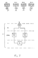
- Figure 1 shows a basic arrangement of a transmission network with central station ZSt, subscriber stations PSt and converter U.
- Figure 2 shows a block diagram of a transmission network according to the invention.
- Figure 3 shows a block diagram of a transmission network according to the invention with radio transmission.
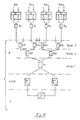
- FIG. 4 shows a block diagram of a transmission network according to the invention with transmission via glass fibers.
- Figure 5 shows a block diagram of a transmission network according to the invention with combined radio and fiber optic transmission.
- FIG. 6 shows a frame structure in arrangements according to FIGS. 3 to 5 as it occurs in amplifier V.
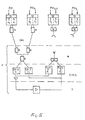
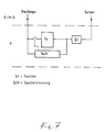
- Figure 7 shows the block diagram of an amplifier V for two-wire operation.
- Figure 8 shows a frame structure in two-wire operation.
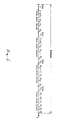
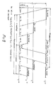
- Figure 9 shows the runtime conditions.
- PSt satellite network with several ground stations
- ZSt control station
- the operation takes place in the TDMA method ( Figure 2 and Figure 3).
- the same arrangement can also be operated on a terrestrial basis in a ladder-based manner.
- FIG. 4 Such a network is shown in FIG. 4 with fiber optic transmission.
- Passive optical couplers welding couplers
- the central station takes into account the specific running time ( ⁇ ) of the respective transmission medium when the runtime is reserved for the individual stations.
- converter U It is advantageous to use a relay station, hereinafter referred to as converter U, in such a terrestrial network, particularly when the converter is attached to an exposed location.
- Figures 3, 4 and 5 initially relate to four-wire transmission with different frequencies or light wavelengths for the forward and backward direction.
- a frame structure can be selected as in the case of a satellite TDMA system (see FIG. 6).
- the central ions ZSt and the peripheral subscriber stations PSt send with the frequency f 1 and receive on the frequency f 2.
- the converter U sends at the frequency f2 and receives the frequency f1.
- the known common crossovers are used in the converter, in the central station and in the peripheral subscriber stations.
- the central station sets the frame.
- the burst of each station contains the information to the other stations as well as the respective address.
- all transmitters and receivers are all optical transmitters and receivers in conjunction with electro-optical converters.
- the central station ZSt and the peripheral subscriber stations PSt send light with the wavelength ⁇ 1 and receive light with the wavelength ⁇ 2.
- the converter sends light with the wavelength ⁇ 2 and receives light with the wavelength ⁇ 1.
- Passive optical couplers are used as coupling elements in the central station, the peripheral subscriber station and in the converter.
- the coupling elements in the converter are hierarchical, i. H. a series circuit with different stages, built (see Figure 4).
- the central station ZSt also sets the framework in this case.
- the central station ZSt also provides the framework for four-wire operation via a combined radio and fiber optic fiber optic transmission.
- special attention must be paid to the different transit times of the different transmission media.
- the converter generally has the function of a satellite, but optionally or in combination with radio and / or optical fiber interfaces. Common interfaces are used for other wire-bound networks.
- the network is in principle constructed exactly as shown in FIGS. 3, 4 and 5, but the amplifier V in the converter U is constructed in accordance with FIG. 7 and the frame is organized in accordance with FIG. 8.
- all transmitters and receivers use the same radio frequencies or the same light wavelengths.
- All peripheral transmitters including the transmitter of the central station ZSt, begin their burst with a synchronous word.
- the synchronous word from the central station ZSt additionally contains information for the memory controller Sp-St in the converter U according to FIG. 7, in particular information about the frame structure and its changes.
- the memory Sp in the converter according to FIG. 7 is divided into as many areas as stations are connected, namely the central station including all peripheral subscriber stations.
- each area contains the address of the peripheral subscriber stations or the central station ZSt to which the information in the area is directed.
- the controller distributes the information received in the converter from the individual stations in such a way that only information for one destination is contained in each area of the memory.
- the memory is continuously read out over all addresses.
- the memory controller sends feedback to the central station ZSt.
- the instructions from the central station ZSt to the individual peripheral subscriber stations are given to the memory controller Sp-St in another synchronizing word Z and are forwarded by the latter to the peripheral subscriber stations PSt via the synchronizing word Sp-St.
- the expansion of the converter station in the amplifier area by means of a memory and a memory controller is particularly expedient for two-wire operation.
- the memory in the converter station rearranges the information coming from the stations in such a way that the information from all the stations is already sent out continuously in the transmission direction from the converter to the individual stations. This saves address and transmission capacity and the transmission time for the converter U is shorter than the reception time.
- FIG. 9 shows the time reserve with which the stations at different distances from the converter U have to transmit, taking into account the possibly different transmission media, and when they receive "their" burst. The maximum permissible runtime for the most distant station is also given.
- the method according to the invention can be carried out with one or more relay station (s) which are / are arranged geographically fixed or movable on the surface of the earth or in airspace close to the earth.
- relay station s
- the relay station (s) can be accommodated in balloons, helicopters or similar aircraft.
Landscapes
- Engineering & Computer Science (AREA)
- Computer Networks & Wireless Communication (AREA)
- Signal Processing (AREA)
- Physics & Mathematics (AREA)
- Electromagnetism (AREA)
- Radio Relay Systems (AREA)
- Time-Division Multiplex Systems (AREA)
- Mobile Radio Communication Systems (AREA)
Description
- Die Erfindung betrifft Verfahren gemäß dem Oberbegriff des Anspruchs 1. Eine Satelliten-Übertragungsnetz, das nach einem solchen Verfahren arbeitet, ist bekannt aus US-A-4,381.562.
- Beim Satelliten-Übertragungsnetz gemäß US-A-4,381,562 werden die vom Satelliten empfangenen Informationen zwischengespeichert und in einem vorbestimmten Format im nächsten Rahmen wiederausgesendet.
- Aus der DE-A-32 02 656 ist eine Satelliten-Relaisstation bekannt mit einem Empfangs-Zeitsteuer-Detektor für die Messung der Rahmen-Zeitsteuerung jedes Informationssignals in Verbindung mit einer Signal-Speicherschaltung. Zur Signalverarbeitung ist eine Steuervorrichtung für die Steuerung der Speicheroperationen der Signal-Speicherschaltung vorhanden. Das Satelliten-Nachrichtenübertragungssystem gemäß DE 32 02 656 A1 besteht aus einer Erdstation und ein oder mehreren Relaisstationen in Form von Satelliten.
- Aus der DE-B-19 23 744 ist ein funkgebundenes Nachrichtenübertragungssystem bekannt mit einer Relaisstation im erdnahen Luftraum. Diese Relaisstation erfüllt gleichzeitig die Aufgaben einer Zentralstation, d.h. in diesem Falle Organisation des Funkverkehrs. Durch ein Aufrufsignal der Zentralstation werden die Informationen der Teilnehmerstationen zeitlich versetzt abgerufen.
- Es ist aus der DE-A-34 20 917 ein Punkt zu Multipunkt-Richtfunknetz bekannt, wobei unter Zugrundelegen der Zeitmultiplextechnik eine Verbindung im Burstmode zwischen einer Zentralstation und Teilnehmerstationen erfolgt. Alle von der Zentralstation empfangenen Signale werden im Zeitmultiplex in einer anderen Frequenzlage wieder an die Teilnehmerstationen abgestrahlt. Die vermittlungstechnischen Funktionen werden durch organisatorische Maßnahmen auf der Teilnehmerseite erbracht.
- Die EP-A-0 082 037 beschreibt ein digitales Übertragungssystem zwischen mehreren Teilnehmern unter Verwendung einer optischen Busstruktur. Der Busbetrieb wird von einer zentralen Steuerung verwaltet. Adressinformationen sind den Teilnehmermeldungen vorangestellt, die in der zentralen Steuerung ausgewertet und bedarfsweise gespeichert werden.
- Schließlich ist in der europäischen Patentanmeldung Veröffentlichungsnummer 0 166 892 A1 ein TDMA Punkt zu Mehrpunkt-Übertragungssystem mit einer Zentralstation und mehreren Unterstationen beschrieben, bei dem auch eine Mehrfachausnutzung des Übertragungsbandes erfolgt. Dazu werden im TDMA-Rahmen Bursts von der Zentralstation aus an die Unterstationen gesendet, und zwar zuerst an die bezüglich der Zentralstation am weitesten entfernte Unterstation und zuletzt an die nächstgelegene Unterstation. Die Aussendung der Bursts der Unterstationen an die Zentralstation erfolgt in umgekehrter Reihenfolge. Durch diesen Rahmenaufbau treten nur kurze Pausen zwischen den Sende- und Empfangszyklen auf.
- Der Erfindung liegt die Aufgabe zugrunde, ein Verfahren gemäß dem Oberbegriff des Patentanspruchs 1 anzugeben, welches für den terrestrischen Bereich geeignet ist und bei welchem die Übertragungszeit besser organisiert ist. Außerdem sollen Anwendungen dieses Verfahrens aufgezeigt werden.
- Diese Aufgabe wird bezüglich des Verfahrens gelöst wie im Kennzeichen des Anspruchs 1 beschrieben. Die Ansprüche 2 bis 4 betreffen Ausgestaltungen des Verfahrens und die Ansprüche 5 bis 8 vorteilhafte Anwendungen bzw. deren Weiterbildungen.
- Im folgenden wird die Erfindung anhand von Ausführungsbeispielen mit Hilfe von Figuren näher beschrieben.
- Figur 1 zeigt eine prinzipielle Anordnung eines Übertragungsnetzes mit Zentralstation ZSt, Teilnehmerstationen PSt und Umsetzer U.
- Figur 2 zeigt ein Blockschaltbild eines erfindungsgemäßen Übertragungsnetzes.
- Figur 3 zeigt ein Blockschaltbild eines erfindungsgemäßen Übertragungsnetzes mit Funkübertragung.
- Figur 4 zeigt ein Blockschaltbild eines erfindungsgemäßen Übertragungsnetzes mit Übertragung über Glasfasern.
- Figur 5 zeigt ein Blockschaltbild eines erfindungsgemäßen Übertragungsnetzes mit kombinierter Funk- und Glasfaserübertragung.
- Figur 6 zeigt einen Rahmenaufbau bei Anordnungen nach Figur 3 bis 5 wie er im Verstärker V auftritt.
- Figur 7 zeigt das Blockschaltbild eines Verstärkers V für Zweidrahtbetrieb.
- Figur 8 zeigt einen Rahmenaufbau bei Zweidrahtbetrieb.
- Figur 9 zeigt die Laufzeitbedingungen.
- Für das erfindungsgemäße Verfahren ist ein Netz mit Funkgeräten wie ein Satellitennetz mit mehreren Bodenstationen (=PSt) und einer Leitstation (=ZSt) vorgesehen. Der Betrieb erfolgt im TDMA-Verfahren (Figur 2 und Figur 3). Die gleiche Anordnung kann aber terrestrisch auch leitergebunden betrieben werden. Ein solches Netz ist in Figur 4 mit Glasfaserübertragung dargestellt. Dabei sind als Koppelelemente passive optische Koppler (Schweißkoppler) verwendet.
- Für das in Figur 5 dargestellte kombinierte Netz mit funk- und leitergebundener Übertragung ist es besonders wichtig, daß die Zentralstation beim laufzeitvorhalt für die einzelnen Stationen die spezifische Laufzeit (ε) des jeweiligen Übertragungsmediums berücksichtigt.
- Vorteilhaft ist die Verwendung einer Relaisstation, nachfolgend mit Umsetzer U bezeichnet, in einem solchen terrestrischen Netz besonders dann, wenn der Umsetzer an einem exponierten Ort angebracht ist.
- Die Figuren 3, 4 und 5 beziehen sich zunächst auf Vierdrahtübertragung mit unterschiedlichen Frequenzen bzw. Lichtwellenlängen für die Hin- und Rückrichtung. Dabei kann ein Rahmenaufbau wie bei Satelliten TDMA-System (siehe Figur 6) gewählt werden.
- Beim Vierdrahtbetrieb über Funk (Fig. 3) sind alle Sender S und Empfänger E Funkempfänger.
- Die Zentraltionen ZSt und die peripheren Teilnehmerstationen PSt senden mit der Frequenz f₁ und empfangen auf der Frequenz f₂. Der Umsetzer U sendet mit der Frequenz f₂ und empfängt die Frequenz f₁.
- Im Umsetzer, in der Zentralstation und in den peripheren Teilnehmerstationen werden die bekannten üblichen Frequenzweichen verwendet.
- Die Zentralstation gibt den Rahmen vor. Im Burst jeder Station ist die Information an die jeweiligen anderen Stationen, sowie die jeweilige Adresse enthalten.
- Beim Vierdrahtbetrieb über Lichtwellenleiter LWL (Figur 4) sind alle Sender und Empfänger durchweg optische Sender und Empfänger in Verbindung mit elektro-optischen Wandlern.
- Die Zentralstation ZSt und die peripheren Teilnehmerstationen PSt senden Licht mit der Wellenlänge λ1 und empfangen Licht mit der Wellenlänge λ2.
Der Umsetzer sendet Licht mit der Wellenlänge λ2 und empfängt Licht mit der Wellenlänge λ1. - Als Koppelelemente in der Zentralstation, der peripheren Teilnehmerstation und im Umsetzer werden passive optische Koppler (Schweißkoppler) verwendet. Dabei sind die Koppelelemente im Umsetzer hierarchisch, d. h. eine Reihenschaltung mit verschiedenen Stufen, aufgebaut (siehe Figur 4).
- Die Zentralstation ZSt gibt auch in diesem Fall den Rahmen vor.
- Beim Vierdrahtbetrieb über eine kombinierte Funk- und Lichtwellenleiter LWL-Übertragung gibt auch die Zentralstation ZSt den Rahmen vor. Dabei muß für den Sendebeginn der einzelnen Stationen besonders auf die verschiedenen Laufzeiten der verschiedenen Übertragungsmedien Rücksicht genommen werden.
- Der Umsetzer hat allgemein die Funktion wie ein Satellit, jedoch wahlweise oder kombiniert mit Funk- und/oder Lichtwellenleiter LWL-Schnittstellen. Für andere leitergebundene Netze werden entsprechend übliche Schnittstellen verwendet.
- Beim Zweidrahtbetrieb ist das Netz im Prinzip genauso aufgebaut wie in den Figuren 3, 4 und 5 dargestellt, jedoch ist der Verstärker V im Umsetzer U gemäß Fig. 7 aufgebaut und der Rahmen ist gemäß Fig. 8 organisiert.
- Alle Sender und Empfänger benutzen in diesem Fall gleiche Funkfrequenzen bzw. gleiche Lichtwellenlängen.
- Alle peripheren Sender, einschließlich des Senders der Zentralstation ZSt beginnen ihren Burst mit einem Synchronwort. Das Synchronwort von der Zentralstation ZSt enthält zusätzlich Angaben für die Speichersteuerung Sp-St im Umsetzer U gemäß Fig. 7 und zwar insbesondere Angaben über den Rahmenaufbau und dessen Veränderungen.
- Der Speicher Sp im Umsetzer gemäß Fig. 7 ist in so viele Bereiche unterteilt wie Stationen angeschlossen sind und zwar Zentralstation einschließlich aller peripheren Teilnehmerstationen.
Jeder Bereich enthält in den ersten Zellen die Adresse der peripheren Teilnehmerstationen oder der Zentralstation ZSt an welche die in dem Bereich stehende Information gerichtet ist. Die Steuerung verteilt die im Umsetzer empfangene Information von den einzelnen Stationen in der Weise, daß in jeden Bereich des Speichers nur Information für eine Bestimmungsstation enthalten ist. Während der Sendezeit des Umsetzers wird der Speicher kontinuierlich über alle Adressen ausgelesen.
Im Synchronwort Sp-St (siehe Fig. 8) gibt die Speichersteuerung Rückmeldung an die Zentralstation ZSt durch. Die Anweisungen von der Zentralstation ZSt an die einzelnen peripheren Teilnehmerstationen werden in einem anderen Synchronwort Z an die Speichersteuerung Sp-St gegeben und von dieser über das Synchronwort Sp-St an die peripheren Teilnehmerstationen PSt weitergeleitet. - Wie in Figur 7 dargestellt, ist die Erweiterung der Umsetzerstation im Verstärkerbereich durch einen Speicher und eine Speichersteuerung für den Zweidrahtbetrieb besonders zweckmäßig.
- Der Speicher in der Umsetzerstation ordnet die von den Stationen kommenden Informationen so um, daß in Senderichtung vom Umsetzer zu den einzelnen Stationen bereits die Informationen aller Stationen zusammenhängend wiederausgesendet werden. Dadurch wird Adress- und Übertragungskapazität eingespart und die Sendezeit für den Umsetzer U wird kürzer als die Empfangszeit.
- In Figur 9 ist dargestellt, mit welchem Zeitvorhalt die unterschiedlich weit vom Umsetzer U entfernten Stationen unter Berücksichtigung der eventuell unterschiedlichen Übertragungsmedien senden müssen und wann sie "ihren" Burst empfangen. Auch ist die maximale zulässige Laufzeit für die am weitesten entfernte Station angegeben.
- Das Verfahren gemäß der Erfindung ist mit einer oder mehreren Relaisstation/en (U), die geographisch fest oder beweglich an der Erdoberfläche oder im erdnahen Luftraum angeordnet ist/sind, durchführbar.
- Im Falle eines Funkübertragungsnetzes kann/können die Relaisstation/en (U) in Ballons, Hubschraubern oder ähnlichen Luftfahrzeugen untergebracht sein.
Claims (8)
Applications Claiming Priority (2)
| Application Number | Priority Date | Filing Date | Title |
|---|---|---|---|
| DE3605049 | 1986-02-18 | ||
| DE19863605049 DE3605049A1 (de) | 1986-02-18 | 1986-02-18 | Anordnung fuer ein uebertragungsnetz |
Publications (3)
| Publication Number | Publication Date |
|---|---|
| EP0237807A2 EP0237807A2 (de) | 1987-09-23 |
| EP0237807A3 EP0237807A3 (en) | 1989-08-23 |
| EP0237807B1 true EP0237807B1 (de) | 1991-10-09 |
Family
ID=6294323
Family Applications (1)
| Application Number | Title | Priority Date | Filing Date |
|---|---|---|---|
| EP87102181A Expired - Lifetime EP0237807B1 (de) | 1986-02-18 | 1987-02-16 | Verfahren zum Übertragen von Informationen sowie Anwendungen |
Country Status (2)
| Country | Link |
|---|---|
| EP (1) | EP0237807B1 (de) |
| DE (2) | DE3605049A1 (de) |
Families Citing this family (2)
| Publication number | Priority date | Publication date | Assignee | Title |
|---|---|---|---|---|
| FR2625054B1 (fr) * | 1987-12-18 | 1990-05-04 | Trt Telecom Radio Electr | Dispositif de transformation de paquets de donnees en un multiplex regulier pour systeme de transmission utilisant le principe d'a.m.r.t. |
| US5081703A (en) * | 1990-06-27 | 1992-01-14 | Pactel Corporation | Satellite mobile communication system for rural service areas |
Family Cites Families (6)
| Publication number | Priority date | Publication date | Assignee | Title |
|---|---|---|---|---|
| DE1923744C3 (de) * | 1969-05-09 | 1978-05-24 | Siemens Ag, 1000 Berlin Und 8000 Muenchen | Nachrichtenübertragungssystem |
| US4375097A (en) * | 1978-06-02 | 1983-02-22 | Texas Instruments Incorporated | Transparent intelligent network for data and voice |
| US4381562A (en) * | 1980-05-01 | 1983-04-26 | Bell Telephone Laboratories, Incorporated | Broadcast type satellite communication systems |
| US4456988A (en) * | 1981-01-29 | 1984-06-26 | Kokusai Denshin Denwa Kabushiki Kaisha | Satellite repeater |
| FR2517147A1 (fr) * | 1981-11-25 | 1983-05-27 | Telecommunications Sa | Systeme numerique de transmission d'informations par voie optique dit pluribus optique |
| DE3420917A1 (de) * | 1984-06-05 | 1985-12-05 | Siemens AG, 1000 Berlin und 8000 München | Separates kommunikationssystem |
-
1986
- 1986-02-18 DE DE19863605049 patent/DE3605049A1/de not_active Withdrawn
-
1987
- 1987-02-16 DE DE8787102181T patent/DE3773513D1/de not_active Expired - Fee Related
- 1987-02-16 EP EP87102181A patent/EP0237807B1/de not_active Expired - Lifetime
Also Published As
| Publication number | Publication date |
|---|---|
| EP0237807A3 (en) | 1989-08-23 |
| EP0237807A2 (de) | 1987-09-23 |
| DE3773513D1 (de) | 1991-11-14 |
| DE3605049A1 (de) | 1987-08-27 |
Similar Documents
| Publication | Publication Date | Title |
|---|---|---|
| EP0166892B1 (de) | TDMA-Punkt-zu Mehrpunkt-Kommunikationssystem | |
| DE2559006C2 (de) | Nachrichtenübertragungsanlage, insbesondere Fernsprech- und Datenvermittlungssystem | |
| DE2558932C3 (de) | Über Satelliten verbindendes Vermittlungsnetz | |
| EP1251646B1 (de) | Verfahren zur Halbduplexübertragung von Informationen zwischen Kommunikationseinrichtungen mit Repeatern | |
| DE2165667C3 (de) | Zeitmultiplex-Übertragungseinrichtung | |
| EP0499065B1 (de) | Optisches Nachrichtenübertragungssystem für den Teilnehmeranschlussbereich mit optischen Verstärkern | |
| DE69434503T2 (de) | Mobiles Funk-Übermittlungssystem | |
| EP0461380A2 (de) | Funk-Nachrichtenübertragungssystem, insbesondere zellulares Mobilfunksystem | |
| DE69520227T2 (de) | Optisches netzwerk | |
| DE2728686A1 (de) | Optisches datenuebertragungssystem | |
| EP0139034A1 (de) | Verfahren zum Übertragen von Nachrichtendiensten über Satelliten | |
| DE2615198A1 (de) | Nachrichtenuebertragungssystem zum zweiseitig gerichteten nachrichtenverkehr zwischen einer hauptstation und mehreren unterstationen ueber einen satelliten | |
| DE3632047C2 (de) | Optisches Nachrichtenübertragungssystem für Schmalband- und Breitband-Nachrichtensignale | |
| EP0219559B1 (de) | Mobilfunksystem für die Übertragung sowohl digitaler als auch analoger Signale | |
| EP0210396A2 (de) | Verfahren zur Ortsbestimmung von Mobilstationen | |
| EP0831663B1 (de) | Verfahren zur drahtlosen Übertragung von digitalen Daten | |
| EP0237807B1 (de) | Verfahren zum Übertragen von Informationen sowie Anwendungen | |
| DE2234445B2 (de) | Optisches Nachrichtenübertragungssystem | |
| DE2828707A1 (de) | Ringfoermiges datenuebertragungssystem | |
| EP0440081A2 (de) | Zellulares Mobilfunksystem | |
| EP0448927B1 (de) | Verfahren zum Übertragen von zeitdiskreten Informationen | |
| EP0208021B1 (de) | TDMA-Punkt- zu Mehrpunkt-Kommunikationssystem | |
| DE3422219A1 (de) | Optisches nachrichtenuebertragungssystem im teilnehmeranschlussbereich | |
| EP0162994A1 (de) | Kommunikationsnetz und dessen Verwendung | |
| AT398662B (de) | Verfahren zur verwaltung von funkkanälen |
Legal Events
| Date | Code | Title | Description |
|---|---|---|---|
| PUAI | Public reference made under article 153(3) epc to a published international application that has entered the european phase |
Free format text: ORIGINAL CODE: 0009012 |
|
| AK | Designated contracting states |
Kind code of ref document: A2 Designated state(s): DE FR GB IT NL SE |
|
| PUAL | Search report despatched |
Free format text: ORIGINAL CODE: 0009013 |
|
| AK | Designated contracting states |
Kind code of ref document: A3 Designated state(s): DE FR GB IT NL SE |
|
| 17P | Request for examination filed |
Effective date: 19890920 |
|
| 17Q | First examination report despatched |
Effective date: 19910201 |
|
| GRAA | (expected) grant |
Free format text: ORIGINAL CODE: 0009210 |
|
| AK | Designated contracting states |
Kind code of ref document: B1 Designated state(s): DE FR GB IT NL SE |
|
| ITF | It: translation for a ep patent filed | ||
| REF | Corresponds to: |
Ref document number: 3773513 Country of ref document: DE Date of ref document: 19911114 |
|
| ET | Fr: translation filed | ||
| GBT | Gb: translation of ep patent filed (gb section 77(6)(a)/1977) | ||
| PLBE | No opposition filed within time limit |
Free format text: ORIGINAL CODE: 0009261 |
|
| STAA | Information on the status of an ep patent application or granted ep patent |
Free format text: STATUS: NO OPPOSITION FILED WITHIN TIME LIMIT |
|
| 26N | No opposition filed | ||
| PGFP | Annual fee paid to national office [announced via postgrant information from national office to epo] |
Ref country code: GB Payment date: 19930128 Year of fee payment: 7 |
|
| PGFP | Annual fee paid to national office [announced via postgrant information from national office to epo] |
Ref country code: FR Payment date: 19930216 Year of fee payment: 7 |
|
| PGFP | Annual fee paid to national office [announced via postgrant information from national office to epo] |
Ref country code: SE Payment date: 19930223 Year of fee payment: 7 |
|
| PGFP | Annual fee paid to national office [announced via postgrant information from national office to epo] |
Ref country code: NL Payment date: 19930228 Year of fee payment: 7 |
|
| PGFP | Annual fee paid to national office [announced via postgrant information from national office to epo] |
Ref country code: DE Payment date: 19930421 Year of fee payment: 7 |
|
| PG25 | Lapsed in a contracting state [announced via postgrant information from national office to epo] |
Ref country code: GB Effective date: 19940216 |
|
| PG25 | Lapsed in a contracting state [announced via postgrant information from national office to epo] |
Ref country code: SE Effective date: 19940217 |
|
| PG25 | Lapsed in a contracting state [announced via postgrant information from national office to epo] |
Ref country code: NL Effective date: 19940901 |
|
| GBPC | Gb: european patent ceased through non-payment of renewal fee |
Effective date: 19940216 |
|
| NLV4 | Nl: lapsed or anulled due to non-payment of the annual fee | ||
| PG25 | Lapsed in a contracting state [announced via postgrant information from national office to epo] |
Ref country code: FR Effective date: 19941031 |
|
| PG25 | Lapsed in a contracting state [announced via postgrant information from national office to epo] |
Ref country code: DE Effective date: 19941101 |
|
| REG | Reference to a national code |
Ref country code: FR Ref legal event code: ST |
|
| EUG | Se: european patent has lapsed |
Ref document number: 87102181.2 Effective date: 19940910 |
|
| PG25 | Lapsed in a contracting state [announced via postgrant information from national office to epo] |
Ref country code: IT Free format text: LAPSE BECAUSE OF NON-PAYMENT OF DUE FEES;WARNING: LAPSES OF ITALIAN PATENTS WITH EFFECTIVE DATE BEFORE 2007 MAY HAVE OCCURRED AT ANY TIME BEFORE 2007. THE CORRECT EFFECTIVE DATE MAY BE DIFFERENT FROM THE ONE RECORDED. Effective date: 20050216 |