EP0238165A2 - Wand mit mehrschichtigen Paneelen - Google Patents
Wand mit mehrschichtigen Paneelen Download PDFInfo
- Publication number
- EP0238165A2 EP0238165A2 EP87300428A EP87300428A EP0238165A2 EP 0238165 A2 EP0238165 A2 EP 0238165A2 EP 87300428 A EP87300428 A EP 87300428A EP 87300428 A EP87300428 A EP 87300428A EP 0238165 A2 EP0238165 A2 EP 0238165A2
- Authority
- EP
- European Patent Office
- Prior art keywords
- panels
- spaces
- structure according
- gaskets
- panel
- Prior art date
- Legal status (The legal status is an assumption and is not a legal conclusion. Google has not performed a legal analysis and makes no representation as to the accuracy of the status listed.)
- Ceased
Links
- 230000002093 peripheral effect Effects 0.000 claims abstract description 11
- 238000005086 pumping Methods 0.000 claims abstract description 7
- 238000007789 sealing Methods 0.000 claims description 21
- 125000006850 spacer group Chemical group 0.000 claims description 6
- 230000000903 blocking effect Effects 0.000 claims description 4
- 239000012530 fluid Substances 0.000 claims 1
- 238000012360 testing method Methods 0.000 abstract description 8
- 238000013022 venting Methods 0.000 abstract description 2
- 239000002365 multiple layer Substances 0.000 abstract 1
- 239000007789 gas Substances 0.000 description 10
- XKRFYHLGVUSROY-UHFFFAOYSA-N Argon Chemical compound [Ar] XKRFYHLGVUSROY-UHFFFAOYSA-N 0.000 description 4
- 238000010276 construction Methods 0.000 description 4
- 229910052786 argon Inorganic materials 0.000 description 2
- 238000009833 condensation Methods 0.000 description 2
- 230000005494 condensation Effects 0.000 description 2
- 239000011521 glass Substances 0.000 description 2
- 239000013521 mastic Substances 0.000 description 2
- 239000000463 material Substances 0.000 description 2
- 239000002184 metal Substances 0.000 description 2
- 239000002245 particle Substances 0.000 description 2
- 229920001296 polysiloxane Polymers 0.000 description 2
- 230000005540 biological transmission Effects 0.000 description 1
- 150000001875 compounds Chemical class 0.000 description 1
- 230000006866 deterioration Effects 0.000 description 1
- 230000000694 effects Effects 0.000 description 1
- 238000001914 filtration Methods 0.000 description 1
- 238000007689 inspection Methods 0.000 description 1
- 238000009413 insulation Methods 0.000 description 1
- 238000012423 maintenance Methods 0.000 description 1
- 238000012986 modification Methods 0.000 description 1
- 230000004048 modification Effects 0.000 description 1
- 229920001084 poly(chloroprene) Polymers 0.000 description 1
- 230000002265 prevention Effects 0.000 description 1
- 230000003068 static effect Effects 0.000 description 1
Images

Classifications
-
- E—FIXED CONSTRUCTIONS
- E04—BUILDING
- E04B—GENERAL BUILDING CONSTRUCTIONS; WALLS, e.g. PARTITIONS; ROOFS; FLOORS; CEILINGS; INSULATION OR OTHER PROTECTION OF BUILDINGS
- E04B2/00—Walls, e.g. partitions, for buildings; Wall construction with regard to insulation; Connections specially adapted to walls
- E04B2/88—Curtain walls
- E04B2/96—Curtain walls comprising panels attached to the structure through mullions or transoms
Definitions
- This invention relates to walls in which a frame structure has an infill, over at least a part of the area of the wall, of multiple layer panels providing an air gap between inner and outer leaves, e.g. being double- or triple-glazed.
- a wall structure comprising a framework defining a series of cells in which are held infill panels with sealing means between the peripheries of the panels and the framework, at least some of the panels comprising a plurality of layers with spacing means between them to form an internal space between adjacent layers, characterised in that the peripheries of said plural-layer panels internally of said peripheral sealing means are connected by conduit means to gas pumping means to supply a gas to said panel peripheries.
- peripheral sealing means for the spaces are continuous-loop gaskets such as those described in my co-pending Patent Application (Case A) filed at the same time as this application, which gaskets also form the sealing means between the peripheries of the panels and the framework.
- the spaces thus enclosed may be used for pressure tests of the sealing, or as manifolds for supplying the internal spaces of the panels, in this latter case at least the spacer means not being in the form of conventional peripheral seals of double-glazing units but allowing a gas flow into said internal spaces.
- said panels preferably communicate in at least one group with a common inlet conduit.
- the panels of the group are preferably connected together by tubes passing through the gasket walls of adjacent spaces; at least some of these tubes may be provided with non-return valves to assist the distribution of the pumped gas through the spaces, if required.
- the spaces may be interconnected as a plurality of vertical files connected in parallel to the pumping means, at least some of the vertical connections within each file having non-return valves. To match the gas flows in neighbouring files they may be connected by equalizing unions spaced up the wall. If panel spaces connected in vertical files are sealed by continuous loop gaskets, the spaces between the panel layers may communicate only vertically with the peripheral spaces defined by the gaskets around the panels, for example by having a peripheral spacer for the panel layers that is provided with openings only at the top and bottom. The channels that remain between the panel side edges and the gasket can be blocked so as to confine air flow to the space between the panel layers. Equalizing unions between neighbouring vertical files may then be established through the gaskets into these side channels to avoid excessive cross-flow between the files through the unions.
- conduit means are arranged to produce a flow of air within the structure it is preferred to provide a filter through which the pumped air passes before flowing through the spaces of the curtain wall. If, however, the pumped medium is employed only for pressure-testing the sealing of the panels or if a static gas is intended to fill the internal spaces of the panels, this precaution is not required.
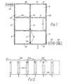
- the curtain wall comprises a frame- like construction of extruded metal sections providing a vertical mullion 2, jamb mullions 4, transoms 6 and top and bottom sills 8, 10 to define a series of rectangular cells 12. Only six cells are shown for simplicity.
- the cells are filled by respective infill panels 14, each of which is double leaved, e.g. as double-glazing, enclosing its own individual air space.
- the spaces are connected together by a series of connections 16, 18 (shown only schematically in Fig. 1) to form one or more flow paths in the interior of the wall, through which air from a pump 20, connected via a filter 22 with the air spaces of the lower cells of the wall, can pass through all the air spaces of the wall to a discharge outlet 24 at the top of the wall.
- adjacent vertical files of cells have the spaces of each file connected in series by the connections 16, and the spaces of the files are connected in parallel by the connections 18.
- the air pump and filter are coupled to an inlet manifold 26 formed by the supporting framework for the panels and running along the bottom of the wall and the air flow exits through a discharge outlet coupled to an outlet manifold 28 similarly formed along the top of the wall.
- Blocking inserts 30 are provided at desired locations in the conduits formed by the framework to control the airflow and prevent it bypassing the air spaces in the panels.
- the horizontal connections 18 serve mainly to equalize pressure between the files.
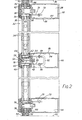
- the panels 32 have inner and outer leaves 34 separated by spacers 36 and are held around their edges by auxiliary members 38 of the framework in an arrangement which may be similar to those described in GB Patents 1459401 and 1496482 and European Patent Application 194779, to which reference can be made for further details.
- the edges of the panels are clamped between box-section main frame members 40 and side limbs 42 of the generally T- or Y-form auxiliary members 38, which are secured to the main members by screws (not shown).
- Flexible sealing gaskets 44 of extruded neoprene are provided between the front and rear edges of each panel and the surfaces of the main frame members and auxiliary members between which these edges of the panel are clamped.
- a main frame member 40 of a transom and an opposed auxiliary frame member 38 are positioned relative to each other by locating plates 46 in opposed recesses 48, 50 respectively in the main and auxiliary members, and are secured together by screws 52 inserted through apertures in the central front recess of the auxiliary members to grip the sides of the recesses 48.
- the members 38, 40 clamp between them the edges of two neighbouring double-glazed panels 32.
- the peripheral spacer 36 extending around the edge of each panel is a U-section channel that takes the place of the seals conventional in such panels.
- a series of apertures 54 in the web of the spacer provide access to the space between the leaves.
- front and rear sealing portions 56, 58 of the flexible sealing gasket 44 Engaging the front and rear leaves of each panel are front and rear sealing portions 56, 58 of the flexible sealing gasket 44.
- the gaskets are described in more detail in my Patent Application (Case A) filed at the same time as this application, which also describes a framework construction employing the same extruded metal sections, and they are each in the form of a continuous loop extending around the periphery of a respective panel, the front and rear sealing portions being linked by an intermediate web 60 that forms a channel around the edge of the panel.
- Each gasket thus encloses the air space in its associated double-glazed panel.
- each panel support plates 62 project at intervals from slots 64 in the transom or bottom sill main frame members in which they are frictionally engaged, and the outer ends of the plates rest on the central rear limbs of the associated auxiliary members.
- the panels bear on the support plates through the gaskets and there are also short panel supports 66 within the gaskets to keep the bottom edges of the panels spaced from the gasket web.
- the panel supports are hollow so as not to block air flow along the gasket under the bottom edge of the panel, and have a U-section shape with inturned flanges on which the edges of the inner and outer leaves 34 rest.
- Connecting tubes 70 lead into the interior of the gaskets at the bottom edge of the lowermost unit at the bottom sill and at the top edge of the uppermost unit at the top sill. In each case the tubes open into the interior of the box sections of the main frame sill members where they have shut-off cocks 72 to isolate the panel air spaces.
- the top and bottom sill box sections thus serve as outlet and inlet manifolds for the pumped air flow.
- connections between successive panels in each vertical file indicated at 16 and 18 in Fig. 1 each comprise two tubes 80 which, in a similar manner to the inlet and outlet connections 70, are mounted in the hollow box-section main frame members through openings in the front walls of the members.
- the front end of each tube extends through an aperture in the web of a respective one of the two gaskets 44, to which it is sealed.
- the rear ends of each adjacent pair of tubes inside the main frame members are joined by a short U-shaped conduit 82 including a non-return valve to ensure that air can only pass from the lower to the upper of the spaces they interconnect.
- each tube 80 has a shut-off cock 88 to allow pressure testing of the units to be performed.
- the curtain wall there are fixed parallel pairs of ribs 92 with a sealing mastic 94 between them.
- the projecting ribs are engaged by an edge gasket 96 mounted between the main and auxiliary frame members in a similar manner to the panel gaskets.
- the edge gasket has front and rear portions of the same sectional form as the panel gaskets for engagement by and sealing with the frame members.
- the integral web 98 between these portions also carries a thicker intermediate portion 100 that has opposite ribbed sealing faces gripped between and engaging with the fixed ribs.
- a connection 104 is provided between each laterally adjacent pair of panels. This comprises a short horizontal tube 106 between the adjacent gasket webs with reduced diameter screwed ends passing through holes in the webs. Nuts 108 threaded onto the screwed ends clamp sealing washers 110 against the edges of the holes.
- While filtering the airflow can remove most foreign particles, it is preferred to reduce the possibility of adhesion of any residual particles or other deposits to the inner surfaces of the panel leaves if they are of a transparent or translucent nature, and it is possible to coat these surfaces with a silicone compound of a type known for making external glass surfaces easier to clean.
- Fig. 4 illustrates a modified supply connection 18, in this case located in a mullion 2. Parts identical to those already described with reference to Figs. 2 and 3 are indicated by the same reference numbers.
- An air supply tube 120 extends through the front web of the mullion box section 40 and is secured in place by locking screws 122. On the threaded outer end of the tube 120 there is screwed a T-piece 124. The oppositely directed arms of the T-piece project through the webs of the adjacent gaskets 44 and have screwed ends to fix and seal them in place using nuts 108 and sealing washers 110.
- An opening 128 at the rear of the box section gives access to the threaded inner end of the tube 120 for connecting it to the air supply circuit.
- connections are provided to establish a circulation of air through the spaces between the panels. If the gas flow is not required for the prevention or removal of condensation it is only necessary in most instances to maintain a positive pressure in a closed volume. Outlet conduits are then not provided or are kept closed and consumption is limited to leakage losses.
- argon can be supplied to the spaces in the panels to give improved sound insulation. It has been shown that argon can give a dB reduction some 5 times greater than that of air. Other gases may be employed to make use of their different physical attributes, e.g. for reducing the transmission of ultra violet light. Pre-dried air may be held in this way, simply to prevent condensation.
- a supply conduit 140 is connected in parallel to a series of panels 142, in each case a non-return valve 144 being provided in the branch line 146 to the particular panel to isolate the panels from each other.
- the spaces within the panels can all be charged to a positive pressure and leakage from one will not draw gas from the others.
- the set-up shown in Fig. 5 also has test valves 148 connected to each branch line downstream of the non-return valve 144 because it illustrates, in fact, a pressure test system for checking the sealing integrity of the individual panels and their gaskets.
- the test valves may be simple core-type inflation valves, such as Schrader (Trade Mark) valves, and they permit a pressure gauge to be connected to each panel interior in turn.
- the flow pattern of Fig. 5 can be achieved using connections such as that shown in Fig. 4, with the rearwardly directed tube 120 containing a Schrader valve 148 and one of T-arms containing a check valve 144.
Landscapes
- Engineering & Computer Science (AREA)
- Architecture (AREA)
- Physics & Mathematics (AREA)
- Electromagnetism (AREA)
- Civil Engineering (AREA)
- Structural Engineering (AREA)
- Load-Bearing And Curtain Walls (AREA)
- Examining Or Testing Airtightness (AREA)
Applications Claiming Priority (4)
| Application Number | Priority Date | Filing Date | Title |
|---|---|---|---|
| GB8601290 | 1986-01-20 | ||
| GB868601290A GB8601290D0 (en) | 1986-01-20 | 1986-01-20 | Wall with multiple layer panelling |
| GB8614573 | 1986-06-10 | ||
| GB868614573A GB8614573D0 (en) | 1986-06-16 | 1986-06-16 | Wall structures |
Publications (2)
| Publication Number | Publication Date |
|---|---|
| EP0238165A2 true EP0238165A2 (de) | 1987-09-23 |
| EP0238165A3 EP0238165A3 (de) | 1989-07-26 |
Family
ID=26290249
Family Applications (1)
| Application Number | Title | Priority Date | Filing Date |
|---|---|---|---|
| EP87300428A Ceased EP0238165A3 (de) | 1986-01-20 | 1987-01-19 | Wand mit mehrschichtigen Paneelen |
Country Status (2)
| Country | Link |
|---|---|
| US (1) | US4756131A (de) |
| EP (1) | EP0238165A3 (de) |
Cited By (3)
| Publication number | Priority date | Publication date | Assignee | Title |
|---|---|---|---|---|
| AT513981A4 (de) * | 2013-04-30 | 2014-09-15 | Gig Holding Gmbh | Einrichtung und Verfahren zur Trocknung zumindest eines Fassadenzwischenraums |
| WO2015164829A1 (en) * | 2014-04-24 | 2015-10-29 | New Jersey Institute Of Technology | Concealed fastener window or curtain wall assemblies |
| CN110306701A (zh) * | 2019-07-10 | 2019-10-08 | 东阳市天杨建筑工程设计有限公司 | 玻璃幕墙 |
Families Citing this family (12)
| Publication number | Priority date | Publication date | Assignee | Title |
|---|---|---|---|---|
| US4942865A (en) * | 1987-08-03 | 1990-07-24 | Pierce Bjorklund Patricia | Compound solar collector building construction |
| SE468606B (sv) * | 1991-09-24 | 1993-02-15 | Nils Gunnar Jansson | Foerfarande jaemte anordning foer saekrande av fasadelement av glas |
| JP2829826B2 (ja) * | 1994-06-17 | 1998-12-02 | ワイケイケイアーキテクチュラルプロダクツ株式会社 | カーテンウォールのパネル材取付構造 |
| WO2001012940A1 (en) | 1999-08-13 | 2001-02-22 | Edgetech I.G., Inc. | Method of fabricating muntin bars for simulated divided lite windows |
| US7743570B2 (en) | 1999-08-13 | 2010-06-29 | Edgetech I.G., Inc. | Method of fabricating muntin bars for simulated divided lite windows |
| RU2321707C2 (ru) * | 2003-09-16 | 2008-04-10 | Реновизион | Опорная рамная конструкция для фасада |
| DE20321415U1 (de) * | 2003-09-16 | 2007-05-31 | Renovision Ingenieurgesellschaft für Fenster und Fassade mbH | Stützrahmenwerk für eine Fassade |
| KR101238120B1 (ko) * | 2007-12-29 | 2013-02-27 | (주)엘지하우시스 | 수평교차환기가 가능한 이중창호 |
| NL2001750C2 (nl) * | 2008-07-03 | 2010-01-05 | M H B B V | Systeem voorzien van panelen, alsmede werkwijze. |
| US8959855B2 (en) * | 2013-05-07 | 2015-02-24 | Elston Window & Wall, Llc | Systems and methods for providing a window wall with flush slab edge covers |
| US20150223410A1 (en) * | 2014-02-09 | 2015-08-13 | Lauren Freeman Jensen | Vacuum Chambered Greenhouse Paneling System |
| US11560713B2 (en) * | 2018-06-24 | 2023-01-24 | Agc Glass Europe | Glazing assembly for a curtain wall glazing system |
Family Cites Families (15)
| Publication number | Priority date | Publication date | Assignee | Title |
|---|---|---|---|---|
| US2062747A (en) * | 1935-10-05 | 1936-12-01 | Pittsburgh Plate Glass Co | Double glazed window |
| US2264176A (en) * | 1940-02-06 | 1941-11-25 | Pittsburgh Plate Glass Co | Multiple glazed unit |
| US2332060A (en) * | 1942-03-20 | 1943-10-19 | Hunter Sash Company Inc | Window |
| US2699580A (en) * | 1950-02-09 | 1955-01-18 | Kirkhill Rubber Company | Canopy seal and process for making the same |
| US2700196A (en) * | 1950-12-28 | 1955-01-25 | Panhard & Levassor | Inflatable weather strip for mounting vehicle windows in frames |
| US2763038A (en) * | 1952-05-13 | 1956-09-18 | Adlake Co | Window structure |
| FR1369790A (fr) * | 1963-09-21 | 1964-08-14 | Dispositif pour le montage et l'assemblage notamment d'éléments de construction tels que panneaux, montants, cloisons ou autres | |
| US3442048A (en) * | 1967-03-17 | 1969-05-06 | Enrique Elias | Ejectable window for a passenger vehicle |
| US3604613A (en) * | 1969-06-25 | 1971-09-14 | Int Paper Co | Side-seam-sealed container |
| GB1459401A (en) * | 1973-01-10 | 1976-12-22 | Stoakes R L | Structural assemblies |
| GB1496482A (en) * | 1973-12-05 | 1977-12-30 | Stoakes R | Structural assemblies |
| DE2931608A1 (de) * | 1979-08-03 | 1981-02-26 | Theodor Straub | Fassadenwand |
| DE2938193C2 (de) * | 1979-09-21 | 1983-05-05 | Bernhard 8581 Bindlach Janke | Vorrichtung zum Abdichten eines Flügels an einem Rahmen bei einem Fenster, einer Tür o.dgl. |
| US4561221A (en) * | 1981-09-17 | 1985-12-31 | Mckee Frederick B | Windows |
| GB8505155D0 (en) * | 1985-02-28 | 1985-04-03 | Stoakes R L | Structural assemblies |
-
1987
- 1987-01-15 US US07/003,415 patent/US4756131A/en not_active Expired - Fee Related
- 1987-01-19 EP EP87300428A patent/EP0238165A3/de not_active Ceased
Cited By (6)
| Publication number | Priority date | Publication date | Assignee | Title |
|---|---|---|---|---|
| AT513981A4 (de) * | 2013-04-30 | 2014-09-15 | Gig Holding Gmbh | Einrichtung und Verfahren zur Trocknung zumindest eines Fassadenzwischenraums |
| AT513981B1 (de) * | 2013-04-30 | 2014-09-15 | Gig Holding Gmbh | Einrichtung und Verfahren zur Trocknung zumindest eines Fassadenzwischenraums |
| WO2015164829A1 (en) * | 2014-04-24 | 2015-10-29 | New Jersey Institute Of Technology | Concealed fastener window or curtain wall assemblies |
| US10202762B2 (en) | 2014-04-24 | 2019-02-12 | New Jersey Institute Of Technology | Concealed fastener window or curtain wall assemblies |
| CN110306701A (zh) * | 2019-07-10 | 2019-10-08 | 东阳市天杨建筑工程设计有限公司 | 玻璃幕墙 |
| CN110306701B (zh) * | 2019-07-10 | 2021-06-22 | 东阳市天杨建筑工程设计有限公司 | 玻璃幕墙 |
Also Published As
| Publication number | Publication date |
|---|---|
| EP0238165A3 (de) | 1989-07-26 |
| US4756131A (en) | 1988-07-12 |
Similar Documents
| Publication | Publication Date | Title |
|---|---|---|
| US4756131A (en) | Wall with multiple layer panelling | |
| US4871379A (en) | Modular, shell-less, air permeator | |
| US5290345A (en) | Refillable gas adsorption bed assembly and counterflow adsorber module | |
| CA2224215A1 (en) | Filter | |
| KR100481774B1 (ko) | 차단개방기 | |
| US5964927A (en) | Adsorption apparatus | |
| JPH10311450A (ja) | 流体制御器用継手 | |
| US10125537B2 (en) | Pressure compensated glass unit | |
| CN103827560A (zh) | 气体供给装置 | |
| US5468283A (en) | Hollow fiber membrane modules with transverse gas flow tailored for improved gas separation | |
| US4202407A (en) | Apparatus for cooling gases from coke plants | |
| US20040103600A1 (en) | Modular bulkhead for sealing passage of cables and pipes in structures of all kinds | |
| US4782636A (en) | Wall structures | |
| US6457717B1 (en) | Method for constructing a fluid barrier | |
| FI84659C (fi) | Vaermevaexlare. | |
| CN109195690B (zh) | 分离膜片模块及组件 | |
| TW200419094A (en) | Fluid control apparatus | |
| US9822581B2 (en) | Pressure compensated glass unit | |
| JP4718037B2 (ja) | パージ用気体分配装置 | |
| JPH0711764Y2 (ja) | 気体分離膜モジュール | |
| CN219272528U (zh) | 一种模块式过滤器以及过滤设备 | |
| RU2032453C1 (ru) | Мембранный аппарат | |
| CA2918471C (en) | Pressure compensated glass unit | |
| JPS61500867A (ja) | 平ガラスサイトゲ−ジ | |
| CA2009818A1 (en) | Guillotine dampers with blade sealing means accommodative of thermal expansion forces |
Legal Events
| Date | Code | Title | Description |
|---|---|---|---|
| PUAI | Public reference made under article 153(3) epc to a published international application that has entered the european phase |
Free format text: ORIGINAL CODE: 0009012 |
|
| AK | Designated contracting states |
Kind code of ref document: A2 Designated state(s): AT BE CH DE ES FR GB IT LI LU NL SE |
|
| PUAL | Search report despatched |
Free format text: ORIGINAL CODE: 0009013 |
|
| AK | Designated contracting states |
Kind code of ref document: A3 Designated state(s): AT BE CH DE ES FR GB IT LI LU NL SE |
|
| 17P | Request for examination filed |
Effective date: 19900123 |
|
| 17Q | First examination report despatched |
Effective date: 19901123 |
|
| STAA | Information on the status of an ep patent application or granted ep patent |
Free format text: STATUS: THE APPLICATION HAS BEEN REFUSED |
|
| 18R | Application refused |
Effective date: 19910720 |