EP0238191A1 - Verfahren und Vorrichtung zum automatischen Setzen von Ziegeln auf eine unterstützende Lage - Google Patents
Verfahren und Vorrichtung zum automatischen Setzen von Ziegeln auf eine unterstützende Lage Download PDFInfo
- Publication number
- EP0238191A1 EP0238191A1 EP87301185A EP87301185A EP0238191A1 EP 0238191 A1 EP0238191 A1 EP 0238191A1 EP 87301185 A EP87301185 A EP 87301185A EP 87301185 A EP87301185 A EP 87301185A EP 0238191 A1 EP0238191 A1 EP 0238191A1
- Authority
- EP
- European Patent Office
- Prior art keywords
- conveyor
- brick
- bricks
- onto
- cassette
- Prior art date
- Legal status (The legal status is an assumption and is not a legal conclusion. Google has not performed a legal analysis and makes no representation as to the accuracy of the status listed.)
- Granted
Links
- 239000011449 brick Substances 0.000 title claims abstract description 188
- 238000000034 method Methods 0.000 title claims abstract description 17
- 230000010006 flight Effects 0.000 claims description 10
- 238000005266 casting Methods 0.000 claims description 5
- 230000033001 locomotion Effects 0.000 claims description 5
- 238000011437 continuous method Methods 0.000 claims 1
- 230000001360 synchronised effect Effects 0.000 claims 1
- 238000004519 manufacturing process Methods 0.000 description 3
- 235000008733 Citrus aurantifolia Nutrition 0.000 description 1
- 235000011941 Tilia x europaea Nutrition 0.000 description 1
- 210000000080 chela (arthropods) Anatomy 0.000 description 1
- 239000004927 clay Substances 0.000 description 1
- 239000004020 conductor Substances 0.000 description 1
- 239000004571 lime Substances 0.000 description 1
- 238000005192 partition Methods 0.000 description 1
- 239000004576 sand Substances 0.000 description 1
- 230000000087 stabilizing effect Effects 0.000 description 1
Images

Classifications
-
- E—FIXED CONSTRUCTIONS
- E04—BUILDING
- E04C—STRUCTURAL ELEMENTS; BUILDING MATERIALS
- E04C2/00—Building elements of relatively thin form for the construction of parts of buildings, e.g. sheet materials, slabs, or panels
- E04C2/02—Building elements of relatively thin form for the construction of parts of buildings, e.g. sheet materials, slabs, or panels characterised by specified materials
- E04C2/04—Building elements of relatively thin form for the construction of parts of buildings, e.g. sheet materials, slabs, or panels characterised by specified materials of concrete or other stone-like material; of asbestos cement; of cement and other mineral fibres
- E04C2/041—Building elements of relatively thin form for the construction of parts of buildings, e.g. sheet materials, slabs, or panels characterised by specified materials of concrete or other stone-like material; of asbestos cement; of cement and other mineral fibres composed of a number of smaller elements, e.g. bricks, also combined with a slab of hardenable material
- E04C2/042—Apparatus for handling the smaller elements or the hardenable material; bricklaying machines for prefabricated panels
Definitions
- the present invention relates to a method and machine for automatic setting of bricks on a supporting layer, as indicated in the preambles of accompanying Claims 1 and 8.
- the object of the present invention is to speed up the making of panels and to simplify the adjustment of the dimensioning of the molds.
- the method is based on a logic-controlled system in which cassettes fed onto the cassette conveyor of the machine are emptied automatically and the bricks set onto the brick conveyor are directed automatically one by one into a turning device and further onto the following brick conveyor, into a row which corresponds to one transverse row in a wall panel, as seen in the manufacturing direction of the panel to be formed, i.e. one vertical row as seen in the using position.
- The-formed ' row is transferred all at one time into a centering device which has separate centering devices for each brick space, in which the position of the brick is centered in relation to the centering devices, and in the transverse direction the distances between the center points of the ! bricks become the same for all bricks.
- a pick-up device which is located above the centering device and has pick-up means for each brick space, grips the bricks, centers them in the longitudinal direction, and lowers them, in a controlled manner, onto the base in the mold in accordance with the programmed setting pattern.
- the mold is an open mold without any compartments or partitions.
- the setting pattern can be, for example, stack bond (a straight pattern of bricks), or 1/2 running bond or 1/3 running bond.
- the logic control of the machine is given the data of the panel, i.e. the length and the height, the dimensions of the openings, and the bond.
- a certain control works only with bricks of a certain size.
- the machine works normally with lime sand and clay bricks 85 x 285 x 16-45.
- certain adjustments must be made in the machine.
- the machine can also be adjusted to work with bricks of 60 mm, 75 mm or any other size, in which case certain devices must be replaced. !
- the machine is driven by electric, pneumatic and hydraulic devices.
- the machine has a compressor and a hydraulic mechanism, and only electric power needs to be introduced into it via a cable or conductor rails.
- the machine drawn by a hydraulic motor, moves above the mold on rails installed on both sides of the mold.
- the travel distance in the machine is measured by a pulse sensor from a measuring wheel which also moves along the rail, together with the machine.
- the control panel of the machine has switches for all of the actuating devices of the machine, and so the machine can also be controlled manually.
- the efficiency of the machine is in the order of one brick site per second.
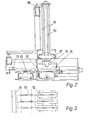
- FIG. 1 the cassette conveyors are indicated by reference numerals 1 and 2 and the crosswise conveyors by numerals 3 and 4.
- a cassette (not shown) filled with bricks is lifted to the beginning of the cassette conveyor 1, on top of the roller chains.
- the conveyor is started and the conveyor rotates until the stepping limit stops it.
- a new cassette is lifted to the beginning of the conveyor and the conveyor is restarted.
- This procedure is continued until the first cassette on the conveyor 1 reaches the end of the conveyor 1 and comes above the crosswise conveyor 3 which, lifted by a pneumatic cylinder, rises and transfers the cassette to the beginning of the cassette conveyor 2.
- the crosswise conveyor 3 is lowered and the cassette is left on the cassette conveyor 2.
- the cassette conveyor 2 conveys the cassette until the stepping limit on the conveyor stops it, whereupon the crosswise conveyor can transfer the next cassette to the beginning of the conveyor 2.
- the filling of the cassette conveyors 1 and 2 continues in this manner until the first cassette has come under the brick take-off device 5 at the end of the cassette conveyor 2, where the limit stops the cassette.
- the first site on the conveyor 1, alongside the brick take-off 5, is, however, left vacant so that the first cassette to be unloaded can, after being emptied, be transferred to it.
- the automatic operation of the machine can be switched on and the machine begins the setting of bricks.
- the brick take-off 5 lifts from the brick cassette being unloaded one layer of bricks at a time, in total 12 bricks, which have been arranged in two rows, the long side of the bricks being parallel to the conveying direction.
- the brick take-off is made up of a suction box fitted in a carriage moving above the cassette being unloaded and the brick conveyor 6 subsequent to it.
- the bottom of the suction box has 24 suction pads, 2 suction pads for each brick.
- the vacuum of the suction pads is produced in the suction box by means of a suction fan through a pipe.
- the suction box is secured to guides which move between the rollers of the carriage and by means of which a pneumatic cylinder lifts and lowers the suction box.
- the carriage is moved on runner rolls in guides in the frame of the brick take-off 5 by a pneumatic cylinder.
- the suction box is lowered on top of the brick layer in the cassette, whereupon the bricks adhere to the suction pads.
- the suction box rises and is transferred to above the brick conveyor 6; where it is lowered.
- the suction ceases, the bricks are detached and the suction box rises to fetch a new layer of bricks from the cassette.
- the suction box rearrives above the brick conveyor it waits there until the bricks have moved away from the beginning of the brick conveyor, and then lowers new bricks onto the conveyor.
- the movement of the bricks on the brick conveyor 6, which is a chain-drawn roller conveyor, is controlled by light cells.
- the bricks travel on the chain conveyor until a light cell located before the next transverse conveyor, which is a belt conveyor 8, stops them if there are bricks on the belt conveyor. If there are no bricks on the belt conveyor, the end 7 of the brick conveyor 6 is raised by pneumatic boxes, and the bricks are transferred from the brick conveyor onto the belt conveyor 8, with the short side of the bricks first. The end 7 of the brick conveyor is relowered and the bricks remain on the belts.
- the bricks are fed into the brick-turning device 9, which is a rotating wheel with 12 compartments at its periphery, into each of which there is fed in turn one brick, the long side first.
- the cylinder of the turning device rotates it 30° and the next brick comes into the next compartment of the turning device. This procedure continues until there is a brick in five compartments of the turning device.
- the brick is in a position turned above a flight conveyor 10.
- the turning of the brick has been included in the setting process for the reason that, during the transfer by means of suction pads, the smooth inner surface of the brick must be upwards in order for the suction pads to adhere to the brick.
- the smooth inner side is the surface which has to be against the bottom of the mold so that the upper surface having the desired pattern will become the upper surface of the-panel.
- the flight conveyor 10 is a closed conveyor driven by a hydraulic motor, having two groups of flights, one on the lower level and the other on the upper level.
- the two parallel chains of the chain track have flights at 100 mm distances. This 100 mm distance corresponds to a brick 85 mm wide, in which case a 15 mm casting clearance is formed between the bricks.
- Each group of flights has preferably 34 flights.
- the conveyor has plastic slide surfaces along which the bricks move, drawn by the flights.
- the brick which has arrived on the conveyor from the turning device remains in the flight and is moved forward.
- Each flight in turn gives, by means of a limit, an order to the turning device to rotate and thereby to lower a new brick onto the flight conveyor.
- the belt conveyor 8, the turning device 9 and the flight conveyor 10 operate synchronically in conjunction with one other.
- the upper level of the flight conveyor is gradually filled.
- a full row of the flight conveyor corresponds to a transverse row of bricks in the wall panel to be formed, i.e. a vertical row of bricks as seen in the position in which the wall panel is used.
- the limit is programmed to stop the turning device for the duration of one or more steps. After the flight conveyor has been filled, it stops when the first flight reaches the limit at the other end of the conveyor.
- the brick row is transferred by means of a pushing device 11 to the centering table 12.
- the pusher is moved on guides located at its both ends by a pneumatic cylinder across the flight conveyor, pushing the bricks as one row onto the centering table.
- a toothed shaft installed across the'pushing path, and a toothed stabilizing wheel has been fitted to travel along it.
- the bricks come between centering springs situated at 100 mm distances, the distance between the center points of the bricks being evened out and set at 100 mm.
- a brick pick-up device which is made up of a row of tongs 13.
- the number of tongs corresponds to the number of bricks fitting in one row to be set, which is thirty-four for 85 mm bricks.
- the jaws 14 of the tongs are closed and opened by a pneumatic cylinder.
- the tong-fastening piece, jaw piece 15, is secured to guides 16, which move in sleeves in the tong-supporting frame 17.
- the lowering movement of the tongs can be limited by means of a stopper at the upper end of the guides 16 and by means of a limiter 18, which is located alongside the guides 16 and is operated by a pneumatically working cylinder.
- the height of the limiter 18 is adjusted by means of screws at its both ends, according to the thickness of the bricks. ;
- the tongs 13 lower over the distance determined by the limiter 18 onto the bricks, and the jaws 14 close around the bricks, at the same time centering them.
- the tongs immediately rise back, whereupon the centering table 12 moves to the side and the limiter of the pincers moves to its rear position.
- those tongs in which there is a brick preferably only every second one lowers into the mold, where the jaws open and the bricks detach from them.
- the remaining tongs with bricks take the bricks into the mold and leave them there.
- All of the tongs can, of course, lower their bricks into the mold simultaneously, but this is less advantageous in terms of the pneumatic mechanism.
- the machine moves forward over the-distance of a predetermined overlap between the lowerings of the tongs.
- the centering table 12 returns to below the tongs 13, and the brick row formed on the flight conveyor 10 during the lowering of the tongs is pushed onto it, while the machine moves to the area of the next row of bricks, and the next row of bricks can be lowered into the mold.
- the machine continues setting in this manner until the panel programmed into it has been completed, and the machine automatically shifts to set the next panel.
- the empty cassettes are removed from the cassette conveyor by manual control, and full cassettes are also loaded by manual control.
Landscapes
- Engineering & Computer Science (AREA)
- Architecture (AREA)
- Civil Engineering (AREA)
- Structural Engineering (AREA)
- Devices For Post-Treatments, Processing, Supply, Discharge, And Other Processes (AREA)
- Waste-Gas Treatment And Other Accessory Devices For Furnaces (AREA)
- Supply And Installment Of Electrical Components (AREA)
- Electrical Discharge Machining, Electrochemical Machining, And Combined Machining (AREA)
- Specific Conveyance Elements (AREA)
- Paper (AREA)
- Sewing Machines And Sewing (AREA)
- Constituent Portions Of Griding Lathes, Driving, Sensing And Control (AREA)
- De-Stacking Of Articles (AREA)
- Nitrogen Condensed Heterocyclic Rings (AREA)
- Furnace Housings, Linings, Walls, And Ceilings (AREA)
Priority Applications (1)
| Application Number | Priority Date | Filing Date | Title |
|---|---|---|---|
| AT87301185T ATE54703T1 (de) | 1986-02-17 | 1987-02-11 | Verfahren und vorrichtung zum automatischen setzen von ziegeln auf eine unterstuetzende lage. |
Applications Claiming Priority (2)
| Application Number | Priority Date | Filing Date | Title |
|---|---|---|---|
| FI860714A FI77176C (fi) | 1986-02-17 | 1986-02-17 | Foerfarande och maskin foer automatisk laeggning av tegel pao ett underlag. |
| FI860714 | 1986-02-17 |
Publications (2)
| Publication Number | Publication Date |
|---|---|
| EP0238191A1 true EP0238191A1 (de) | 1987-09-23 |
| EP0238191B1 EP0238191B1 (de) | 1990-07-18 |
Family
ID=8522184
Family Applications (1)
| Application Number | Title | Priority Date | Filing Date |
|---|---|---|---|
| EP87301185A Expired - Lifetime EP0238191B1 (de) | 1986-02-17 | 1987-02-11 | Verfahren und Vorrichtung zum automatischen Setzen von Ziegeln auf eine unterstützende Lage |
Country Status (6)
| Country | Link |
|---|---|
| EP (1) | EP0238191B1 (de) |
| AT (1) | ATE54703T1 (de) |
| DE (1) | DE3763711D1 (de) |
| DK (1) | DK165582C (de) |
| FI (1) | FI77176C (de) |
| NO (1) | NO162447C (de) |
Citations (3)
| Publication number | Priority date | Publication date | Assignee | Title |
|---|---|---|---|---|
| US3933570A (en) * | 1971-04-09 | 1976-01-20 | The Thomas 1970 Trust | Panel manufacturing machine and method |
| US3990934A (en) * | 1972-11-03 | 1976-11-09 | Lingl Corporation | Method to construct wall panels having openings for doors and windows |
| DE2632765A1 (de) * | 1976-07-21 | 1978-01-26 | Krupp Gmbh | Verfahren zum automatischen herstellen von wandteilen aus kunststeinen und vorrichtung zum durchfuehren des verfahrens |
-
1986
- 1986-02-17 FI FI860714A patent/FI77176C/fi not_active IP Right Cessation
-
1987
- 1987-02-11 AT AT87301185T patent/ATE54703T1/de not_active IP Right Cessation
- 1987-02-11 EP EP87301185A patent/EP0238191B1/de not_active Expired - Lifetime
- 1987-02-11 DE DE8787301185T patent/DE3763711D1/de not_active Expired - Fee Related
- 1987-02-16 NO NO870601A patent/NO162447C/no unknown
- 1987-02-16 DK DK076487A patent/DK165582C/da active
Patent Citations (3)
| Publication number | Priority date | Publication date | Assignee | Title |
|---|---|---|---|---|
| US3933570A (en) * | 1971-04-09 | 1976-01-20 | The Thomas 1970 Trust | Panel manufacturing machine and method |
| US3990934A (en) * | 1972-11-03 | 1976-11-09 | Lingl Corporation | Method to construct wall panels having openings for doors and windows |
| DE2632765A1 (de) * | 1976-07-21 | 1978-01-26 | Krupp Gmbh | Verfahren zum automatischen herstellen von wandteilen aus kunststeinen und vorrichtung zum durchfuehren des verfahrens |
Also Published As
| Publication number | Publication date |
|---|---|
| NO870601D0 (no) | 1987-02-16 |
| FI860714A7 (fi) | 1987-08-18 |
| FI860714A0 (fi) | 1986-02-17 |
| DK76487D0 (da) | 1987-02-16 |
| NO162447C (no) | 1990-01-03 |
| ATE54703T1 (de) | 1990-08-15 |
| DK165582B (da) | 1992-12-21 |
| EP0238191B1 (de) | 1990-07-18 |
| DK76487A (da) | 1987-08-18 |
| FI77176C (fi) | 1989-02-10 |
| FI77176B (fi) | 1988-10-31 |
| NO162447B (no) | 1989-09-25 |
| NO870601L (no) | 1987-08-18 |
| DE3763711D1 (de) | 1990-08-23 |
| DK165582C (da) | 1993-05-03 |
Similar Documents
| Publication | Publication Date | Title |
|---|---|---|
| EP0497051B1 (de) | Vorrichtung zur Palettierung und Formgebung von Lasten | |
| US4541762A (en) | Apparatus for loading and/or unloading machine tools or the like | |
| US3602963A (en) | Apparatus for producing bricks | |
| US4509252A (en) | Method and apparatus for assembling battery components | |
| US3834298A (en) | Brick unloader-stacker apparatus | |
| US3930929A (en) | Apparatus to construct wall panels having openings for doors and windows | |
| US3474917A (en) | Brick machine | |
| US5054994A (en) | Apparatus for stacking unfired brick | |
| US4161368A (en) | Brick blending apparatus | |
| US4338056A (en) | System for loading and unloading a kiln | |
| US3893575A (en) | Brick handling system | |
| US4036350A (en) | Method and apparatus for handling brick for inspection and feeding | |
| US4181212A (en) | Method and apparatus for feeding containers for rod-like articles | |
| US3939994A (en) | Stacking apparatus | |
| KR101771952B1 (ko) | 스틱형 아이스바 스텝 이송장치 | |
| EP0238191B1 (de) | Verfahren und Vorrichtung zum automatischen Setzen von Ziegeln auf eine unterstützende Lage | |
| CN110092176B (zh) | 一种机器人叠板机及其操作方法 | |
| US3894639A (en) | Stacking of bricks | |
| CN218859815U (zh) | 一种托盘搬送堆叠装置 | |
| US5193970A (en) | High speed/high capacity automated workload regulator | |
| CN217478530U (zh) | 一种具有出垛机构的码垛机 | |
| WO2010035153A1 (en) | An apparatus for sorting objects | |
| CN215885155U (zh) | 一种装配式烧结墙板部品的自动转盘填充装置 | |
| EP0151333A1 (de) | Verfahren und Vorrichtung zum Stapeln von Stückgut | |
| CN212196094U (zh) | 一种砌块定量稳定输送装置 |
Legal Events
| Date | Code | Title | Description |
|---|---|---|---|
| PUAI | Public reference made under article 153(3) epc to a published international application that has entered the european phase |
Free format text: ORIGINAL CODE: 0009012 |
|
| AK | Designated contracting states |
Kind code of ref document: A1 Designated state(s): AT BE CH DE ES FR GB GR IT LI NL SE |
|
| 17P | Request for examination filed |
Effective date: 19880322 |
|
| 17Q | First examination report despatched |
Effective date: 19890925 |
|
| GRAA | (expected) grant |
Free format text: ORIGINAL CODE: 0009210 |
|
| AK | Designated contracting states |
Kind code of ref document: B1 Designated state(s): AT BE CH DE ES FR GB GR IT LI NL SE |
|
| PG25 | Lapsed in a contracting state [announced via postgrant information from national office to epo] |
Ref country code: IT Free format text: LAPSE BECAUSE OF FAILURE TO SUBMIT A TRANSLATION OF THE DESCRIPTION OR TO PAY THE FEE WITHIN THE PRE;WARNING: LAPSES OF ITALIAN PATENTS WITH EFFECTIVE DATE BEFORE 2007 MAY HAVE OCCURRED AT ANY TIME BEFORE 2007. THE CORRECT EFFECTIVE DATE MAY BE DIFFERENT FROM THE ONE RECORDED.SCRIBED TIME-LIMIT Effective date: 19900718 Ref country code: AT Effective date: 19900718 Ref country code: FR Effective date: 19900718 Ref country code: BE Effective date: 19900718 Ref country code: CH Effective date: 19900718 Ref country code: NL Effective date: 19900718 Ref country code: LI Effective date: 19900718 Ref country code: GR Free format text: LAPSE BECAUSE OF FAILURE TO SUBMIT A TRANSLATION OF THE DESCRIPTION OR TO PAY THE FEE WITHIN THE PRESCRIBED TIME-LIMIT Effective date: 19900718 |
|
| REF | Corresponds to: |
Ref document number: 54703 Country of ref document: AT Date of ref document: 19900815 Kind code of ref document: T |
|
| REF | Corresponds to: |
Ref document number: 3763711 Country of ref document: DE Date of ref document: 19900823 |
|
| PG25 | Lapsed in a contracting state [announced via postgrant information from national office to epo] |
Ref country code: ES Free format text: LAPSE BECAUSE OF FAILURE TO SUBMIT A TRANSLATION OF THE DESCRIPTION OR TO PAY THE FEE WITHIN THE PRESCRIBED TIME-LIMIT Effective date: 19901029 |
|
| REG | Reference to a national code |
Ref country code: CH Ref legal event code: PL |
|
| EN | Fr: translation not filed | ||
| NLV1 | Nl: lapsed or annulled due to failure to fulfill the requirements of art. 29p and 29m of the patents act | ||
| PG25 | Lapsed in a contracting state [announced via postgrant information from national office to epo] |
Ref country code: GB Effective date: 19910211 |
|
| PLBE | No opposition filed within time limit |
Free format text: ORIGINAL CODE: 0009261 |
|
| STAA | Information on the status of an ep patent application or granted ep patent |
Free format text: STATUS: NO OPPOSITION FILED WITHIN TIME LIMIT |
|
| 26N | No opposition filed | ||
| GBPC | Gb: european patent ceased through non-payment of renewal fee | ||
| EAL | Se: european patent in force in sweden |
Ref document number: 87301185.2 |
|
| PGFP | Annual fee paid to national office [announced via postgrant information from national office to epo] |
Ref country code: DE Payment date: 19980216 Year of fee payment: 12 |
|
| PGFP | Annual fee paid to national office [announced via postgrant information from national office to epo] |
Ref country code: SE Payment date: 19980223 Year of fee payment: 12 |
|
| PG25 | Lapsed in a contracting state [announced via postgrant information from national office to epo] |
Ref country code: SE Free format text: LAPSE BECAUSE OF NON-PAYMENT OF DUE FEES Effective date: 19990212 |
|
| EUG | Se: european patent has lapsed |
Ref document number: 87301185.2 |
|
| PG25 | Lapsed in a contracting state [announced via postgrant information from national office to epo] |
Ref country code: DE Free format text: LAPSE BECAUSE OF NON-PAYMENT OF DUE FEES Effective date: 19991201 |