EP0238354A2 - Béquille latérale de support pour motocyclette - Google Patents
Béquille latérale de support pour motocyclette Download PDFInfo
- Publication number
- EP0238354A2 EP0238354A2 EP87302428A EP87302428A EP0238354A2 EP 0238354 A2 EP0238354 A2 EP 0238354A2 EP 87302428 A EP87302428 A EP 87302428A EP 87302428 A EP87302428 A EP 87302428A EP 0238354 A2 EP0238354 A2 EP 0238354A2
- Authority
- EP
- European Patent Office
- Prior art keywords
- side stand
- leg
- axis
- motorcycle
- swing arm
- Prior art date
- Legal status (The legal status is an assumption and is not a legal conclusion. Google has not performed a legal analysis and makes no representation as to the accuracy of the status listed.)
- Ceased
Links
- 230000007246 mechanism Effects 0.000 abstract description 8
- 239000000428 dust Substances 0.000 description 3
- 230000007935 neutral effect Effects 0.000 description 3
- 239000000463 material Substances 0.000 description 2
- 230000000717 retained effect Effects 0.000 description 2
- 230000001154 acute effect Effects 0.000 description 1
- 238000005452 bending Methods 0.000 description 1
- 238000010276 construction Methods 0.000 description 1
- 239000000356 contaminant Substances 0.000 description 1
- 125000006850 spacer group Chemical group 0.000 description 1
Images








Classifications
-
- B—PERFORMING OPERATIONS; TRANSPORTING
- B62—LAND VEHICLES FOR TRAVELLING OTHERWISE THAN ON RAILS
- B62H—CYCLE STANDS; SUPPORTS OR HOLDERS FOR PARKING OR STORING CYCLES; APPLIANCES PREVENTING OR INDICATING UNAUTHORIZED USE OR THEFT OF CYCLES; LOCKS INTEGRAL WITH CYCLES; DEVICES FOR LEARNING TO RIDE CYCLES
- B62H1/00—Supports or stands forming part of or attached to cycles
- B62H1/02—Articulated stands, e.g. in the shape of hinged arms
Definitions
- This invention relates to a side stand for a motorcycle or like vehicle of a kind which will not stand on its own, unattended.
- Pivoted side stand legs typically are biased to the fully retracted position where they extend substantially rearwardly on the vehicle up adjacent the frame.
- a load bearing position is also provided where the leg extends downwardly and forwardly on the vehicle.
- This intermediate position is also typically a stable position where the side stand leg will remain until either actuated by the riders foot or the weight of the vehicle.
- the intermediate position is commonly arranged such that as the vehicle is tipped towards the side stand, the weight of the vehicle causes the leg to move to the support position. As this is typically the movement of the leg further towards the front of the vehicle, the vehicle normally is moved backwards a small extent in achieving the supported position. From the intermediate position, the operator can use a foot to kick the leg rearwardly on the vehicle until the biasing mechanism draws the leg into the storage position.
- the side stand is provided with an intermediate holding position where the stand does not support the weight of the vehicle.
- a more forward supporting position is also provided, as is a stored position.
- such a device employs some movement of the vehicle relative to the ground once the side stand leg touches the ground, or manual biasing of the side stand leg forwardly to the support position prior to its touching the ground,in order to achieve full support of the vehicle. This can be inconvenient to the operator.
- three positions are again provided with a fairly complicated mechanical system employing a plurality of springs and a moveable fulcrum point.
- the invention provides a side stand of a motorcycle, comprising a side stand leg pivotally mounted about a first axis and having a spring attachment displaced from said first axis; a swing arm pivotally mounted about a second axis above and forwardly on the motorcycle from said first axis, said swing arm extending from said second axis to a first end, the distance from said second axis to said first end being greater than the distance from said second axis to said first axis; and a tension spring coupled with said first end and said spring attachment.
- a linkage swing arm is provided in such a configuration and location that a single spring mechanism employed with the swing arm allows the stand to provide the three required positions, i.e. the retracted storage position, the intermediate non-load bearing position and the supporting position.
- the invention provides a side stand of a motorcycle, comprising a side stand leg pivotally mounted to swing from a rearwardly projecting first position on the motorcycle to a forwardly and downwardly projecting second position on the motorcycle; spring means for resiliently retaining said side stand leg intermediate said first and second positions at a third position with said side stand leg extending forwardly and downwardly on the motorcycle; and a flexible leg fixed to said side stand leg and extending beyond the distal end of said side stand leg.
- a resilient element is arranged at the lower end of the support stand leg which extends beyond the distal end of the leg.
- FIG. 1 through 7 illustrate a first embodiment of the present invention.
- a side stand generally designated 10, is shown attached to a lower body frame pipe F intermediate the front and rear wheels of a motorcycle.
- a mount 12 is shown to be welded to the lower body frame pipe F.
- a side stand leg 20 is pivotally mounted to the mount 12 and thus in turn pivotally mounted relative to the lower body frame pipe F.
- a mounting bolt 24 is shown to extend through the forked mounting plates of the side stand leg 20.
- the mount 12 extends between the forked plates and receives the mounting bolt 24 in pivotal arrangement.
- the side stand leg 20 may pivot about the axis of the mounting bolt 24 extending through point P.
- a stop 18 Associated with the mount 12 is a stop 18.
- the stop 18 is arranged to prevent the side stand leg 20 from pivoting beyond a certain point relative to the vehicle.
- the orientation of the leg 20 when abutting against the stop 18 is illustrated in Figure 1 where the leg 20 extends downwardly and forwardly to its distal end from the pivot. As can be seen in Figure 2, the leg 20 extends outwardly of the vehicle as well.
- An element 16 is associated with the stop 18, providing further constraint on the stand mechanism.
- a fulcrum pin 14 Also located on the mount 12 is a fulcrum pin 14.
- the fulcrum pin 14 is located above and forwardly of the axis of the mounting bolt 24 on the vehicle to define a second axis.
- the swing arm 26 is able to pivot relative to the fulcrum pin 14 and has a hole 28 forming the bearing for the swing arm 26 against the fulcrum pin 14.
- the hole 28 is larger at its lower end to allow assembly of the swing arm 26 onto the fulcrum pin 14 without removal of the pin 14,which has a head at the distal end thereof.
- the swing arm 26 is formed of plate material and includes an elongate arm extending to a first end having an engaging hole 30. The swing arm 26 is able to pivot about the fulcrum pin 14 but is constrained on one side by the element 16 of the stop 18.
- a tensioned coil spring 32 is coupled with the swing arm 26 at the engaging hole 30.
- An attachment point 22 is provided on the side stand leg 20 for receipt of the other end of the tensioned coil spring 32.
- the fulcrum pin 14 is located above and forwardly on the vehicle from the mounting bolt 24.
- the mounting bolt 24, for reference purposes, includes a point P on the axis of the mounting bolt 24.
- a vertical line S is shown extending through point P for reference purposes.
- the front of the motorcyle is to the left of the line S.
- the length of the swing arm 26 as measured between the axis of the fulcrum pin 14 mounting the swing arm 26 and the engaging hole 30 at the first end thereof is greater than the distance between the axis of the fulcrum pin 14 and the axis of the mounting bolt 24.
- the first end of the swing arm 26 extends to a location, under the influence of the spring 32, to between the axis of the mounting bolt 24 and the attachment point 22.
- the location of the element 16 affects the lateral position of the first end of the swing arm 26 relative to the location of the side stand leg 20 in certain orientations thereof.
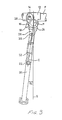
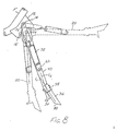
- Figures 1 and 3 through 7 illustrate the stand in a variety of positions.
- Figure 1 illustrates the position of the side stand leg 20 when in the load bearing position supporting the vehicle. In this position, the side stand leg 20 forms an angle ⁇ 1 with regard to the reference line S.
- the swing arm 26 is retained by the action of the fulcrum pin 14 and the element 16 on the stop 18 to the configuration illustrated. In this configuration, the first end of the swing arm 26 extends to the right of a line A extending between point 20 and the center of the attachment point 22. At this point, the first end of the swing arm 26 is located rearwardly of the vehicle from the line A.
- Figure 3 illustrates an intermediate position of the side stand leg 20. This intermediate position is established without the weight of the vehicle on the side stand leg 20 but with the leg extended.
- the reference lines A and B overlie one another to form a reference line C extending through the point P, the center of the engaging hole 30 and the center of the attachment point 22.
- the element 16 of the stop 18 continues to retain the swing arm 26 at a pre-determined angle, dictating the orientation of the line C.
- the leg 20 forms an angle ⁇ 2 with the reference line S.
- the spring 32 aligned with the pivot axis of the mounting bolt 24, no torque is experienced about that pivot axis. Consequently, a stable or neutral position is obtained in this orientation.
- the side stand leg 20 extends downwardly and to the left.
- the reaction force of the ground and the weight of the vehicle creates a clockwise moment to advance the side stand leg 20 (or to back up the vehicle) into the orientation of Figure 1 with the leg extending more forwardly on the vehicle than in the non-bearing condition.
- the forward inclination of the depending side stand leg 20 in the non-bearing position is small in order than forward movement of the vehicle would pivot the stand rearwardly if the distal end thereof contacted the ground.
- the orientation of the side stand leg 20 as illustrated in Figure 5 is an unstable position with the spring 32 tensioned to the maximum. As reference lines A and B coincide to form reference line D, there is no moment generated by the tension in the spring 32. However, any variation in the angle ⁇ 3 would generate a moment and result in movement of the side stand leg 20 in one direction or the other. In the circumstance when the side stand leg 20 has been extended, use of the riders foot to move the side stand leg 20 into the stored position requires overcoming clockwise moment imposed by the spring 32 on the side stand leg 20 between the angles ⁇ 2 and ⁇ 3. Once ⁇ 3 is exceeded, the side stand leg 20 will pivot upwardly to the stored position. Operation to lower the stand from the stored position to the extended position would operate in reverse of the foregoing progression. Thus, depending on which way the side stand leg 20 rotates, it will either rotate through a position as shown in Figure 4 or through a position as shown in Figure 6 as it progresses toward either of the two stable positions to either side of the unstable position illustrated in Figure 5.
- the orientation of the side stand leg 20 as illustrated in Figure 7 is the stored position. In this orientation, the side stand leg 20 extends rearwardly from the mounting bolt 24 on the vehicle.
- the fulcrum pin 14 being above the mounting bolt 24, the spring 32 provides a counter clockwise moment which retains the leg in place.
- the stand is easy to manipulate and does not impact very hard in encountering stops. Naturally, moving the leg toward the position as illustrated in Figure 1 from the position illustrated in Figure 7 passes through the foregoing conditions and operations in reverse.
- the orientation of the simple linking of the swing arm 26 and the spring 32 in cooperation with the leg 20 and the stop 18 provides for a multi-position side stand mechanism convenient to operate and use. Further, a minimum number of parts are employed for ease of construction. The parts are also considered durable with the main load on the side stand leg 20 being through a secure pivot.
- a resilient element extending beyond the bottom 34 of the side stand leg 20.
- the resilient element comprises a ground contact rubber 36 connected by means of a bracket 38 to the lower end of the leg 20.
- the ground contact rubber 36 is aligned along an axis L1 which is inclined relative to the longitudinal axis L2 of the side stand leg 20.
- the distal end of the ground contact rubber 36 is located rearwardly of the end or contact face 34 of the side stand leg 20 when the leg is extended downwardly.
- an inclined face 40 faces forward at the distal end of the ground contact rubber 36.
- the axis line L1 extends forwardly with respect to the vertical reference line S.
- the distal tip of the ground contact rubber 36 is also found to be forwardly on the motorcycle relative to the vertical reference line S.
- the reference line S extends vertically from the center of the mounting bolt 24.
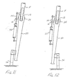
- the ground contact rubber 36 When the body of the motorcycle is held upright and the end of the ground contact rubber 36 is not pressed against the ground G, the ground contact rubber 36 extends downwardly as illustrated in Figure 9. When the body of the vehicle is tilted toward the side stand, the ground contact rubber 36 is pressed against the ground G, such that the ground contact rubber 36 bends to face the rear as shown in Figure 10. Because of the inclined face 40, the angle of the axis L1 relative to the ground (a1) may be smaller and still insure that the ground contact rubber 36 will be bent to the rear when loaded.
- the ground contact rubber 36 when contacting the ground G, will create a friction force which will tend to retain the distal end of the ground contact rubber 36 at the location where it contacts the ground G.
- the friction force retains the distal end of the ground contact rubber 36 in place and the bending of the rubber 36 will cause the leg 20 to pivot about the mounting bolt 24 in a clockwise direction, as seen in Figures 9 and 10, toward the front of the vehicle.
- the leg 20 which moves forwardly relative to the ground rather than the vehicle moving rearwardly relative to the ground in order to achieve the appropriate angle on the stand for supporting the vehicle.
- an inverted U shaped mount 42 is employed with a leg 20 positioned within the mount 42.
- a pin 44 extends between the sides of the inverted U shaped mount 42 to pivotally mount the leg 20.
- the pin 44 includes a large head 46 which operates as a stop for the swing arm 48.
- the swing arm 48 is configured to extend around the head 46 for appropriate maximum rotation of the swing arm 48 so as to operate as in the prior embodiments.
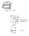
- Figures 15 and 16 discloses a mechanism substantially like that of Figures 13 and 14. Greater attention is directed to the mounting arrangement where the bracket 42 is again shaped in an inverted U, including legs 50 and 52. The pin 44 is shown to be retained by a nut 54. The leg 20 extends up to a mounting portion 56 accommodating a bearing 58 and a spacer 60. Dust seals 62 protect the bearing.
- the distances d1, d2 and d3 as illustrated in Figure 16 accommodate the components without overly extending the components laterally outwardly on the vehicle and without causing contact and rubbing where inappropriate.
- the leg 20 is shown to be welded to a cylindrical member 64 to define the upper pivotal portion thereof.
- the bearing 58 includes a flange 66 at one end thereof along with a dust seal 62 at the other. This helps retain material from the bearing without requiring two dust seals 62.
- the inverted U configuration also aids in allowing contaminants to fall from the area of the bearing.
- bracket 12 is shown to be welded to a doubling plate 68 in turn welded to the frame F.
- the swing arm 70 is formed with a linear shape and extends to an engaging lug 72 having a projection 74 for engaging the head 46 of the pivot shaft. In this way, limitation on the movement of the swing plate is again achieved.
Landscapes
- Engineering & Computer Science (AREA)
- Mechanical Engineering (AREA)
- Motorcycle And Bicycle Frame (AREA)
- Vehicle Cleaning, Maintenance, Repair, Refitting, And Outriggers (AREA)
Applications Claiming Priority (4)
| Application Number | Priority Date | Filing Date | Title |
|---|---|---|---|
| JP3994886U JPS62152888U (fr) | 1986-03-20 | 1986-03-20 | |
| JP39948/86 | 1986-03-20 | ||
| JP181143/86 | 1986-11-27 | ||
| JP18114386U JPS6387196U (fr) | 1986-11-27 | 1986-11-27 |
Publications (2)
| Publication Number | Publication Date |
|---|---|
| EP0238354A2 true EP0238354A2 (fr) | 1987-09-23 |
| EP0238354A3 EP0238354A3 (fr) | 1988-07-20 |
Family
ID=26379348
Family Applications (1)
| Application Number | Title | Priority Date | Filing Date |
|---|---|---|---|
| EP87302428A Ceased EP0238354A3 (fr) | 1986-03-20 | 1987-03-20 | Béquille latérale de support pour motocyclette |
Country Status (2)
| Country | Link |
|---|---|
| EP (1) | EP0238354A3 (fr) |
| AU (1) | AU588983B2 (fr) |
Cited By (2)
| Publication number | Priority date | Publication date | Assignee | Title |
|---|---|---|---|---|
| US6561467B1 (en) * | 2000-09-15 | 2003-05-13 | Amir Farsio | Quick-release variable position slidable scooter jackstand |
| US7631885B2 (en) | 2007-04-16 | 2009-12-15 | Harley-Davidson Motor Company Group, LLC | Intelligent interlock for a motorcycle stand |
Family Cites Families (2)
| Publication number | Priority date | Publication date | Assignee | Title |
|---|---|---|---|---|
| FR622471A (fr) * | 1926-10-02 | 1927-05-31 | Fu R Feinmechanik Vormals Jett | Support pour cycle |
| AU465374B2 (en) * | 1973-11-16 | 1975-09-25 | Honda Giken Kogyo Kabushiki Kaisha | Side-stand for motorcycle |
-
1987
- 1987-03-20 EP EP87302428A patent/EP0238354A3/fr not_active Ceased
- 1987-03-20 AU AU70457/87A patent/AU588983B2/en not_active Ceased
Cited By (2)
| Publication number | Priority date | Publication date | Assignee | Title |
|---|---|---|---|---|
| US6561467B1 (en) * | 2000-09-15 | 2003-05-13 | Amir Farsio | Quick-release variable position slidable scooter jackstand |
| US7631885B2 (en) | 2007-04-16 | 2009-12-15 | Harley-Davidson Motor Company Group, LLC | Intelligent interlock for a motorcycle stand |
Also Published As
| Publication number | Publication date |
|---|---|
| AU7045787A (en) | 1987-09-24 |
| EP0238354A3 (fr) | 1988-07-20 |
| AU588983B2 (en) | 1989-09-28 |
Similar Documents
| Publication | Publication Date | Title |
|---|---|---|
| EP0845408B1 (fr) | Dérailleur arrière avec dispositif amortisseur | |
| US4939950A (en) | Handlebar assembly for cycles | |
| US5191675A (en) | Caster mechanism for carriage | |
| JP2996660B2 (ja) | 自転車用ディレイラ― | |
| US4726252A (en) | Spring-back bike lever | |
| WO2000063892B1 (fr) | Verrou d'inertie pour unite de disque mobile | |
| EP0238354A2 (fr) | Béquille latérale de support pour motocyclette | |
| US6472623B1 (en) | Turn signal cancel device | |
| JPH0858661A (ja) | 自転車用ブレーキ装置 | |
| GB2338774A (en) | Vehicle control pedal assemblies eg for drive-by-wire systems | |
| JP3317235B2 (ja) | チルトキャブの支持ステー | |
| US5463409A (en) | Tracker balls | |
| US3307420A (en) | Steering mechanism | |
| JPH0347835Y2 (fr) | ||
| JPS6225994Y2 (fr) | ||
| JPH0444435Y2 (fr) | ||
| JP3354835B2 (ja) | 車両用フットレスト装置 | |
| JPH0132481Y2 (fr) | ||
| JP3128587B2 (ja) | チルトステアリング装置 | |
| KR870003987Y1 (ko) | 산업용 용접로보트의 용접토오치 클램프 | |
| JP3607938B2 (ja) | 田植機のサイドマーカ | |
| JP3729709B2 (ja) | コラムシフト装置の衝撃吸収機構 | |
| JPH076235Y2 (ja) | シールドジャッキの保持装置 | |
| KR200227356Y1 (ko) | 페달용스프링설치구조 | |
| JPH0336133Y2 (fr) |
Legal Events
| Date | Code | Title | Description |
|---|---|---|---|
| PUAI | Public reference made under article 153(3) epc to a published international application that has entered the european phase |
Free format text: ORIGINAL CODE: 0009012 |
|
| AK | Designated contracting states |
Kind code of ref document: A2 Designated state(s): DE FR GB IT |
|
| PUAL | Search report despatched |
Free format text: ORIGINAL CODE: 0009013 |
|
| AK | Designated contracting states |
Kind code of ref document: A3 Designated state(s): DE FR GB IT |
|
| 17P | Request for examination filed |
Effective date: 19890102 |
|
| 17Q | First examination report despatched |
Effective date: 19900129 |
|
| STAA | Information on the status of an ep patent application or granted ep patent |
Free format text: STATUS: THE APPLICATION HAS BEEN REFUSED |
|
| 18R | Application refused |
Effective date: 19910228 |
|
| RIN1 | Information on inventor provided before grant (corrected) |
Inventor name: FUNAYAMA, YOSHIHIRO Inventor name: SANADA, KATSUIKI Inventor name: IIJIMA, SATOSHI Inventor name: SAKATA, MASAYASU |