EP0238457A2 - Structure réticulaire composée de sections élémentaires pour la décoration et l'éclairage intérieurs - Google Patents
Structure réticulaire composée de sections élémentaires pour la décoration et l'éclairage intérieurs Download PDFInfo
- Publication number
- EP0238457A2 EP0238457A2 EP87830106A EP87830106A EP0238457A2 EP 0238457 A2 EP0238457 A2 EP 0238457A2 EP 87830106 A EP87830106 A EP 87830106A EP 87830106 A EP87830106 A EP 87830106A EP 0238457 A2 EP0238457 A2 EP 0238457A2
- Authority
- EP
- European Patent Office
- Prior art keywords
- shapes
- elements
- reticular
- structure according
- sleeves
- Prior art date
- Legal status (The legal status is an assumption and is not a legal conclusion. Google has not performed a legal analysis and makes no representation as to the accuracy of the status listed.)
- Withdrawn
Links
Images



Classifications
-
- E—FIXED CONSTRUCTIONS
- E04—BUILDING
- E04C—STRUCTURAL ELEMENTS; BUILDING MATERIALS
- E04C3/00—Structural elongated elements designed for load-supporting
- E04C3/30—Columns; Pillars; Struts
- E04C3/32—Columns; Pillars; Struts of metal
-
- E—FIXED CONSTRUCTIONS
- E04—BUILDING
- E04C—STRUCTURAL ELEMENTS; BUILDING MATERIALS
- E04C3/00—Structural elongated elements designed for load-supporting
- E04C3/02—Joists; Girders, trusses, or trusslike structures, e.g. prefabricated; Lintels; Transoms; Braces
- E04C3/04—Joists; Girders, trusses, or trusslike structures, e.g. prefabricated; Lintels; Transoms; Braces of metal
- E04C3/08—Joists; Girders, trusses, or trusslike structures, e.g. prefabricated; Lintels; Transoms; Braces of metal with apertured web, e.g. with a web consisting of bar-like components; Honeycomb girders
-
- F—MECHANICAL ENGINEERING; LIGHTING; HEATING; WEAPONS; BLASTING
- F21—LIGHTING
- F21S—NON-PORTABLE LIGHTING DEVICES; SYSTEMS THEREOF; VEHICLE LIGHTING DEVICES SPECIALLY ADAPTED FOR VEHICLE EXTERIORS
- F21S2/00—Systems of lighting devices, not provided for in main groups F21S4/00 - F21S10/00 or F21S19/00, e.g. of modular construction
-
- E—FIXED CONSTRUCTIONS
- E04—BUILDING
- E04C—STRUCTURAL ELEMENTS; BUILDING MATERIALS
- E04C3/00—Structural elongated elements designed for load-supporting
- E04C3/02—Joists; Girders, trusses, or trusslike structures, e.g. prefabricated; Lintels; Transoms; Braces
- E04C3/04—Joists; Girders, trusses, or trusslike structures, e.g. prefabricated; Lintels; Transoms; Braces of metal
- E04C2003/0486—Truss like structures composed of separate truss elements
-
- E—FIXED CONSTRUCTIONS
- E04—BUILDING
- E04C—STRUCTURAL ELEMENTS; BUILDING MATERIALS
- E04C3/00—Structural elongated elements designed for load-supporting
- E04C3/02—Joists; Girders, trusses, or trusslike structures, e.g. prefabricated; Lintels; Transoms; Braces
- E04C3/04—Joists; Girders, trusses, or trusslike structures, e.g. prefabricated; Lintels; Transoms; Braces of metal
- E04C2003/0486—Truss like structures composed of separate truss elements
- E04C2003/0495—Truss like structures composed of separate truss elements the truss elements being located in several non-parallel surfaces
Definitions
- the invention refers to a reticular structure made up of sectional elements for supporting lighting means for interior decoration and other. Substantially, it comprises straight reticular modular elements, with three longitudinal structural shapes disposed according to a triangular configuration in the transverse section and reticular connections only on two of the three interspaces between said shapes in order to allow the piling-up of more elements one inside the other and said shapes having slightly projecting ends; sleeves are provided for connecting abutting ends of shapes of adjacent elements, whith clamping means, as well as a crosspiece equipped with said sleeves for its engagement with the ends of the shapes on the side lacking in reticular connections. Auxiliary components are applicable at the ends of said shapes being supplied with appendixes corresponding to said ends for the connection through said sleeves.
- Angular modular elements are as well provided with three arcuate curved shapes, having ends suitable to correspond to those of the straight elements, and with reticular connections provided as well on only two of the interspaces between said three shapes.
- the shapes are advantageously of circular cross-section, and the.sleeves are cylindrical and have three threaded holes for blocking screws and for the connection with said crosspiece.
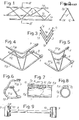
- one of the basic componentsof the structure is represented by reticular modular elements of 600, 900 and 1200 mm in length, for example, which are characteristically formed with a triangular development of their section, wherein, in correspondence of the angles, three longitudinal shapes lA, 1B, 1C are provided having circular cross-sections like metal rods which are connected between them along two of the mutual spacings through reticular connections 3 developed like inclined wind-bracings; in particular, these reticular connections are developed between the two shapes 1A, 1B and between the two shapes 1B, 1C, whereas they are not present in the spacing between 1A and 1C.
- the reticular modular elements may be piled up as shown in particular in Fig.
- the ends of the shapes 1A, 1B, 1C are at least slightly projecting in respect to the reticular connections, in such a way that, on said ends, sleeves 5 may be fitted (see also Figs. 7 to 9) which are of use for the connection of adjacent reticular elements, and of other components, with the straight reticular elements.
- the connecting sleeves 5 may be practically developed with a longitudinal through hole 5A intended to receive the ends of the shapes 1A, 1B, 1C and of equivalent ones; on a projecting portion 5B of the sleeve 5 transverse threaded through holes, indicated by 7A, 7B (external) and by 7C (internal), are formed.
- a tension rod 9 may be fixedly engaged connecting the two end sleeves 5, so that the corresponding holes 5A of these two sleeves can result exactly spaced apart at the same distance as the shapes 1A, 1B, 1C, provided that the longitudinal reticular elements have an equilateral triangular development and, in such a way that the distance between the holes 5A of the two sleeves engaged by the tension rod 9 corresponds to the distance between the two shapes 1A, 1C of the straight reticular modular elements.
- the screws indicated by 10 and able to be engaged with the holes 7A, 7B and possibly 7C may be point-like developed in order to be tightly fitted into the ends of shapes 1A, 1B, 1C and into the appendixes provided in other components of the structure.
- the unit depending on the tension rod 9 represents a crosspiece that may be applied to the ends of the shapes 1A, 1C in order to complete, at the ends of the straight reticular elements, the triangular section and to allow the coupling with other components of the structure, by utilizing, in correspondence of the ends of the shape 1B, an isolated sleeve 5.
- Figs. 4 and 5 show two angular elements, also developed with three shapes similar to those 1A, 1B, 1C, but being bent or curved so as to actually form angular elements; these shapes are indicated by 11A, 11B and 11C and, respectively, by 111A, 111B and 111C, the shape 111C being, in this case, limited to a short angle to which a sleeve 5, which is connected to a tension rod 9, may be engaged.
- the use of the crosspieces made up of the tension rods 9 with the sleeves 5 engaged at their ends, is if use both for the connection with adjacent elements and for the mutual stiffening between shapes like those indicated by 1A, 1C, respectively 11A, 11C, respectively 111A and 111C.
- Fig. 6 shows a terminal element 13 to be applied to the above described reticular elements, which is developed with an arcuate shape 15A able to receive at its ends two sleeves 5 which may be or may be not connected through a tension rod 9; in the middle of the arcuate stretch of the shape 15A a shape 15B is engaged, symmetrically disposed relative to the shape 15A and so bent as to form an end element being triangularly disposed in respect to the ends of the arcuate shape 15A, for the connection with the reticular elements described above.
- the terminal 13 can be utilized both as a vertical upper terminal and as a horizontal terminal, as well as a terminal for elements to be cantilever mounted.
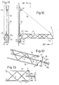
- a straight reticular element indicated by 21, by means of two terminals 13A and 13B, the latter being of a special type with a bridge 13C so developed as to make up a transverse articulation to be engaged with an articulating support fixed to a plate 23 to be mounted on a wall.
- This plate 23 is provided in particular, as a support and articulation means for the bridge 13C, of a pair of discoid members 25 that may be tightened by a screw 26 going through axial holes of said discoid members, the latter being provided with impressions of semi-circular and straight cross-section and disposed like two chords corresponding to each other so as to form a seat for the articulation bridge 13C.
- the support formed by the two discoid members 25 is able to be oriented both about the axis of the screw 26 and about the axis of the impressions which are orthogonal to a plane passing through the axis of the screw26, accordingly, the bracket 21 is realized in order to constitute a punctiform articulation.
- the bracket 21 is also supported by a cable 30 which is entrained over a pulley 32 provided at the upper end of the plate 23, the cable being anchored at a suitable fastening means 34, for example, through a bitt.
- Figs. 12 and 13 show an end component made up of a triangular plate 36 with three appendixes 37 being fully similar to the ends of the shapes 1A, 1B, 1C or 11A, 11B, 11C or 111A, 111B, 111C, to be received inside the sleeves 5 and fastened by the screws 10 of the same sleeves 5.
- the triangular plate 36 has a hub 36A with a threaded through hole for a screw pin 38 provided at its outer end, that is, opposite to the appendixes 37, with an expansion 38A which serves for leaning against a wall.
- a plate terminal 36 is intended to form a support and a stop for a reticular structure formed by horizontally located straight reticular elements, in order to block such structure against axial movements which may occur inside the residual space relative to opposite walls, between which this linear structure may be developed.
- Figs. 14, 15 and 16 show two plates 40 and 42 respectively, the first 40 having slots 40A that provide for the hooking of suspension means of a structure to a ceiling or other; the plate 42, mostly metallic, may be provided with holes for wall mounting.
- Both the end plates 40 and 42 of triangular development have appendixes 44 which, like those indicated by 37, serve for their fastening at the ends of the shapes like those indicated by 1A, 1B, 1C or equivalent, by utilizing the sleeves 5 possibly together with a crosspiece 9.
- Figs. 17 and 18 show a base 48 that may be made of drawn sheet having circular development (according to the drawing) and appendixes 49 capable of. being engaged in the sleeves 5 for connecting the base 48 to a reticular structure formed by the above mentioned elements.
- the appendixes 49 may be fastened by welding, respectively by screw-clamping means to allow an easier and less bulky packing.
- FIG. 19 to 22 Another type of base for reticular structures as above described, is illustrated in Figs. 19 to 22.
- This base is made up of a central laminar member 50, that may have circular shape, and of three short bars 52 which can be engaged radially thereto as they are provided with slit seats for housing the edge of said laminar member; said short bars 52 have holes 56 which, upon the assembly of the three bars on the laminar member 50, are able to reach a mutual position corresponding to that of the structural shapes disposed along the corners, with a triangular positioning in the section of the above described reticular elements; accordingly, a reticular structure may be fitted on this base to support it, the short bars being kept, in turn, by the shapes having their ends housed into the holes 56 and possibly screw-blocked therein and by the misalignment that said short bars form with the central laminar member 50.
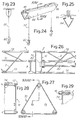
- a horizontal reticular structure as above described may be suspended through the intervention of the terminal plates like those 40 respectively through the engagement to the shapes 1A or 1B or 1C or others, by means of spring-clip members 60 (see Figs. 23 and 24) that are supported by filiform elements 62 which can be engaged on hooks of the ceiling respectively on shapes like that indicated by 64 which can be engaged with brackets 66 previously fastened to the ceiling.
- a ceiling light 66 can be engaged with two shapes like those indicated by 1A and 1C, through blocks 68 U-developed and apt to be hooked to the shapes 1A, 1C owing to an elasticity obtainable both with the ceiling light and, with the unconnected shapes just like those indicated by 1A, 1C.
- box- like elements may be also provided like those indicated by 70 in Figs. 26 to 33, being supplied with appendixes 72 similar to those already described for other components, for their engagement at the ends of the shapes through the aid of sleeves 5.
- a lid 74 may be applied to the box element 70 to close it and so as to exhibit appendixes 76 similar to those indicated by 72 and to those previously described, for the continuation of the structure, again connectable with sleeves 5.
- the placing may be arranged of tubular lamps - like those indicated by 80 and carried by terminals 82 at least partially applied in the box 70 - or of the PL type.
- the boxes 70 may be interposed between straight reticular elements being horizontally disposed or even vertically disposed like posts or torch holders.
- Fig. 36 there are shown utilizations of boxes 70 between two vertical reticular elements 84 and 86 applied between adjacent boxes and the one indicated by 86 on a base like that indicated by 48 or other equivalent; the two boxes 70 illustrated therein may actually house a lamp 80 vertically disposed.
- a lamp 80 may be shielded by laminar and semi-transparent shields 88 acting like diffusers, which may be developed either on three sides or even only on two sides like a dihedral as shown in the drawing, the shields 88 being able to engage the shapes like those indicated by 1A, 1B and 1B, 1C so as to permit a directional light projection in one direction, and a diffusion of the light through the diffusing shields in other directions.
- laminar and semi-transparent shields 88 acting like diffusers, which may be developed either on three sides or even only on two sides like a dihedral as shown in the drawing, the shields 88 being able to engage the shapes like those indicated by 1A, 1B and 1B, 1C so as to permit a directional light projection in one direction, and a diffusion of the light through the diffusing shields in other directions.
- a structure similar to the one above described and relative to a torch holder may be utilized with a reticular element 90 (see Figs. 38 and 39), which is made to terminate with ball or similar supports, indicated by 92, for a cup 94 holding a suitable upwardly directed projector also capable of being oriented because it can be made to rest on three terminals 92 of rubber or other material providing a minimum friction sufficient to allow for the desired positioning of the component 94.
- reticular elements may be utilized to form the most varied combinations to meet the user's requirements, both for decorative effects and for supporting lighting means and for any other use. It is possible to realize, for example, a U structure that can be cantilever mounted, respectively a square structure to be suspended, for example, in the middle of the ceiling. Any other structure may be possibly conceived stemming from a ceiling, from a wall, or leaning on a floor or combined to make up a floor-, wall- and ceiling-connection.
Landscapes
- Engineering & Computer Science (AREA)
- Architecture (AREA)
- Civil Engineering (AREA)
- Structural Engineering (AREA)
- General Engineering & Computer Science (AREA)
- Non-Portable Lighting Devices Or Systems Thereof (AREA)
Applications Claiming Priority (2)
| Application Number | Priority Date | Filing Date | Title |
|---|---|---|---|
| IT09356/86A IT1204040B (it) | 1986-03-21 | 1986-03-21 | Struttura reticolare ad elementi componibili per arredamento e illuminazione |
| IT935686 | 1986-03-21 |
Publications (2)
| Publication Number | Publication Date |
|---|---|
| EP0238457A2 true EP0238457A2 (fr) | 1987-09-23 |
| EP0238457A3 EP0238457A3 (en) | 1989-06-07 |
Family
ID=11128913
Family Applications (1)
| Application Number | Title | Priority Date | Filing Date |
|---|---|---|---|
| EP87830106A Withdrawn EP0238457A3 (en) | 1986-03-21 | 1987-03-20 | Reticular structure made up of sectional elements for interior decoration and lighting |
Country Status (2)
| Country | Link |
|---|---|
| EP (1) | EP0238457A3 (fr) |
| IT (1) | IT1204040B (fr) |
Cited By (8)
| Publication number | Priority date | Publication date | Assignee | Title |
|---|---|---|---|---|
| EP0331317A3 (en) * | 1988-02-27 | 1990-06-13 | James Alexander Slater | Lighting support |
| EP0398068A1 (fr) * | 1989-05-19 | 1990-11-22 | Christoph Kaesbohrer | Assemblage pour poutres |
| DE9010562U1 (de) * | 1990-07-13 | 1991-11-14 | Xylo Buchstaben Rudolf Prien GmbH, 8000 München | Raumfachwerk |
| USD357091S (en) | 1993-05-07 | 1995-04-04 | Spi Lighting, Inc. | Bracket for a suspended lighting fixture system |
| EP0614040A3 (en) * | 1993-03-05 | 1996-08-21 | Giampaolo Targetti | Sectional network structure for lighting. |
| US5551199A (en) * | 1993-11-08 | 1996-09-03 | Hayes; Jerry R. | Box truss for lights |
| GB2444327A (en) * | 2006-12-01 | 2008-06-04 | Conder Structures Ltd | Multi-part column assembly for a building structure |
| DE102011009711A1 (de) | 2011-01-29 | 2012-08-02 | Holger Drewes | Beleuchtungsvorrichtung |
Family Cites Families (8)
| Publication number | Priority date | Publication date | Assignee | Title |
|---|---|---|---|---|
| DE266714C (fr) * | ||||
| US2098343A (en) * | 1936-11-18 | 1937-11-09 | Lawton Lon | Skeleton pole |
| US3193060A (en) * | 1962-05-29 | 1965-07-06 | Park Wallace Sidney | Structural bracing member |
| US3319059A (en) * | 1964-12-30 | 1967-05-09 | Miller Co | Sectional lighting fixture |
| US3670471A (en) * | 1970-05-12 | 1972-06-20 | All Products Co | Sectional tower structure |
| SE354497B (fr) * | 1972-05-09 | 1973-03-12 | Wikstrand & Berg Wibe Ab | |
| DE2423274C2 (de) * | 1974-05-14 | 1982-05-06 | Julian Borisovič Moskva Ajzenberg | Lichtleiter-Raumleuchte |
| US4633624A (en) * | 1984-09-18 | 1987-01-06 | Targetti Sankey S.P.A. | Assembly of components trestle type for outside fittings |
-
1986
- 1986-03-21 IT IT09356/86A patent/IT1204040B/it active
-
1987
- 1987-03-20 EP EP87830106A patent/EP0238457A3/en not_active Withdrawn
Cited By (11)
| Publication number | Priority date | Publication date | Assignee | Title |
|---|---|---|---|---|
| EP0331317A3 (en) * | 1988-02-27 | 1990-06-13 | James Alexander Slater | Lighting support |
| EP0398068A1 (fr) * | 1989-05-19 | 1990-11-22 | Christoph Kaesbohrer | Assemblage pour poutres |
| WO1990014522A1 (fr) * | 1989-05-19 | 1990-11-29 | Christoph Kaesbohrer | Assemblage de poutres |
| DE9010562U1 (de) * | 1990-07-13 | 1991-11-14 | Xylo Buchstaben Rudolf Prien GmbH, 8000 München | Raumfachwerk |
| EP0614040A3 (en) * | 1993-03-05 | 1996-08-21 | Giampaolo Targetti | Sectional network structure for lighting. |
| USD357091S (en) | 1993-05-07 | 1995-04-04 | Spi Lighting, Inc. | Bracket for a suspended lighting fixture system |
| US5551199A (en) * | 1993-11-08 | 1996-09-03 | Hayes; Jerry R. | Box truss for lights |
| US5743060A (en) * | 1993-11-08 | 1998-04-28 | Hayes; Jerry R. | Box truss for lights |
| GB2444327A (en) * | 2006-12-01 | 2008-06-04 | Conder Structures Ltd | Multi-part column assembly for a building structure |
| DE102011009711A1 (de) | 2011-01-29 | 2012-08-02 | Holger Drewes | Beleuchtungsvorrichtung |
| DE102011009711B4 (de) | 2011-01-29 | 2018-03-29 | Holger Drewes | Modulare Beleuchtungsvorrichtung |
Also Published As
| Publication number | Publication date |
|---|---|
| IT8609356A0 (it) | 1986-03-21 |
| EP0238457A3 (en) | 1989-06-07 |
| IT1204040B (it) | 1989-03-01 |
Similar Documents
| Publication | Publication Date | Title |
|---|---|---|
| US3704001A (en) | Mounting bracket | |
| US4814954A (en) | Rigid lightweight fluorescent fixture | |
| US4025012A (en) | Modular decorative structure | |
| US4363084A (en) | Portable lighting system | |
| US6435105B1 (en) | Suspended storage structure | |
| CA2202599A1 (fr) | Support pour bordure de finition pour dispositif d'eclairage encastre | |
| JP2008502939A (ja) | 水平支持体用の電子装置の取付けブラケット | |
| EP0238457A2 (fr) | Structure réticulaire composée de sections élémentaires pour la décoration et l'éclairage intérieurs | |
| US7465063B2 (en) | Adjustable track lighting system adapted to support multiple types of light sources | |
| US6502957B1 (en) | Portable lighting fixture assembly | |
| CA2415589C (fr) | Applique pour luminaire | |
| US6612531B2 (en) | Structure two-level suspended lamp frame | |
| US4469307A (en) | Connector bracket for an engine-lifting winch | |
| US5628418A (en) | Suspended ceiling fixture mount | |
| US20040060484A1 (en) | Shelf or stand device | |
| US5115385A (en) | Shaped lamp shade | |
| JP3080575B2 (ja) | 吊下体の振れ止め構造 | |
| US5528479A (en) | Multiply-positioned mounting block of lighting fixture | |
| KR200185886Y1 (ko) | 걸이형 조명등 | |
| JPH09274808A (ja) | 照明器具用吊下げ装置 | |
| US4725935A (en) | Cantilevered task light | |
| JPH02288105A (ja) | 照明装置 | |
| JP2000508395A (ja) | 店舗用パーティション壁装置 | |
| JP4143815B2 (ja) | 支柱スタンド | |
| JPS6333308Y2 (fr) |
Legal Events
| Date | Code | Title | Description |
|---|---|---|---|
| PUAI | Public reference made under article 153(3) epc to a published international application that has entered the european phase |
Free format text: ORIGINAL CODE: 0009012 |
|
| AK | Designated contracting states |
Kind code of ref document: A2 Designated state(s): AT BE CH DE ES FR GB LI NL SE |
|
| PUAL | Search report despatched |
Free format text: ORIGINAL CODE: 0009013 |
|
| AK | Designated contracting states |
Kind code of ref document: A3 Designated state(s): AT BE CH DE ES FR GB LI NL SE |
|
| STAA | Information on the status of an ep patent application or granted ep patent |
Free format text: STATUS: THE APPLICATION IS DEEMED TO BE WITHDRAWN |
|
| 18D | Application deemed to be withdrawn |
Effective date: 19891208 |