EP0238458A2 - Anwesenheitsdetektionsempfangsvorrichtung - Google Patents
Anwesenheitsdetektionsempfangsvorrichtung Download PDFInfo
- Publication number
- EP0238458A2 EP0238458A2 EP87850009A EP87850009A EP0238458A2 EP 0238458 A2 EP0238458 A2 EP 0238458A2 EP 87850009 A EP87850009 A EP 87850009A EP 87850009 A EP87850009 A EP 87850009A EP 0238458 A2 EP0238458 A2 EP 0238458A2
- Authority
- EP
- European Patent Office
- Prior art keywords
- coil
- receiving
- receiving device
- coil sets
- sets
- Prior art date
- Legal status (The legal status is an assumption and is not a legal conclusion. Google has not performed a legal analysis and makes no representation as to the accuracy of the status listed.)
- Granted
Links
Images

Classifications
-
- G—PHYSICS
- G08—SIGNALLING
- G08B—SIGNALLING SYSTEMS, e.g. PERSONAL CALLING SYSTEMS; ORDER TELEGRAPHS; ALARM SYSTEMS
- G08B13/00—Burglar, theft or intruder alarms
- G08B13/22—Electrical actuation
- G08B13/24—Electrical actuation by interference with electromagnetic field distribution
- G08B13/2402—Electronic Article Surveillance [EAS], i.e. systems using tags for detecting removal of a tagged item from a secure area, e.g. tags for detecting shoplifting
- G08B13/2405—Electronic Article Surveillance [EAS], i.e. systems using tags for detecting removal of a tagged item from a secure area, e.g. tags for detecting shoplifting characterised by the tag technology used
- G08B13/2408—Electronic Article Surveillance [EAS], i.e. systems using tags for detecting removal of a tagged item from a secure area, e.g. tags for detecting shoplifting characterised by the tag technology used using ferromagnetic tags
-
- G—PHYSICS
- G06—COMPUTING OR CALCULATING; COUNTING
- G06K—GRAPHICAL DATA READING; PRESENTATION OF DATA; RECORD CARRIERS; HANDLING RECORD CARRIERS
- G06K7/00—Methods or arrangements for sensing record carriers, e.g. for reading patterns
- G06K7/08—Methods or arrangements for sensing record carriers, e.g. for reading patterns by means detecting the change of an electrostatic or magnetic field, e.g. by detecting change of capacitance between electrodes
- G06K7/082—Methods or arrangements for sensing record carriers, e.g. for reading patterns by means detecting the change of an electrostatic or magnetic field, e.g. by detecting change of capacitance between electrodes using inductive or magnetic sensors
- G06K7/083—Methods or arrangements for sensing record carriers, e.g. for reading patterns by means detecting the change of an electrostatic or magnetic field, e.g. by detecting change of capacitance between electrodes using inductive or magnetic sensors inductive
- G06K7/086—Methods or arrangements for sensing record carriers, e.g. for reading patterns by means detecting the change of an electrostatic or magnetic field, e.g. by detecting change of capacitance between electrodes using inductive or magnetic sensors inductive sensing passive circuit, e.g. resonant circuit transponders
-
- G—PHYSICS
- G06—COMPUTING OR CALCULATING; COUNTING
- G06K—GRAPHICAL DATA READING; PRESENTATION OF DATA; RECORD CARRIERS; HANDLING RECORD CARRIERS
- G06K7/00—Methods or arrangements for sensing record carriers, e.g. for reading patterns
- G06K7/08—Methods or arrangements for sensing record carriers, e.g. for reading patterns by means detecting the change of an electrostatic or magnetic field, e.g. by detecting change of capacitance between electrodes
- G06K7/082—Methods or arrangements for sensing record carriers, e.g. for reading patterns by means detecting the change of an electrostatic or magnetic field, e.g. by detecting change of capacitance between electrodes using inductive or magnetic sensors
- G06K7/087—Methods or arrangements for sensing record carriers, e.g. for reading patterns by means detecting the change of an electrostatic or magnetic field, e.g. by detecting change of capacitance between electrodes using inductive or magnetic sensors flux-sensitive, e.g. magnetic, detectors
-
- G—PHYSICS
- G08—SIGNALLING
- G08B—SIGNALLING SYSTEMS, e.g. PERSONAL CALLING SYSTEMS; ORDER TELEGRAPHS; ALARM SYSTEMS
- G08B13/00—Burglar, theft or intruder alarms
- G08B13/22—Electrical actuation
- G08B13/24—Electrical actuation by interference with electromagnetic field distribution
- G08B13/2402—Electronic Article Surveillance [EAS], i.e. systems using tags for detecting removal of a tagged item from a secure area, e.g. tags for detecting shoplifting
- G08B13/2465—Aspects related to the EAS system, e.g. system components other than tags
- G08B13/2468—Antenna in system and the related signal processing
- G08B13/2474—Antenna or antenna activator geometry, arrangement or layout
-
- H—ELECTRICITY
- H01—ELECTRIC ELEMENTS
- H01Q—ANTENNAS, i.e. RADIO AERIALS
- H01Q7/00—Loop antennas with a substantially uniform current distribution around the loop and having a directional radiation pattern in a plane perpendicular to the plane of the loop
Definitions
- This invention relates to a receiving device for receiving a magnetic field in connection with a goods monitoring system.
- SE-PS 8404691-1 a system for detecting the presence of indicating devices is described which have the form, for example, of a narrow and thin, but relatively long strip of a highly permeable material, such as being commercially available under the hame Permalloy.
- the presence of such strips is detected by means of coils, which emit and receive magnetic fields, and by means of devices for the detection of signals received.
- Such a strip When such a strip is exposed to a relatively weak external magnetic field, it assumes in its longitudinal direction a magnetic flux density, the magnitude of which can be twentythousand times higher than in the external magnetic field.
- the presence of such strips is detected by a detector device, in which variations in voltage induced in a receiver coil are detected.
- two coils are caused to emit a magnetic alternating field of high frequency, where a first one of the coils emits an alternating field with a frequency, which is different from the frequency of the field emitted by the second one of the coils, and where at least one difference and/or sum frequency n ⁇ f 1 + m ⁇ f 2 arising by intermodulation by the indicating device, where n and m are positive or negative integers, is caused to be received by one or several coils.
- a third magnetic alternating field of low frequency is caused to be emitted in said zone.
- a field re-emitted from the indicating device is caused to be detected by means of a_ detector device as an intermodulation, occurring periodically with the frequency of the low-frequency field, bet- w een the frequencies f 1 and f 2 .
- the present invention provides a solution of the aforesaid problems.
- the present invention comprises receiving coils so arranged, that indication of the presence of a strip in the investigation zone substantially takes place independently of the orientation of the strip in the space, and so arranged that they are insensitive to external interferences.
- the present invention thus, relates to a receiving device for detecting the presence of an indicating device in a restricted investigation zone, where coils and associated feeding and receiving equipment are provided for emitting and receiving magnetic alternating fields, in order thereby to detect the presence of an indicating device in the investigation zone, which indicating device is capable to receive alternating fields and to re-emit an alternating field.
- the invention is characterized in that said receiving coils, which are provided to receive said re-emitted alternating fields, comprise at least two coil sets, where each coil set is a so-called balanced coil wound to a configuration corresponding to two substantially rectangular eights located to the side of each other in the same plane, and that said coil sets are located in parallel with each other, preferably in the same plane, where each of the coil sets is offset, relative to an adjacent coil set, in a direction in parallel with said plane.through a distance corresponding to about one fourth of the distance in the offset direction between the outer opposed sides in a coil set.
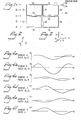
- Fig. 1 shows schematically a coil, which is utilized according to the invention,and indicates different transport directions A-E for an indicating device in the form of said strip
- Fig. 2 shows a co-ordinate system, in which the coil in Fig. 1 is located in the x-y plane
- Fig. 3 shows a strip oriented in the x-direction, y-direction and z-direction, respectively
- Figs. 4a-4f show schematically the signal intensity (v), which is obtained at the passage of a strip past the coil in Fig. 1, depending on the .
- FIG. 5 is an elucidating Figure to illustrate a coil set comprising three coils according to Fig. 1
- Fig. 6 shows a monitoring zone
- Fig. 7 shows schematically a complete device for indicating the presence of an indicating device in an investigation zone.
- a device for detecting the presence of an indicating device is shown schematically, which indicating device, for example, has the form of a strip of a highly permeable material and is located in a restricted investigation zone 1, which is defined by two parallel screens 2,3, which comprise coils for emitting and receiving magnetic alternating fields.
- a feeding device 4 is provided for emitting a field of a certain frequency by means of emitting coils.
- the indicating device 5 is provided to receive said fields and to re-emit an alternating field, which comprises a frequency other than that of the emitted frequency.
- a receiving equipment is provided for receiving a signal arising in the receiving coils due to the alternating field re-emitted by the indicating device.
- the receiving equipment 6 comprises a receiver 7 and a detector circuit 8 capable to detect and interpret the signal received.
- the detector circuit 8 receives a signal, which agrees with the criterion or criteria applying when an indicating device is present in the investigation zone, the detector circuit 8 emits a signal to an alarming device 9 of known kind.
- the system described above can be similar to that described in said Swedish patent.
- the present invention can be used at an indicating device of a different kind, for example an indicating device in the form of a resonance circuit.
- the receiving coils are designed in a special way.
- the receiving coils comprise at least two coil sets, as described below. In Fig. 5 three coil sets are shown, where a first one 10 is shown by fully drawn lines, a second one 10' is shown by dash-dotted lines, and a third one 10" by dashed lines.
- a coil set 10 is shown in greater detail.
- the coil set 10 is a so-called balanced coil wound to a configuration corresponding to two substantially rectangular eights, which are located to the side of each other in the same plane.
- the coil set 10 has such a configuration, that the outer winding portions 11-18 form a rectangle, and the remaining winding portions 19-22 divide the rectangle into four smaller rectangles of equal size.
- the coil set 10 is wound so that from one pole 23 of it the conductor extends to the second pole 24 via the winding portions as follows: 11,19,20, 1 2,11,19, 20,13,14,21, 20 , 13 , 1 4, 21 , 22 , 16 , 15 , 2 1 ,22, 1 6, 15 , 21,22, 17 , 1 8,19, 22, 17, 18,19,20, 12.
- the winding portions 11-18 thus, comprise two turns, and the winding portions 19-22 comprise four turns.
- the coil portions, thus, which are constituted by said smaller rectangles are wound so, that the rectangles in the first and third quadrant are wound in the same direction while the rectangles in the second and fourth quadrant are wound in opposite directions.
- Fig. 3 an indicating device is shown, which has the form of a strip of a highly permeable material in three different orientations x,y and z according to the co-ordinate system in Fig. 2.
- the coil set 10 is assumed to be located in the x-y plane.
- A-E indicate five different imagined transport paths for a strip 5 when it is transported in the x-y plane past the coil set 10.
- A thus, implies that the strip is transported along the winding portions 18 and 1.
- B implies, that the strip is transported along a path located centrally between the winding portions 18, 11 and, respectively, 22, 20.
- C-E have a corresponding meaning.
- the dimensions of the strip 5 are only, for example, 25 x 2 x 0.1 mm while the coil set can have outer dimensions of, for example, 100 x 80 cm.
- Figs. 4a-4f the signal intensity (v) is illustrated, which is obtained when a strip 5 is moved in the x-direction according to the paths A-E.
- the transport path (PATH) and the orientation (ORIENT) of the strip are indicated.
- the signal (v) is shown which is received when the strip is x-oriented and follows the path A in Fig. 1.
- the indication "-E” implies, that a signal corresponding to the one shown, but with opposite sign, is received when the strip is x-oriented and follows the path E.
- the Figs. 4b-4f show in a corresponding way the signal for different orientations of the strip when it follows different paths.
- the receiving device comprises at least two coil sets 10, 10'; of the kind shown in Fig. 1, where each coil set 10, 10', 10" is a balanced coil wound to a configuration corresponding to two substantially rectangular eights located to the side of each other in the same plane.
- the coil sets 10, 10', 10" are located in parallel with each other and preferably in the same plane.
- Each of the coil sets is offset, relative to an adjacent coil set, in a direction in parallel with said plane through a distance (a/-) corresponding to about one fourth of the distance (2a) in the offset direction between the outer opposed sides 18,11;14,15 in a coil set 10.
- the paths A-E of the second coil set 10' are offset relative to the paths A-E of the first coil set.
- the path B of the coil 10 corresponds to the path A of the coil 10';
- the path C of the coil 10 corresponds to the path B of the coil 10' , a.s.o.
- a signal (v) is received from one or the other or from both of the coil sets 10, 10', irrespective of which orientation the strip has and which path it follows.
- each coil set partially overlaps an adjacent coil set, so that two respective opposed winding portions 16,17; 12,13, and 25,26; 27,28, respectively, of each of the coil sets 10, 10" are locat- ed along two respective straight lines, i.e. as illustrated in Fig. 5.
- a set of r ec- eiving coils comprises at least four coil sets in a vertical plane where they are offset relative to each other in the way stated above in a vertical plane, and where the total height of the coil sets exceeds 1,5 meters, preferably 1,7 meters, and the total width of the coil sets exceeds 0,5 m and preferably is about 0.8 m.
- a vertical screen 2;3 of such design is shown in Fig. 6.
- the uppermost located coil set extends from the indicated level 36 to the level 32.
- the winding portions according to Fig. 1 are marked in Fig. 6.
- the second coil set extends between the levels 35 and 31, the third coil set between the levels 34 and 30, and the fourth coil set between the levels 33 and 29.
- two sets of receiving coils i.e. screens 2,3, are positioned in parallel with each other and at a distance from each other of about 0.5 to 1.0 m, as illustrated in Fig. 6, whereby a restricted investigation zone 1 is formed between the same.
- the receiving device preferably is capable to receive alternating fields of such frequency, that the wave length is long compared to the height and width of the coil sets, especially a frequency below 100 MHz, preferably below 30 MHz.
- the coil sets act as fully balanced coils to interferences arising from a place located at a distance from the coils, which distance corresponds to a minimum distance of about 4a to 6a, see Fig. 5.
- so-called remote interferences from electric devices in the premises, are effectively oppressed.
- the said coil sets are connected via conductors 37,38 to the receiver 7, where emf generated in the coils are sensed.
- the said emitting coils (not shown) preferably extend along the periphery 41-44; 45- 1 18 formed by the coil sets. These emitting coils are connected via conductors 39,40 to the feed equipment 4.
- the winding portions of the coil sets extend in tubular portions, only five of which are marked in Fig. 6 by the numeral 49.
- the ends of the tubular portions are attached to each other so, that a frame is formed, whibh has the configuration of a grid forming a number of rectangular squares, as illustrated in Fig. 6.
- This embodiment provides the advantage, that the staff easily can monitor persons passing tile investigation zone 1.
- the present invention can be varied in different ways without abandoning the invention idea, that at least two coil sets are used which are offset relative to each other.
Landscapes
- Engineering & Computer Science (AREA)
- Physics & Mathematics (AREA)
- General Physics & Mathematics (AREA)
- Automation & Control Theory (AREA)
- Computer Security & Cryptography (AREA)
- Electromagnetism (AREA)
- Artificial Intelligence (AREA)
- Computer Vision & Pattern Recognition (AREA)
- Theoretical Computer Science (AREA)
- Signal Processing (AREA)
- Geophysics And Detection Of Objects (AREA)
- Input Circuits Of Receivers And Coupling Of Receivers And Audio Equipment (AREA)
- Saccharide Compounds (AREA)
- Manufacture, Treatment Of Glass Fibers (AREA)
- Burglar Alarm Systems (AREA)
- Investigating Or Analyzing Materials By The Use Of Magnetic Means (AREA)
- Pharmaceuticals Containing Other Organic And Inorganic Compounds (AREA)
- Transition And Organic Metals Composition Catalysts For Addition Polymerization (AREA)
- Control And Other Processes For Unpacking Of Materials (AREA)
- Lubrication Of Internal Combustion Engines (AREA)
- Pinball Game Machines (AREA)
- Grinding Of Cylindrical And Plane Surfaces (AREA)
- Control Of Motors That Do Not Use Commutators (AREA)
Applications Claiming Priority (2)
| Application Number | Priority Date | Filing Date | Title |
|---|---|---|---|
| SE8600258 | 1986-01-21 | ||
| SE8600258A SE451166C (sv) | 1986-01-21 | 1986-01-21 | Mottagaranordning foer att detektera naervaro av en indikeringsanordning i en begraensad undersoekningszon |
Publications (3)
| Publication Number | Publication Date |
|---|---|
| EP0238458A2 true EP0238458A2 (de) | 1987-09-23 |
| EP0238458A3 EP0238458A3 (de) | 1989-10-04 |
| EP0238458B1 EP0238458B1 (de) | 1999-09-15 |
Family
ID=20363169
Family Applications (1)
| Application Number | Title | Priority Date | Filing Date |
|---|---|---|---|
| EP87850009A Expired - Lifetime EP0238458B1 (de) | 1986-01-21 | 1987-01-16 | Anwesenheitsdetektionsempfangsvorrichtung |
Country Status (12)
| Country | Link |
|---|---|
| US (1) | US4845509A (de) |
| EP (1) | EP0238458B1 (de) |
| JP (1) | JPH0782593B2 (de) |
| AT (1) | ATE184723T1 (de) |
| AU (1) | AU594745B2 (de) |
| CA (1) | CA1278352C (de) |
| DE (1) | DE3752291T2 (de) |
| DK (1) | DK167511B1 (de) |
| ES (1) | ES2136054T3 (de) |
| FI (1) | FI86233C (de) |
| SE (1) | SE451166C (de) |
| WO (1) | WO1987004551A1 (de) |
Families Citing this family (12)
| Publication number | Priority date | Publication date | Assignee | Title |
|---|---|---|---|---|
| US5103234A (en) * | 1987-08-28 | 1992-04-07 | Sensormatic Electronics Corporation | Electronic article surveillance system |
| ZA889254B (en) * | 1987-12-10 | 1990-08-29 | Uniscan Ltd | Powering and communication apparatus and method(s) |
| US5126749A (en) * | 1989-08-25 | 1992-06-30 | Kaltner George W | Individually fed multiloop antennas for electronic security systems |
| USD318247S (en) | 1989-09-11 | 1991-07-16 | Checkpoint Systems, Inc. | Electronic article surveillance antenna for a theft detection system |
| USD317272S (en) | 1989-10-06 | 1991-06-04 | Minnesota Mining And Manufacturing Company | Electronic article surveillance unit |
| US5142292A (en) * | 1991-08-05 | 1992-08-25 | Checkpoint Systems, Inc. | Coplanar multiple loop antenna for electronic article surveillance systems |
| US5404147A (en) * | 1992-10-28 | 1995-04-04 | Sensormatic Electronics Corporation | EAS system loop antenna having three loops of different area |
| DE4436974B4 (de) * | 1994-10-15 | 2004-04-01 | Meto International Gmbh | Markierungselement zur Sicherung von Artikeln gegen Diebstahl |
| DE4440314A1 (de) * | 1994-11-11 | 1996-05-15 | Esselte Meto Int Gmbh | Markierungselement zur Sicherung von Artikeln gegen Diebstahl |
| FR2745103B1 (fr) * | 1996-02-15 | 1998-04-03 | Bourgogne Grasset | Dispositif de rangement pour jetons de jeu |
| PT1766589E (pt) | 2005-04-07 | 2013-08-23 | Gaming Partners Int | Processo de gestão de uma pluralidade de leitores de fichas incorporando um microprocessador electrónico e equipamento de implementação do dito processo |
| USD867192S1 (en) | 2018-06-06 | 2019-11-19 | Donald R. Sweeney | Metal detector |
Family Cites Families (11)
| Publication number | Priority date | Publication date | Assignee | Title |
|---|---|---|---|---|
| US4016553A (en) * | 1975-06-27 | 1977-04-05 | Knogo Corporation | Article detection system with near field electromagnetic wave control |
| SE429382B (sv) * | 1977-05-09 | 1983-08-29 | Knogo Corp | Sett och apparat for detektering av obehorig passage av foremal genom en fragezon |
| US4118693A (en) * | 1977-05-09 | 1978-10-03 | Knogo Corporation | Method and apparatus for producing uniform electromagnetic fields in an article detection system |
| US4135184A (en) * | 1977-08-31 | 1979-01-16 | Knogo Corporation | Electronic theft detection system for monitoring wide passageways |
| US4243980A (en) * | 1978-02-17 | 1981-01-06 | Lichtblau G J | Antenna system for electronic security installations |
| DK145169C (da) * | 1978-08-09 | 1983-02-21 | Security Prod Int | Anlaeg til registrering af en passage af en genstand gennem etforudbestemt omraade |
| US4373163A (en) * | 1980-07-14 | 1983-02-08 | I.D. Engineering, Inc. | Loop antenna for security systems |
| US4309697A (en) * | 1980-10-02 | 1982-01-05 | Sensormatic Electronics Corporation | Magnetic surveillance system with odd-even harmonic and phase discrimination |
| GB2133660B (en) * | 1982-11-09 | 1986-07-30 | Tag Radionics Ltd | Transponder detection systems |
| DE3578228D1 (de) * | 1984-02-15 | 1990-07-19 | Esselte Meto Eas Int Ab | Verfahren und anordnung zur detektion eines anzeigegeraets. |
| US4633250A (en) * | 1985-01-07 | 1986-12-30 | Allied Corporation | Coplanar antenna for proximate surveillance systems |
-
1986
- 1986-01-21 SE SE8600258A patent/SE451166C/sv not_active IP Right Cessation
-
1987
- 1987-01-07 CA CA000526898A patent/CA1278352C/en not_active Expired - Lifetime
- 1987-01-16 US US07/105,300 patent/US4845509A/en not_active Expired - Fee Related
- 1987-01-16 AT AT87850009T patent/ATE184723T1/de not_active IP Right Cessation
- 1987-01-16 AU AU68994/87A patent/AU594745B2/en not_active Ceased
- 1987-01-16 EP EP87850009A patent/EP0238458B1/de not_active Expired - Lifetime
- 1987-01-16 DE DE3752291T patent/DE3752291T2/de not_active Expired - Fee Related
- 1987-01-16 JP JP62500756A patent/JPH0782593B2/ja not_active Expired - Lifetime
- 1987-01-16 WO PCT/SE1987/000015 patent/WO1987004551A1/en not_active Ceased
- 1987-01-16 ES ES87850009T patent/ES2136054T3/es not_active Expired - Lifetime
- 1987-09-18 DK DK489387A patent/DK167511B1/da not_active IP Right Cessation
- 1987-09-18 FI FI874087A patent/FI86233C/fi not_active IP Right Cessation
Also Published As
| Publication number | Publication date |
|---|---|
| EP0238458A3 (de) | 1989-10-04 |
| FI874087A7 (fi) | 1987-09-18 |
| SE451166C (sv) | 1990-12-10 |
| JPS63502226A (ja) | 1988-08-25 |
| SE8600258D0 (sv) | 1986-01-21 |
| WO1987004551A1 (en) | 1987-07-30 |
| FI86233C (fi) | 1992-07-27 |
| ATE184723T1 (de) | 1999-10-15 |
| DE3752291D1 (de) | 1999-10-21 |
| DK489387A (da) | 1987-09-18 |
| AU594745B2 (en) | 1990-03-15 |
| JPH0782593B2 (ja) | 1995-09-06 |
| FI874087A0 (fi) | 1987-09-18 |
| US4845509A (en) | 1989-07-04 |
| AU6899487A (en) | 1987-08-14 |
| FI86233B (fi) | 1992-04-15 |
| SE8600258L (sv) | 1987-07-22 |
| DE3752291T2 (de) | 2000-03-23 |
| DK167511B1 (da) | 1993-11-08 |
| DK489387D0 (da) | 1987-09-18 |
| CA1278352C (en) | 1990-12-27 |
| SE451166B (sv) | 1987-09-07 |
| EP0238458B1 (de) | 1999-09-15 |
| ES2136054T3 (es) | 1999-11-16 |
Similar Documents
| Publication | Publication Date | Title |
|---|---|---|
| EP0407532B1 (de) | Antennen-struktur für elektronisches bewachungssystem für gegenstände | |
| US4751516A (en) | Antenna system for magnetic and resonant circuit detection | |
| US4845509A (en) | Multiple loop receiving device in a security system | |
| US4135184A (en) | Electronic theft detection system for monitoring wide passageways | |
| EP0615217B1 (de) | Elektronisches Warenüberwachsungssystem mit Verbesserter geometrische Anordnung | |
| EP0536288B1 (de) | Metallsuchgerät | |
| US4866455A (en) | Antenna system for magnetic and resonant circuit detection | |
| US6362739B1 (en) | Passive security device for detecting ferromagnetic objects | |
| CA2251326C (en) | Electronic article surveillance system | |
| GB1585302A (en) | Article detection apparatus | |
| DK156857B (da) | Antennesystem til elektroniske sikkerhedsinstallationer | |
| CA1295030C (en) | Antipilferage systems | |
| KR940009084B1 (ko) | 자기 및 공명회로 검출용 안테나 시스템 | |
| DE602004005419T2 (de) | Elektronisches artikelsicherungsantennensystem mit grossem ausgang | |
| US5883574A (en) | Arrangement for preventing disturbances in electronic alarm systems | |
| US4254413A (en) | E Field balanced phase intrusion alarm | |
| EP0045335A1 (de) | Eindringungsmelder nach dem E-Feldprinzip mit balancierter Phase | |
| AU633247B2 (en) | Antenna system for magnetic and resonant circuit detection | |
| CA1141839A (en) | E field balanced phase intrusion alarm | |
| WO1993011516A1 (en) | Method of and system for surveillance and detection using magnetic markers |
Legal Events
| Date | Code | Title | Description |
|---|---|---|---|
| PUAI | Public reference made under article 153(3) epc to a published international application that has entered the european phase |
Free format text: ORIGINAL CODE: 0009012 |
|
| AK | Designated contracting states |
Kind code of ref document: A2 Designated state(s): AT BE CH DE ES FR GB IT LI LU NL SE |
|
| PUAL | Search report despatched |
Free format text: ORIGINAL CODE: 0009013 |
|
| AK | Designated contracting states |
Kind code of ref document: A3 Designated state(s): AT BE CH DE ES FR GB IT LI LU NL SE |
|
| 17P | Request for examination filed |
Effective date: 19891114 |
|
| 17Q | First examination report despatched |
Effective date: 19911106 |
|
| RAP1 | Party data changed (applicant data changed or rights of an application transferred) |
Owner name: ESSELTE METO INTERNATIONAL GMBH |
|
| RAP1 | Party data changed (applicant data changed or rights of an application transferred) |
Owner name: METO INTERNATIONAL GMBH |
|
| GRAG | Despatch of communication of intention to grant |
Free format text: ORIGINAL CODE: EPIDOS AGRA |
|
| GRAG | Despatch of communication of intention to grant |
Free format text: ORIGINAL CODE: EPIDOS AGRA |
|
| GRAH | Despatch of communication of intention to grant a patent |
Free format text: ORIGINAL CODE: EPIDOS IGRA |
|
| GRAH | Despatch of communication of intention to grant a patent |
Free format text: ORIGINAL CODE: EPIDOS IGRA |
|
| GRAA | (expected) grant |
Free format text: ORIGINAL CODE: 0009210 |
|
| AK | Designated contracting states |
Kind code of ref document: B1 Designated state(s): AT BE CH DE ES FR GB IT LI LU NL SE |
|
| REF | Corresponds to: |
Ref document number: 184723 Country of ref document: AT Date of ref document: 19991015 Kind code of ref document: T |
|
| REG | Reference to a national code |
Ref country code: CH Ref legal event code: EP |
|
| ITF | It: translation for a ep patent filed | ||
| REF | Corresponds to: |
Ref document number: 3752291 Country of ref document: DE Date of ref document: 19991021 |
|
| REG | Reference to a national code |
Ref country code: ES Ref legal event code: FG2A Ref document number: 2136054 Country of ref document: ES Kind code of ref document: T3 |
|
| REG | Reference to a national code |
Ref country code: CH Ref legal event code: NV Representative=s name: BUGNION S.A. |
|
| ET | Fr: translation filed | ||
| PG25 | Lapsed in a contracting state [announced via postgrant information from national office to epo] |
Ref country code: LU Free format text: LAPSE BECAUSE OF NON-PAYMENT OF DUE FEES Effective date: 20000116 |
|
| PLBE | No opposition filed within time limit |
Free format text: ORIGINAL CODE: 0009261 |
|
| STAA | Information on the status of an ep patent application or granted ep patent |
Free format text: STATUS: NO OPPOSITION FILED WITHIN TIME LIMIT |
|
| 26N | No opposition filed | ||
| REG | Reference to a national code |
Ref country code: GB Ref legal event code: IF02 |
|
| PGFP | Annual fee paid to national office [announced via postgrant information from national office to epo] |
Ref country code: AT Payment date: 20040211 Year of fee payment: 18 |
|
| PGFP | Annual fee paid to national office [announced via postgrant information from national office to epo] |
Ref country code: ES Payment date: 20040224 Year of fee payment: 18 |
|
| PG25 | Lapsed in a contracting state [announced via postgrant information from national office to epo] |
Ref country code: AT Free format text: LAPSE BECAUSE OF NON-PAYMENT OF DUE FEES Effective date: 20050116 |
|
| PG25 | Lapsed in a contracting state [announced via postgrant information from national office to epo] |
Ref country code: ES Free format text: LAPSE BECAUSE OF NON-PAYMENT OF DUE FEES Effective date: 20050117 |
|
| PGFP | Annual fee paid to national office [announced via postgrant information from national office to epo] |
Ref country code: GB Payment date: 20050413 Year of fee payment: 19 |
|
| PGFP | Annual fee paid to national office [announced via postgrant information from national office to epo] |
Ref country code: SE Payment date: 20050512 Year of fee payment: 19 |
|
| PGFP | Annual fee paid to national office [announced via postgrant information from national office to epo] |
Ref country code: DE Payment date: 20050701 Year of fee payment: 19 |
|
| PGFP | Annual fee paid to national office [announced via postgrant information from national office to epo] |
Ref country code: CH Payment date: 20050707 Year of fee payment: 19 |
|
| PGFP | Annual fee paid to national office [announced via postgrant information from national office to epo] |
Ref country code: FR Payment date: 20050708 Year of fee payment: 19 |
|
| PGFP | Annual fee paid to national office [announced via postgrant information from national office to epo] |
Ref country code: NL Payment date: 20050728 Year of fee payment: 19 |
|
| PGFP | Annual fee paid to national office [announced via postgrant information from national office to epo] |
Ref country code: BE Payment date: 20050802 Year of fee payment: 19 |
|
| PG25 | Lapsed in a contracting state [announced via postgrant information from national office to epo] |
Ref country code: GB Free format text: LAPSE BECAUSE OF NON-PAYMENT OF DUE FEES Effective date: 20060116 |
|
| PG25 | Lapsed in a contracting state [announced via postgrant information from national office to epo] |
Ref country code: SE Free format text: LAPSE BECAUSE OF NON-PAYMENT OF DUE FEES Effective date: 20060117 |
|
| PG25 | Lapsed in a contracting state [announced via postgrant information from national office to epo] |
Ref country code: LI Free format text: LAPSE BECAUSE OF NON-PAYMENT OF DUE FEES Effective date: 20060131 Ref country code: FR Free format text: LAPSE BECAUSE OF NON-PAYMENT OF DUE FEES Effective date: 20060131 Ref country code: CH Free format text: LAPSE BECAUSE OF NON-PAYMENT OF DUE FEES Effective date: 20060131 Ref country code: BE Free format text: LAPSE BECAUSE OF NON-PAYMENT OF DUE FEES Effective date: 20060131 |
|
| PGFP | Annual fee paid to national office [announced via postgrant information from national office to epo] |
Ref country code: IT Payment date: 20060131 Year of fee payment: 20 |
|
| REG | Reference to a national code |
Ref country code: ES Ref legal event code: FD2A Effective date: 20050117 |
|
| PG25 | Lapsed in a contracting state [announced via postgrant information from national office to epo] |
Ref country code: NL Free format text: LAPSE BECAUSE OF NON-PAYMENT OF DUE FEES Effective date: 20060801 Ref country code: DE Free format text: LAPSE BECAUSE OF NON-PAYMENT OF DUE FEES Effective date: 20060801 |
|
| REG | Reference to a national code |
Ref country code: CH Ref legal event code: PL |
|
| EUG | Se: european patent has lapsed | ||
| GBPC | Gb: european patent ceased through non-payment of renewal fee |
Effective date: 20060116 |
|
| NLV4 | Nl: lapsed or anulled due to non-payment of the annual fee |
Effective date: 20060801 |
|
| REG | Reference to a national code |
Ref country code: FR Ref legal event code: ST Effective date: 20060929 |
|
| BERE | Be: lapsed |
Owner name: *METO INTERNATIONAL G.M.B.H. Effective date: 20060131 |