EP0238752B1 - Behälter für Datenspeicherelemente in Kombination mit einem Aufzeichnungs-/Wiedergabegerät zur Aufnahme des Behälters - Google Patents
Behälter für Datenspeicherelemente in Kombination mit einem Aufzeichnungs-/Wiedergabegerät zur Aufnahme des Behälters Download PDFInfo
- Publication number
- EP0238752B1 EP0238752B1 EP19860309148 EP86309148A EP0238752B1 EP 0238752 B1 EP0238752 B1 EP 0238752B1 EP 19860309148 EP19860309148 EP 19860309148 EP 86309148 A EP86309148 A EP 86309148A EP 0238752 B1 EP0238752 B1 EP 0238752B1
- Authority
- EP
- European Patent Office
- Prior art keywords
- magazine
- door
- casing
- storage units
- data storage
- Prior art date
- Legal status (The legal status is an assumption and is not a legal conclusion. Google has not performed a legal analysis and makes no representation as to the accuracy of the status listed.)
- Expired
Links
- 238000013500 data storage Methods 0.000 title claims description 12
- 230000037431 insertion Effects 0.000 claims description 10
- 238000003780 insertion Methods 0.000 claims description 10
- 230000014759 maintenance of location Effects 0.000 claims description 3
- 210000000707 wrist Anatomy 0.000 description 2
- 230000003287 optical effect Effects 0.000 description 1
Images


Classifications
-
- G—PHYSICS
- G11—INFORMATION STORAGE
- G11B—INFORMATION STORAGE BASED ON RELATIVE MOVEMENT BETWEEN RECORD CARRIER AND TRANSDUCER
- G11B15/00—Driving, starting or stopping record carriers of filamentary or web form; Driving both such record carriers and heads; Guiding such record carriers or containers therefor; Control thereof; Control of operating function
- G11B15/675—Guiding containers, e.g. loading, ejecting cassettes
- G11B15/68—Automatic cassette changing arrangements; automatic tape changing arrangements
- G11B15/682—Automatic cassette changing arrangements; automatic tape changing arrangements with fixed magazines having fixed cassette storage cells, e.g. in racks
- G11B15/6825—Details of magazines, e.g. removable, adapted for cassettes of different sizes
Definitions
- the present invention relates to the combination of a magazine for holding data-storage units, and apparatus arranged to receive the magazine and to write data to and/or read data from the data storage units of the magazine.
- GB-A 1 302 389 discloses a magazine for holding a vertical stack of horizontally disposed tape cartridges.
- the magazine is horizontally insertable into a front opening in tape record/playback apparatus.
- a handle is provided on the wall of the magazine that faces outwards following the insertion operation.
- a disadvantage of the arrangement described in GB-A 1 302 289 is that during insertion of the magazine into the record/playback apparatus, the weight of the magazine provides a considerable eccentric load on the hand and wrist of the user. This results in lack of control and general difficulty in the positioning and insertion of the magazine into the apparatus.
- a magazine arranged to hold a plurality of de- ta storage units
- the magazine comprising a housing provided on top with a carrying handle in combination with an apparatus arranged to receive the magazine with data storage units held therein and to write data to and/or read data from the data storage units
- the apparatus includes a casing with an upright door arranged to tilt open outwardly by pivotal movement about a substantially horizontal axis lying in the region of the bottom of the door, the door when open permitting the magazine to be inserted down past the back of the door into the apparatus after the magazine has first been tilted from its normal carrying orientation.
- US-A 3 877 075 discloses a cassette recorder having an upright door which can be tilted open outwardly by pivotal movement about a substantially horizontal axis near the bottom of the door. The door, when open, permits a cassette to be inserted down past the back of the door into the recorder.
- this known loading principle relates to loading a single cassette into a recorder, whereby the weight of the cassette is of no importance.
- the casing door is rearwardly provided with guide elements arranged to engage in guide channels externally formed on opposite sides of the magazine housing.
- correct seating of the magazine within the apparatus is achieved by the provision of locating stops on a base member of the apparatus, the magazine being arranged to seat on these stops after its insertion into the apparatus casing and closure of the casing door.
- resilient means may be provided on the casing door or body to apply a downwards force to the magazine whereby to hold the latter ahainst said locating stops.
- fixed stop means are also provided for locating the magazine in an inwards direction of the apparatus; again resilient means can be positioned to urge the magazine against these stop means upon closure of the casing door. In this manner, the magazine may be located relative to a fixed part of the apparatus both vertically and horizontally.
- the casing door and the magazine housing are provided with respective window openings which after the magazine has been inserted into the apparatus, line up to enable a user to see the data storage units, if any, present in the magazine.
- the magazine is provided with retention means for individually holding each cartridge stored therein in position.
- the tape-cartridge magazine 10 shown in Figure I is arranged to hold six tape cartridges which, for example, are of a form similar to that described in US-A 3 692 255.
- the magazine 10 comprises an open-fronted housing provided on top with a carrying handle 12.
- the housing is made up of opposed side walls 13,14 interconnected by a base 15 and top 16, and a rear wall 17 formed with a vertical window 18 extending the full height of the housing.
- the side walls 13,14 are internally provided with five pairs of horizontal ledges 21 which serve to seat respective tape cartridges II, the housing base 15 seating a sixth cartridge II.
- the cartridges can be readily inserted and withdrawn from the housing by being slid in and out through the open front of the housing.
- Spring elements 22 fixed to the housing side walls 13,14 are arranged to engage corresponding recesses 23 in the sides of the cartridges II when the latter are fully inserted into the housing whereby to exert a small retention force lightly holding the cartridges in their fully-inserted positions.
- the two side walls 13,14 are externally formed with vertical guide channels 24 which are flared at their lower ends 25.
- the purpose of these channels 24 will be explained hereinafter.
- the magazine 10 When being used to carry one or more cartridges II, the magazine 10 is held by its handle 12 and depends vertically therefrom with the cartridges II substantially horizontal. In such a carrying position, the weight of the magazine and cartridges can be comfortably borne by the user.
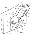
- Figure 2 illustrates the loading of the magazine 10 into the tape read/write apparatus 30 through an outwardly-opening door 31 provided in the front wall of a casing 32 of the apparatus.
- the apparatus itself may, for example, be of the form described and illustrated in our copending International Patent Application WO-A 86/02192 in which a selector mechanism operates to withdraw a selected cartridge from the magazine and transport it to a read/write station of the apparatus.
- the selector mechanism and the read/write station form no part of the present invention and will therefore not be further described herein.
- the structure of the door 31 is shown in Figures 3 and 4.
- the door 31 comprises a front panel 34 pivoted at its lower end about a horizontal shaft 33 mounted in the front wall of the casing 32.
- the door further comprises two side panels 35 extending rearwardly from the panel 34, and two comer base plates 36.
- the front panel 34 of the door 31 is formed with a window (see Figure 2).
- the door 31 When closed, the door 31 resides in an upright position flush with the rest of the front wall of the casing 32.
- a latch mechanism not shown, is provided to latch the door 31 in its closed position.
- the door is moved to an open position by release of the latch mechanism followed by pivotal movement about the shaft 33, the limit of this movement (and thus the fully-open position of the door) being defined by a two- arm linkage 37 extending between the door 31 and a point 38 fixed relative to the apparatus casing 32.
- the open position of the door is shown in dashed lines in Figures 3 and 4.
- the side panels 34 have their free, upright, edge portions 38 turned inwards to form guide elements for engaging corresponding ones of the guide channels 24 of the magazine 10.
- a base member 40 of the apparatus casing mounts four locating stops 41 and two locating stops 51. All six locating stops are machined with horizontal surfaces 52 which serve to seat the magazine after it has been loaded into the read/write apparatus and the door 31 closed.
- the corner base plates 36 are formed with corresponding apertures 41.
- a pair of spring elements 46 attached to the side panels 35 are arranged to engage the top side edges of the magazine 10 to apply a downwards force thereto whereby to hold the magazine down on the horizontal surfaces 52 of the locating stops 41,51; in this manner, the magazine is accurately located in the vertical direction after insertion into the apparatus.
- Each of the locating stops 51 is also machined with a vertical surface 53 and a sloping lead-in surface 54 (see Figure 3).
- a second pair of spring elements 47 fixed to the front panel 34 of the door serve to urge the magazine away from the panel so that as the door is closed, the inward bottom edge of the magazine is pushed against the lead-in surfaces of the stops 51 and moves down these surfaces to locate against the surfaces 53. In this manner, the magazine is accurately located in a horizontal, inwards, direction.
- the stops 41 may also be provided with lead-in surfaces to facilitate the sideways location of the magazine.
- the door 31 In use, to load the magazine into the read/write apparatus 30, the door 31 is moved into its open position illustrated in Figure 3. The magazine is then tilted from its normal carrying position to line up with the open door 31 (see Figure 2). Next, the magazine is lowered so as to engage the guide elements 39 of the door in the guide channels 24 formed in the side walls of the magazine, this engagement being facilitated by the flared lower ends 25 of the guide channels.
- the magazine Upon engagement of the guide elements 39 in the channels 24, the magazine can be rapidly lowered down the back of the door to come to rest on the corner base plates 36 of the door. Thereafter, the door is closed bringing the magazine into an upright position in which it is seated on the locating stops 41 rather than the base plates 36.
- the spring elements 46 engage the top side edges of the magazine to hold it down on the horizontal surfaces 52 of the stops 41,51 while the spring elements 47 locate the magazine against the vertical surfaces 53 of the stops 51.
- the rake of the handle 12 of the magazine 10 reduces the height of the door opening required to ensure unobstructed passage of the magazine into the apparatus upon closure of the door 31.
- the window 45 provided in the front panel 34 of the door 31 is so positioned as to line up with the window 18 in the magazine 10; as a result a user can see into the magazine from outside of the apparatus in order to ascertain how many cartridges II are present.
- the described magazine can be provided with additional features as desired.
- a selectively- settable write-protect arrangement can be installed on the magazine to cooperate with complimentary means provided in the apparatus in order to pre- . vent (either physically or otherwise) the writing of data to any of the cartridges stored in the magazine.
- the magazine 10 is arranged to hold tape cartridges in a horizontal attitude
- other types of data storage units could equally well be held in the magazine in any appropriate orientation.
- the magazine could be designed to hold optical storage discs positioned vertically.
Landscapes
- Automatic Tape Cassette Changers (AREA)
- Packaging Of Annular Or Rod-Shaped Articles, Wearing Apparel, Cassettes, Or The Like (AREA)
Claims (7)
Applications Claiming Priority (2)
| Application Number | Priority Date | Filing Date | Title |
|---|---|---|---|
| GB8601827 | 1986-01-25 | ||
| GB868601827A GB8601827D0 (en) | 1986-01-25 | 1986-01-25 | Magazine for data-storage units |
Publications (2)
| Publication Number | Publication Date |
|---|---|
| EP0238752A1 EP0238752A1 (de) | 1987-09-30 |
| EP0238752B1 true EP0238752B1 (de) | 1990-02-07 |
Family
ID=10591941
Family Applications (1)
| Application Number | Title | Priority Date | Filing Date |
|---|---|---|---|
| EP19860309148 Expired EP0238752B1 (de) | 1986-01-25 | 1986-11-24 | Behälter für Datenspeicherelemente in Kombination mit einem Aufzeichnungs-/Wiedergabegerät zur Aufnahme des Behälters |
Country Status (3)
| Country | Link |
|---|---|
| EP (1) | EP0238752B1 (de) |
| DE (1) | DE3669005D1 (de) |
| GB (1) | GB8601827D0 (de) |
Families Citing this family (7)
| Publication number | Priority date | Publication date | Assignee | Title |
|---|---|---|---|---|
| US4983387A (en) | 1986-05-19 | 1991-01-08 | Viral Technologies Inc. | HIV related peptides, immunogenic antigens, and use therefor as subunit vaccine for AIDS virus |
| US5004393A (en) * | 1989-09-29 | 1991-04-02 | Storage Technology Corporation | Autoloader magazine for tape cartridges and method therefor |
| US5495374A (en) * | 1994-04-19 | 1996-02-27 | International Business Machines Corporation | Automatic loader mechanism for magnetic tape cartridge with tension control |
| US5576911A (en) * | 1994-10-25 | 1996-11-19 | Sony Corporation | Cartridge locking mechanism and interface |
| US5659440A (en) * | 1995-03-14 | 1997-08-19 | International Business Machines Corporation | Data cartridge magazine with interface to automatic cartridge accessing devices |
| US6126257A (en) * | 1999-03-03 | 2000-10-03 | Storage Technology Corporation | Two position removable quick load tape cartridge magazine |
| US6411462B1 (en) | 1999-10-26 | 2002-06-25 | Storage Technology Corporation | Small library cartridge access mail slot method |
Family Cites Families (8)
| Publication number | Priority date | Publication date | Assignee | Title |
|---|---|---|---|---|
| US3453397A (en) * | 1963-09-19 | 1969-07-01 | Cart Trac Inc | Shiftable magazine sound tape cartridge apparatus |
| US3326483A (en) * | 1965-06-17 | 1967-06-20 | Sarkes Tarzian | Magnetic tape cartridge for automatic tape cartridge changing mechanism |
| US3603597A (en) * | 1969-04-25 | 1971-09-07 | Bell & Howell Co | Tape recorder |
| JPS5146965Y2 (de) * | 1972-06-17 | 1976-11-12 | ||
| CH563643A5 (en) * | 1973-11-01 | 1975-06-30 | Dimatteo Joe M | Play back attachment for recorded sound tapes - has playback unit and magazine with tape cassettes |
| US4164765A (en) * | 1977-12-07 | 1979-08-14 | National Computer Systems, Inc. | Carousel tape system |
| GB8425407D0 (en) * | 1984-10-08 | 1984-11-14 | Hewlett Packard Ltd | Magnetic tape storage |
| JPS61148660A (ja) * | 1984-12-21 | 1986-07-07 | Fujitsu Ltd | テ−プ引き出し機構 |
-
1986
- 1986-01-25 GB GB868601827A patent/GB8601827D0/en active Pending
- 1986-11-24 DE DE8686309148T patent/DE3669005D1/de not_active Expired - Fee Related
- 1986-11-24 EP EP19860309148 patent/EP0238752B1/de not_active Expired
Also Published As
| Publication number | Publication date |
|---|---|
| EP0238752A1 (de) | 1987-09-30 |
| GB8601827D0 (en) | 1986-02-26 |
| DE3669005D1 (de) | 1990-03-15 |
Similar Documents
| Publication | Publication Date | Title |
|---|---|---|
| US4800554A (en) | Disk magazine | |
| US4694957A (en) | Container for flat recording media | |
| US4401216A (en) | Media storage device | |
| EP0120124B1 (de) | Auflege- und Auswurfvorrichtung für Magnetplatten | |
| US4817079A (en) | Carrier retainer for disk cartridge | |
| US5761161A (en) | Automated library system with vertically translating input/output station | |
| US5644445A (en) | Cartridge library apparatus | |
| EP0709849A2 (de) | Plattenkassetten-Magazin | |
| US5719833A (en) | Apparatus for securing a cartridge engaging assembly within a cartridge handling system | |
| JPH08321154A (ja) | ハブ無しディスク用カートリッジ、ディスク・ドライブ及びディスク媒体ライブラリ | |
| US4794478A (en) | Improved loading device for cassette recording playback apparatus | |
| US4481617A (en) | Memory disc drive | |
| US5232275A (en) | Disc rack with holders which rest in a different position when unloaded than when loaded | |
| EP0205074A2 (de) | System zum Laden einer Plattenkassette in ein Plattenwiedergabegerät | |
| EP0490671B1 (de) | Speichergerät für Plattenkassetten | |
| EP0444623B1 (de) | Bandkassette-Lademechanismus | |
| CA1310749C (en) | Cassette tape recording and/or reproducing apparatus | |
| EP0238752A1 (de) | Behälter für Datenspeicherelemente in Kombination mit einem Aufzeichnungs-/Wiedergabegerät zur Aufnahme des Behälters | |
| US6760914B2 (en) | Disk reproducing apparatus | |
| EP0204072B1 (de) | Vorrichtung zur Speicherung und Ausgabe von Magnetbandkassetten | |
| US5179484A (en) | Mechanism for attaching and detaching disk cartridge from a disk drive | |
| KR100690554B1 (ko) | 이중 형식 용도를 위한 데이터 카트리지 케이스 | |
| US5610788A (en) | Media containing cartridge and drive therefor employing multiple registration points | |
| EP0566351B1 (de) | Automatischer Kassettenwechsler | |
| EP1031149B1 (de) | Roboter dockvorrichtung für kassettenbibliotheksystem mit kassettenspeicheranord-nung |
Legal Events
| Date | Code | Title | Description |
|---|---|---|---|
| PUAI | Public reference made under article 153(3) epc to a published international application that has entered the european phase |
Free format text: ORIGINAL CODE: 0009012 |
|
| 17P | Request for examination filed |
Effective date: 19870717 |
|
| AK | Designated contracting states |
Kind code of ref document: A1 Designated state(s): DE FR GB IT |
|
| 17Q | First examination report despatched |
Effective date: 19890717 |
|
| GRAA | (expected) grant |
Free format text: ORIGINAL CODE: 0009210 |
|
| AK | Designated contracting states |
Kind code of ref document: B1 Designated state(s): DE FR GB IT |
|
| PG25 | Lapsed in a contracting state [announced via postgrant information from national office to epo] |
Ref country code: IT Free format text: LAPSE BECAUSE OF FAILURE TO SUBMIT A TRANSLATION OF THE DESCRIPTION OR TO PAY THE FEE WITHIN THE PRE;WARNING: LAPSES OF ITALIAN PATENTS WITH EFFECTIVE DATE BEFORE 2007 MAY HAVE OCCURRED AT ANY TIME BEFORE 2007. THE CORRECT EFFECTIVE DATE MAY BE DIFFERENT FROM THE ONE RECORDED.SCRIBED TIME-LIMIT Effective date: 19900207 |
|
| REF | Corresponds to: |
Ref document number: 3669005 Country of ref document: DE Date of ref document: 19900315 |
|
| ET | Fr: translation filed | ||
| PLBE | No opposition filed within time limit |
Free format text: ORIGINAL CODE: 0009261 |
|
| STAA | Information on the status of an ep patent application or granted ep patent |
Free format text: STATUS: NO OPPOSITION FILED WITHIN TIME LIMIT |
|
| 26N | No opposition filed | ||
| PGFP | Annual fee paid to national office [announced via postgrant information from national office to epo] |
Ref country code: GB Payment date: 19910925 Year of fee payment: 6 |
|
| PGFP | Annual fee paid to national office [announced via postgrant information from national office to epo] |
Ref country code: FR Payment date: 19910927 Year of fee payment: 6 |
|
| PGFP | Annual fee paid to national office [announced via postgrant information from national office to epo] |
Ref country code: DE Payment date: 19910930 Year of fee payment: 6 |
|
| PG25 | Lapsed in a contracting state [announced via postgrant information from national office to epo] |
Ref country code: GB Effective date: 19921124 |
|
| REG | Reference to a national code |
Ref country code: FR Ref legal event code: CA |
|
| GBPC | Gb: european patent ceased through non-payment of renewal fee |
Effective date: 19921124 |
|
| PG25 | Lapsed in a contracting state [announced via postgrant information from national office to epo] |
Ref country code: FR Effective date: 19930730 |
|
| PG25 | Lapsed in a contracting state [announced via postgrant information from national office to epo] |
Ref country code: DE Effective date: 19930803 |
|
| REG | Reference to a national code |
Ref country code: FR Ref legal event code: ST |