EP0239014A2 - Méthode et dispositifs de régulation du point de fonctionnement d'étages finaux vidéo - Google Patents
Méthode et dispositifs de régulation du point de fonctionnement d'étages finaux vidéo Download PDFInfo
- Publication number
- EP0239014A2 EP0239014A2 EP87104064A EP87104064A EP0239014A2 EP 0239014 A2 EP0239014 A2 EP 0239014A2 EP 87104064 A EP87104064 A EP 87104064A EP 87104064 A EP87104064 A EP 87104064A EP 0239014 A2 EP0239014 A2 EP 0239014A2
- Authority
- EP
- European Patent Office
- Prior art keywords
- screen
- deflection
- vertical
- circuit
- circuit arrangement
- Prior art date
- Legal status (The legal status is an assumption and is not a legal conclusion. Google has not performed a legal analysis and makes no representation as to the accuracy of the status listed.)
- Withdrawn
Links
Images

Classifications
-
- H—ELECTRICITY
- H04—ELECTRIC COMMUNICATION TECHNIQUE
- H04N—PICTORIAL COMMUNICATION, e.g. TELEVISION
- H04N9/00—Details of colour television systems
- H04N9/64—Circuits for processing colour signals
- H04N9/645—Beam current control means
-
- G—PHYSICS
- G09—EDUCATION; CRYPTOGRAPHY; DISPLAY; ADVERTISING; SEALS
- G09G—ARRANGEMENTS OR CIRCUITS FOR CONTROL OF INDICATING DEVICES USING STATIC MEANS TO PRESENT VARIABLE INFORMATION
- G09G1/00—Control arrangements or circuits, of interest only in connection with cathode-ray tube indicators; General aspects or details, e.g. selection emphasis on particular characters, dashed line or dotted line generation; Preprocessing of data
- G09G1/04—Deflection circuits ; Constructional details not otherwise provided for
-
- G—PHYSICS
- G09—EDUCATION; CRYPTOGRAPHY; DISPLAY; ADVERTISING; SEALS
- G09F—DISPLAYING; ADVERTISING; SIGNS; LABELS OR NAME-PLATES; SEALS
- G09F13/00—Illuminated signs; Luminous advertising
- G09F13/20—Illuminated signs; Luminous advertising with luminescent surfaces or parts
- G09F13/22—Illuminated signs; Luminous advertising with luminescent surfaces or parts electroluminescent
- G09F2013/222—Illuminated signs; Luminous advertising with luminescent surfaces or parts electroluminescent with LEDs
-
- G—PHYSICS
- G09—EDUCATION; CRYPTOGRAPHY; DISPLAY; ADVERTISING; SEALS
- G09F—DISPLAYING; ADVERTISING; SIGNS; LABELS OR NAME-PLATES; SEALS
- G09F13/00—Illuminated signs; Luminous advertising
- G09F13/20—Illuminated signs; Luminous advertising with luminescent surfaces or parts
- G09F13/22—Illuminated signs; Luminous advertising with luminescent surfaces or parts electroluminescent
- G09F2013/227—Electroluminescent displays for vehicles
Definitions
- the invention relates to a circuit arrangement according to the type of the main claim.
- circuit arrangements for regulating the operating point of the video output stage are known, in which a voltage corresponding to the beam current is compared with a reference voltage during a line within the vertical frequency blanking interval after the vertical return and the result of the comparison is stored during the subsequent field.
- the operating point of the video output stage is set as a function of the stored voltage.
- the grid is usually written larger than the screen or the area of the screen released by a frame. It is therefore possible to start the vertical traverse to sense the beam current to a size suitable for deriving a measured value without this being visible on the screen.
- Color monitors intended as data display devices have therefore not previously been equipped with the control of the working point of the video output stages known from television receivers.
- the method according to the invention with the characterizing features of the main claim has the advantage that an operating point control is possible without the measurement lines being disruptive.
- a further development of the invention provides that the selected lines are written on a part of the screen covered by a frame.
- This development can be used advantageously in the usual color monitors, which are provided with a frame in front of the screen.
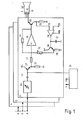
- the color value signals R, G, B are sent to the video amplifiers 4, 5, 6 supplied, the outputs of which are each connected to a cathode 7, 8, 9 of a color picture tube 10.
- the amplifiers 4, 5, 6 are constructed in the same way, only the amplifier 6 is shown in more detail.
- the color value signal arrives at a video preamplifier which, among other things, enables a contrast adjustment with the aid of an adjustable gain.
- the output of the video preamplifier 11 is connected via a capacitor 12 to the base of a transistor 13 connected as an emitter follower.
- the base of the transistor 13 is periodically connected to a constant potential during the line frequency return, as a result of which the video signals receive a constant DC voltage value in a manner known per se.
- the clamping circuit 14 is connected in the same way to the video amplifiers 4 and 5.
- the emitter of transistor 13 is connected to ground potential via load resistor 15, while the collector of transistor 13 is connected to a positive pole 16 of an operating voltage source.
- the color value signal is fed via a coupling resistor 17 to the input of an inverting amplifier 18, the no-load gain of which is so high that the effective amplification corresponds approximately to the ratio between the negative feedback resistor 19 and the coupling resistor 17.
- the video signals already have an amplitude sufficient to control the picture tube. They are conducted to the cathode 9 of the color picture tube 10 via an output transistor 20 connected as an emitter follower.
- a voltage can be removed which is proportional to the beam current. This is evaluated in a manner known per se in a control circuit for controlling the operating point of the video amplifier 18, 20.
- the voltage taken from the resistor 21 is fed to an input 23 of a differential amplifier 24, at the other input 25 of which there is a reference voltage.
- the differential amplifier 24 is a switchable operational amplifier, the output 26 of which only emits a signal when a corresponding signal is present at a switching input EN. During the remaining time, the output 26 is switched to high resistance. A pulse corresponding to an active line within the vertical frequency blanking interval after the beam return is now fed to the switching input EN. During this time, the result of the difference formation between the voltage corresponding to the beam current and a reference voltage is output by the differential amplifier 24 and a capacitor 27 is charged to this value. The switchable differential amplifier 24 and the capacitor 27 thus form a sample and hold circuit.
- the voltage present at the capacitor 27 is fed to the base of a transistor 28, which is connected together with the resistor 29 as an impedance converter.
- the base of transistor 28 forms a high-resistance input, so that the charge of capacitor 27 is practical during a field period table remains constant.
- the control circuit is provided in triplicate, in each case for one of the color value signals R, G, B.
- the control voltage reaches the input of the inverting amplifier 18 via an adjustable resistor 31.
- the gain of the by the video processor can be increased and the control circuit formed by the video amplifier can be set without changing the amplification for the video signal supplied by the transistor 13.
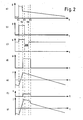
- Diagram a) represents the output voltage of a vertical deflection circuit.
- the vertical return occurs between t1 and t2. Due to the inductive component of the deflection coil and the faster current change during the return, a voltage pulse is generated between t1 and t2 in a manner known per se.
- the output voltage of the vertical deflection circuit is essentially time-linear.
- the color picture tube 10 (FIG. 1) is supplied with a vertical frequency blanking pulse, as shown in diagram b), which lasts until time t3.
- the cathode ray is released for one or more lines following the beam blanking with the aid of the pulse shown in diagram c). If it is released for several lines, the cathode ray between these lines is blanked out horizontally.
- the grid is usually written so large in television sets that it goes beyond the frame which covers the edge of the picture tube.
- the upper edge of the grid is therefore not visible in television sets, so that the lines that are blanked for the beam current control do not appear to be a nuisance either.
- the grid is written smaller so that it is completely visible.
- the electron beam is additionally deflected during these lines according to the present invention.
- a pulse according to diagram d) is generated in a pulse shaping circuit known per se and therefore not shown in detail.
- the pulse begins at t2, ie before the start of the measuring lines at t3. Furthermore, the safety edge of the pulse at t5 is slightly later than the end of the measuring lines at t4 for safety reasons.
- Diagram e) shows the course of the vertical deflection current in the usual raster representation. From the voltage pulse shown in diagram d), the current pulse shown in diagram f) is obtained, which is superimposed on the usual vertical deflection current, so that the one in diagram g) shown vertical deflection current arises.
- the beam jumps up by a predetermined value, so that the lines which are scanned for beam current control are written at a point on the screen which is covered by a frame .
- the beam can be deflected into an area that does not belong to the active screen, which is therefore not provided with phosphors.
- a series circuit comprising a vertical deflection coil 42, a capacitor 43 and a negative feedback resistor 44 is connected to the output of a vertical deflection circuit 41.
- a voltage can be removed from the negative feedback resistor 44, which voltage can be fed to a control input of the vertical deflection circuit 41. Since the voltage at the negative feedback resistor 44 corresponds to the current flowing through the vertical deflection coil 42, the vertical deflection current can be regulated in a manner known per se be that there is as linear a vertical deflection on the screen as possible.
- a vertical-frequency pulse is taken from the vertical deflection circuit 41 and fed to a pulse shaper 45, at the output of which the drive pulse shown in FIG. 2d) is present.
- This pulse is fed to an amplifier 46, the output of which is connected via a resistor 47 to the negative feedback path of the vertical deflection circuit.
- the amplifier 47 connects the resistor 47 in parallel with the negative feedback resistor 44.
- the resulting resistance value is thus smaller, as a result of which the voltage supplied to the vertical deflection circuit also becomes smaller with the same deflection current.
- a smaller deflection current is simulated, so to speak, to the vertical deflection circuit, as a result of which the deflection current is correspondingly increased during the actuation pulse.
- FIG. 4 shows another circuit for carrying out the method according to the invention, in which the vertical deflection circuit 41, the vertical deflection coil 42, the capacitor 43 and the negative feedback resistor 44 are arranged in the same way as in the circuit arrangement according to FIG. 3.
- a pulse shaper 45 is also used to shape the control pulse for an amplifier 48, which, however, does not engage in the negative feedback circuit as in the circuit arrangement according to FIG. 3, but rather supplies additional current directly to the deflection coil 42 via a resistor 49.
Landscapes
- Engineering & Computer Science (AREA)
- Multimedia (AREA)
- Signal Processing (AREA)
- Radar, Positioning & Navigation (AREA)
- Remote Sensing (AREA)
- Physics & Mathematics (AREA)
- Computer Hardware Design (AREA)
- General Physics & Mathematics (AREA)
- Theoretical Computer Science (AREA)
- Details Of Television Scanning (AREA)
- Transforming Electric Information Into Light Information (AREA)
- Picture Signal Circuits (AREA)
Applications Claiming Priority (2)
| Application Number | Priority Date | Filing Date | Title |
|---|---|---|---|
| DE19863610190 DE3610190A1 (de) | 1986-03-26 | 1986-03-26 | Verfahren und schaltungsanordnungen zur regelung des arbeitspunktes von videoendstufen |
| DE3610190 | 1986-03-26 |
Publications (2)
| Publication Number | Publication Date |
|---|---|
| EP0239014A2 true EP0239014A2 (fr) | 1987-09-30 |
| EP0239014A3 EP0239014A3 (fr) | 1990-02-21 |
Family
ID=6297317
Family Applications (1)
| Application Number | Title | Priority Date | Filing Date |
|---|---|---|---|
| EP87104064A Withdrawn EP0239014A3 (fr) | 1986-03-26 | 1987-03-19 | Méthode et dispositifs de régulation du point de fonctionnement d'étages finaux vidéo |
Country Status (5)
| Country | Link |
|---|---|
| US (1) | US4763048A (fr) |
| EP (1) | EP0239014A3 (fr) |
| DE (1) | DE3610190A1 (fr) |
| FI (1) | FI871305A7 (fr) |
| ZA (1) | ZA872202B (fr) |
Cited By (3)
| Publication number | Priority date | Publication date | Assignee | Title |
|---|---|---|---|---|
| EP0358987A3 (en) * | 1988-09-03 | 1990-04-04 | Deutsche Thomson-Brandt Gmbh | Display apparatus with a cathode ray tube and a device for measuring the beam circuit |
| FR2649573A1 (fr) * | 1989-07-07 | 1991-01-11 | Cirften Ilep | Procede de commande du dispositif de production de trames balayees d'un appareil video, moyens en vue de la mise en oeuvre de ce procede et appareils equipes de ces moyens |
| EP0542347A3 (en) * | 1991-11-13 | 1995-04-12 | Philips Nv | Display device including a black level setting circuit |
Families Citing this family (2)
| Publication number | Priority date | Publication date | Assignee | Title |
|---|---|---|---|---|
| DE19746426A1 (de) * | 1997-10-21 | 1999-04-22 | Siemens Ag | Monitor |
| DE19856384A1 (de) | 1998-12-07 | 2000-06-08 | Siemens Ag | Verfahren und Schaltungsanordnung zur Regelung des Arbeitspunktes einer Kathodenstrahlröhre |
Family Cites Families (8)
| Publication number | Priority date | Publication date | Assignee | Title |
|---|---|---|---|---|
| JPS55118431A (en) * | 1979-03-05 | 1980-09-11 | Nippon Oil Co Ltd | Preparation of methyl t-butyl ether |
| DE3034278A1 (de) * | 1980-09-11 | 1982-04-22 | Siemens AG, 1000 Berlin und 8000 München | Verfahren und anordnung zum testen von sichtgeraeten |
| DE3047081A1 (de) * | 1980-12-13 | 1982-07-15 | Robert Bosch Gmbh, 7000 Stuttgart | Ablenkverstaerker mit korrektur nicht symmetrischer verzerrungen |
| US4340904A (en) * | 1980-12-24 | 1982-07-20 | General Electric Company | Automatic gray scale tracking system for cathode ray display devices |
| JPS6070486A (ja) * | 1983-09-28 | 1985-04-22 | 株式会社日立製作所 | Crt画像表示装置 |
| US4581563A (en) * | 1983-11-28 | 1986-04-08 | International Business Machines Corporation | Variable format controls CRT raster |
| DE3437952A1 (de) * | 1984-10-17 | 1986-04-17 | Philips Patentverwaltung Gmbh, 2000 Hamburg | Schaltungsanordnung zum steuern einer bildwidergaberoehre |
| US4723158A (en) * | 1986-05-14 | 1988-02-02 | Zenith Electronics Corporation | Method and apparatus for performing scan line diagnostic testing in a video monitor during a last-line overscan of a normal display raster |
-
1986
- 1986-03-26 DE DE19863610190 patent/DE3610190A1/de active Granted
-
1987
- 1987-01-29 US US07/008,310 patent/US4763048A/en not_active Expired - Fee Related
- 1987-03-19 EP EP87104064A patent/EP0239014A3/fr not_active Withdrawn
- 1987-03-25 ZA ZA872202A patent/ZA872202B/xx unknown
- 1987-03-25 FI FI871305A patent/FI871305A7/fi not_active Application Discontinuation
Cited By (3)
| Publication number | Priority date | Publication date | Assignee | Title |
|---|---|---|---|---|
| EP0358987A3 (en) * | 1988-09-03 | 1990-04-04 | Deutsche Thomson-Brandt Gmbh | Display apparatus with a cathode ray tube and a device for measuring the beam circuit |
| FR2649573A1 (fr) * | 1989-07-07 | 1991-01-11 | Cirften Ilep | Procede de commande du dispositif de production de trames balayees d'un appareil video, moyens en vue de la mise en oeuvre de ce procede et appareils equipes de ces moyens |
| EP0542347A3 (en) * | 1991-11-13 | 1995-04-12 | Philips Nv | Display device including a black level setting circuit |
Also Published As
| Publication number | Publication date |
|---|---|
| FI871305A7 (fi) | 1987-09-27 |
| ZA872202B (en) | 1987-09-18 |
| EP0239014A3 (fr) | 1990-02-21 |
| DE3610190C2 (fr) | 1989-10-12 |
| FI871305A0 (fi) | 1987-03-25 |
| DE3610190A1 (de) | 1987-10-01 |
| US4763048A (en) | 1988-08-09 |
Similar Documents
| Publication | Publication Date | Title |
|---|---|---|
| DE2252181C3 (de) | Videoverstärker für ein Farbfernsehbildüberwachungsgerät | |
| DE69116254T2 (de) | Vorrichtung zur Modulation der Abtastgeschwindigkeit eines Strahls mit einem Abschaltungsschaltkreis | |
| AT391767B (de) | Schaltung zum abtasten eines eingangssignals | |
| DE3014984C2 (de) | Schaltungsanordnung zur automatischen Regelung des Austaststrompegels einer Bildröhre | |
| DE2618531C2 (de) | Korrekturschaltungsanordnung für eine Fernsehröhre | |
| DE3138226C2 (fr) | ||
| DE2622829B2 (de) | Serviceschaltung für ein Farbfernsehgerät | |
| AT390859B (de) | Schaltungsanordnung zur automatischen regelung des schwarzstrompegels einer bildroehre | |
| DE2720374A1 (de) | Verstaerker mit automatischer verstaerkungsregelung | |
| DE2137567C3 (de) | Elektronische Verstärkerschaltung zur Speisung einer Last mit einer Spannung, welche außergewöhnlich hohe Werte annehmen kann | |
| DE1085914B (de) | Transistorschaltung zum Zufuehren von Saegezahnstroemen an einen Belastungswiderstand | |
| AT390537B (de) | Schaltung zur erzeugung von treibersignalen fuer eine bildroehre und zur regelung des schwarzpegelstromes | |
| DE2946358C2 (fr) | ||
| DE965908C (de) | Schaltung zur Regelspannungserzeugung, insbesondere in Fernsehempfaengern | |
| EP0239014A2 (fr) | Méthode et dispositifs de régulation du point de fonctionnement d'étages finaux vidéo | |
| DE2111217C3 (de) | Vertikalablenkschaltung mit Kissenverzeichnungskorrekturschaltung | |
| DE2335763C2 (de) | Aperturkorrekturschaltung | |
| DE3339195C2 (fr) | ||
| DE2533599A1 (de) | Ablenk-schaltungsanordnung mit austastimpuls | |
| DE2812407A1 (de) | Schaltungsanordnung zum steuern einer fernsehaufnahmeroehre | |
| DE918211C (de) | Einrichtung zur Stabilisierung von aus Synchronisierzeichen und Bildpunktzeichen zusammengesetzten Fernsehzeichen | |
| DE1270079B (de) | Ablenkschaltung fuer eine Farbfernsehkamera mit mindestens zwei Bildaufnahmeroehren | |
| DE1237699B (de) | Schaltungsanordnung zur Erzeugung einer einstellbaren Gleichspannung fuer eine Kathodenstrahlroehre | |
| DE1038106B (de) | Synchronisiereinrichtung fuer Fernsehempfaenger | |
| DE2044352C3 (de) | Schaltung zur Austastung von Farbfernsehsignalen |
Legal Events
| Date | Code | Title | Description |
|---|---|---|---|
| PUAI | Public reference made under article 153(3) epc to a published international application that has entered the european phase |
Free format text: ORIGINAL CODE: 0009012 |
|
| AK | Designated contracting states |
Kind code of ref document: A2 Designated state(s): DE FR IT SE |
|
| PUAL | Search report despatched |
Free format text: ORIGINAL CODE: 0009013 |
|
| AK | Designated contracting states |
Kind code of ref document: A3 Designated state(s): DE FR IT SE |
|
| 17P | Request for examination filed |
Effective date: 19900329 |
|
| STAA | Information on the status of an ep patent application or granted ep patent |
Free format text: STATUS: THE APPLICATION IS DEEMED TO BE WITHDRAWN |
|
| 18D | Application deemed to be withdrawn |
Effective date: 19911003 |
|
| RIN1 | Information on inventor provided before grant (corrected) |
Inventor name: SCHILLER, WILFRIED |