EP0239281A2 - Verbrennung von brennbaren Abfällen - Google Patents
Verbrennung von brennbaren Abfällen Download PDFInfo
- Publication number
- EP0239281A2 EP0239281A2 EP87302050A EP87302050A EP0239281A2 EP 0239281 A2 EP0239281 A2 EP 0239281A2 EP 87302050 A EP87302050 A EP 87302050A EP 87302050 A EP87302050 A EP 87302050A EP 0239281 A2 EP0239281 A2 EP 0239281A2
- Authority
- EP
- European Patent Office
- Prior art keywords
- gases
- heat exchanger
- combustion
- steam
- combustion chamber
- Prior art date
- Legal status (The legal status is an assumption and is not a legal conclusion. Google has not performed a legal analysis and makes no representation as to the accuracy of the status listed.)
- Withdrawn
Links
- 239000000463 material Substances 0.000 title claims description 15
- 239000010849 combustible waste Substances 0.000 title claims description 6
- 239000007789 gas Substances 0.000 claims abstract description 79
- 238000002485 combustion reaction Methods 0.000 claims abstract description 38
- 239000003570 air Substances 0.000 claims abstract description 26
- 239000000919 ceramic Substances 0.000 claims abstract description 7
- 239000002699 waste material Substances 0.000 claims abstract description 6
- 239000012080 ambient air Substances 0.000 claims abstract description 5
- QVGXLLKOCUKJST-UHFFFAOYSA-N atomic oxygen Chemical compound [O] QVGXLLKOCUKJST-UHFFFAOYSA-N 0.000 claims description 19
- 239000001301 oxygen Substances 0.000 claims description 19
- 229910052760 oxygen Inorganic materials 0.000 claims description 19
- 239000000203 mixture Substances 0.000 claims description 7
- 238000000034 method Methods 0.000 claims description 3
- 239000003085 diluting agent Substances 0.000 claims description 2
- 238000002156 mixing Methods 0.000 claims description 2
- 230000000630 rising effect Effects 0.000 claims description 2
- 238000007599 discharging Methods 0.000 claims 1
- MWUXSHHQAYIFBG-UHFFFAOYSA-N Nitric oxide Chemical compound O=[N] MWUXSHHQAYIFBG-UHFFFAOYSA-N 0.000 abstract description 15
- 239000010813 municipal solid waste Substances 0.000 abstract description 11
- 239000011521 glass Substances 0.000 abstract description 9
- 239000000567 combustion gas Substances 0.000 abstract description 8
- 239000007787 solid Substances 0.000 abstract description 6
- 230000002401 inhibitory effect Effects 0.000 abstract description 3
- 150000002894 organic compounds Chemical class 0.000 abstract description 3
- 230000015572 biosynthetic process Effects 0.000 abstract description 2
- 239000006060 molten glass Substances 0.000 abstract description 2
- 231100000331 toxic Toxicity 0.000 abstract description 2
- 230000002588 toxic effect Effects 0.000 abstract description 2
- 239000007792 gaseous phase Substances 0.000 abstract 2
- 239000007790 solid phase Substances 0.000 abstract 1
- 239000002245 particle Substances 0.000 description 6
- 238000007792 addition Methods 0.000 description 3
- 238000004519 manufacturing process Methods 0.000 description 3
- 238000010276 construction Methods 0.000 description 2
- 150000002013 dioxins Chemical class 0.000 description 2
- VNWKTOKETHGBQD-UHFFFAOYSA-N methane Chemical compound C VNWKTOKETHGBQD-UHFFFAOYSA-N 0.000 description 2
- 150000003071 polychlorinated biphenyls Chemical class 0.000 description 2
- CWYNVVGOOAEACU-UHFFFAOYSA-N Fe2+ Chemical compound [Fe+2] CWYNVVGOOAEACU-UHFFFAOYSA-N 0.000 description 1
- 238000003491 array Methods 0.000 description 1
- 230000000712 assembly Effects 0.000 description 1
- 238000000429 assembly Methods 0.000 description 1
- 238000006243 chemical reaction Methods 0.000 description 1
- 239000000470 constituent Substances 0.000 description 1
- 230000006378 damage Effects 0.000 description 1
- 230000000694 effects Effects 0.000 description 1
- 230000003628 erosive effect Effects 0.000 description 1
- -1 ferrous metals Chemical class 0.000 description 1
- 239000000446 fuel Substances 0.000 description 1
- 238000010438 heat treatment Methods 0.000 description 1
- 239000007788 liquid Substances 0.000 description 1
- 239000006148 magnetic separator Substances 0.000 description 1
- 230000014759 maintenance of location Effects 0.000 description 1
- 238000002844 melting Methods 0.000 description 1
- 230000008018 melting Effects 0.000 description 1
- 229910052751 metal Inorganic materials 0.000 description 1
- 239000002184 metal Substances 0.000 description 1
- 239000003345 natural gas Substances 0.000 description 1
- 238000002203 pretreatment Methods 0.000 description 1
- 238000011084 recovery Methods 0.000 description 1
- 238000000926 separation method Methods 0.000 description 1
- 238000005245 sintering Methods 0.000 description 1
- 239000011343 solid material Substances 0.000 description 1
- 238000007711 solidification Methods 0.000 description 1
- 230000008023 solidification Effects 0.000 description 1
- 239000000126 substance Substances 0.000 description 1
- 239000000725 suspension Substances 0.000 description 1
- 239000002912 waste gas Substances 0.000 description 1
- 239000002918 waste heat Substances 0.000 description 1
- XLYOFNOQVPJJNP-UHFFFAOYSA-N water Substances O XLYOFNOQVPJJNP-UHFFFAOYSA-N 0.000 description 1
Images

Classifications
-
- F—MECHANICAL ENGINEERING; LIGHTING; HEATING; WEAPONS; BLASTING
- F23—COMBUSTION APPARATUS; COMBUSTION PROCESSES
- F23G—CREMATION FURNACES; CONSUMING WASTE PRODUCTS BY COMBUSTION
- F23G5/00—Incineration of waste; Incinerator constructions; Details, accessories or control therefor
- F23G5/08—Incineration of waste; Incinerator constructions; Details, accessories or control therefor having supplementary heating
- F23G5/14—Incineration of waste; Incinerator constructions; Details, accessories or control therefor having supplementary heating including secondary combustion
- F23G5/16—Incineration of waste; Incinerator constructions; Details, accessories or control therefor having supplementary heating including secondary combustion in a separate combustion chamber
-
- F—MECHANICAL ENGINEERING; LIGHTING; HEATING; WEAPONS; BLASTING
- F23—COMBUSTION APPARATUS; COMBUSTION PROCESSES
- F23G—CREMATION FURNACES; CONSUMING WASTE PRODUCTS BY COMBUSTION
- F23G5/00—Incineration of waste; Incinerator constructions; Details, accessories or control therefor
- F23G5/44—Details; Accessories
- F23G5/46—Recuperation of heat
Definitions
- This invention relates to the generation of thermal energy utilizing low grade fuels such as incinerable garbage and other combustible solids.
- An object of the present invention is to provide an incineration system for garbage and other combustible waste materials which can be operated so as to minimize the presence of harmful materials in its waste gases, which can produce clean hot gas at a temperature sufficient for efficient operation of a gas turbine, and which reduces problems due to molten glass fouling.
- a method of incinerating combustible waste materials comprising subjecting the materials to a temperature from about 550°C to about 925°C sufficient to gasify most of the combustible content thereof, in the presence of a mixture of hot air and steam containing insufficient oxygen to support free combustion, blending the resulting gases with further hot gases and passing the resulting mixture into a vortex rising through a combustion chamber, the further gases containing oxygen sufficient to provide an excess of oxygen over that required to complete combustion and sufficient diluent gases to restrict combustion temperatures in the vortex to about 1250°C to about 1550°C, passing the gases through a first heat exchanger to transfer part of their thermal energy to a separate flow of compressed air, forming the gases into a further vortex with the admixture of ambient air to reduce their temperature to about 550°C to about 925°C, passing the gases through a second heat exchanger to preheat the clean compressed air supplied to the first heat exchanger, and passing the gases to
- the invention also extends to apparatus for incinerating combustible waste materials comprising an airtight rotary furnace for receiving the waste materials, means for injecting hot oxygen containing gas and steam into the furnace, a gas conduit for receiving gases from the furnace and further oxygen containing gases, a first vortical combustion chamber tangentially receiving gases from said conduit, a ceramic first heat exchanger receiving gases from said first vortical combustion chamber and delivering them tangentially to a second vortical combustion chamber, a second heat exchanger receiving gases from said second vortical combustion chamber, and means to pass compressed gas to be heated successively through said second and first heat exchangers.
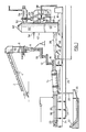
- garbage to be incinerated is stored in bales 2 which are fed by a conveyor 4 to a shredder 6 which shreds the material after which ferrous scrap such as baling wire is removed by a magnetic separator 8 and the remaining material is weighed on a belt scale 10 and conveyed by a vibratory or screw feeder 12 before being compressed and discharged into the upper end of an inclined rotary furnace 14 by means of a reciprocable ram feeder 16.
- the furnace 14 forms a primary combustor for the combustible content of the garbage.
- the furnace receives a mixture of hot air (or other oxygen containing gas) through pipes 18, 20 and 22 which terminate at different points lengthwise of the furnace, and receive hot air from line 24 and steam from line 26.
- the air is at about 500°C and the steam at about 400°C.
- the oxygen content of the air is deliberately insufficient to secure complete combustion of the combustible content of the garbage, but sufficient to maintain combustion reactions at a sufficient level to maintain a temperature of about 500°C to about 925°C, typically about 900°C, in the furnace and to decompose and volatilize most of said combustible and volatile material without causing sintering due to melting of the glass content, thus leaving unreactive residues such as ash, glass shards and non-ferrous metals to be discharged at the lower end of the furnace through a water sealed chute 28 into a feed box of a clarifier 30 in which the residues are washed and then discharged by a conveyor 32.
- An auxiliary burner 34 receiving natural gas and air from a blower 36 is used to bring the furnace 14 up to working temperature during start up.
- each of the pipes 18,20 and 22 (which may be more than three in number) is independently controlled by valves 23 and 25 responsive to temperature readings from thermocouples 17, 19 and 21 located in different part of the furnace so that local hot or cold spots can be corrected. Entry into the furnace of a substantial mass of either more highly combustible or relatively incombustible material could otherwise cause temperatures to rise or fall locally to unacceptable levels.
- Gases generated in the furnace 14 are discharged through a duct 38 which enters tangentially the bottom end of a lower chamber 40 defined in a vertical cylindrical reactor 42.
- the gas composition is adjusted in the duct 38 by successive additions of further gases, namely further air, typically at about 500°C, added in stages along the duct 38, together with recirculated exhaust gases, typically at about 250°C.
- the exhaust recirculation is used to moderate combustion temperatures in the chamber to a desired level low enough to inhibit the production of nitrogen oxides, yet high enough to melt residual glass particles which may remain entrained by the gases even after the cyclone separation effect produced by a gas vortex set up in the chamber 40.
- This vortex extends from the tangential bottom inlet through the duct 38 up to a top outlet through the duct 44.
- the temperature developed in the vortex is high enough and the retention time is sufficient to destroy any residues of potentially harmful organic compounds such as polychlorinated biphenyls and preventing any possible formation of dioxins.
- Gas temperatures in the chamber 40 should normally be in the range 1250°C-1550°C.
- An additional gas burner 46 is provided in the duct 38 to help attain desired working temperatures during start up. The amount of air added is such as to provide an excess of oxygen in the combustion gases.
- Hot gases from the duct 44 are applied to heat exchangers 48, which are preferably of the ceramic tube type in order to withstand the temperatures involved.
- the gases to be heated are passed through arrays of vertically extending ceramic tube assemblies located in two vertically spaced horizontal legs of the duct 44. This arrangement provides for approximately equal thermal expansion of both legs, thus simplifying structural design.
- each tube comprises an outer tube 47 suspended from and communicating with a header 49 at its top end, the tube being closed at its bottom end, and an inner smaller diameter tube 45 suspended from a separate header 43 and opening at its bottom end within a bottom portion of the outer tube so as to provide a path between the two headers.
- the hot gases in the duct pass over the outer surfaces of the outer tubes. Any residual suspended solid or liquid matter in the hot gases should strike the tubes and drain or fall to the bottom of the duct.
- the still hot gases from the duct 44 typically at 1000°C to 1250°C, re-enter the reactor 42 at the lower end of an upper chamber 50, again tangentially, and after vertical movement upward through the chamber 50, exit tangentially through duct 52 to a further heat exchanger 54.
- Ambient air is introduced into the upper chamber 50 through a port 56, both so as to produce a substantial excess of oxygen content in the gases and thus assist in completing combustion, and so as to reduce the gas temperature at the duct 52 from about 550°C to about 925°C, preferably about 700°C to 900°C.
- the heat exchanger 54 may thus be of conventional construction, and is used to prevent compressed gas, typically mainly air, in a first stage before further heating in the heat exchanger 48.
- the air enters the heat exchanger 54 through duct 56 at about 350°C, leaves duct 58 at about 700°C, and is further heated in the heat exchangers 48 to about 950°C, before leaving through a duct 60.
- the heat exchangers may for example be used to heat air or a gas mixture used to drive a turbine 61, the exhaust from this turbine providing the hot air or oxygen containing gas required for introduction into rotary furnace 14 and the duct 38.
- the steam required by the furnace 14 may be provided by a waste heat boiler which receives the exhaust gases from the heat exchanger 54 typically at about 450°C to 500°C, the steam being superheated by the turbine exhaust gases in a suitable heat exchanger.
- the reduction of the temperature of the gases occurring in the chamber 50 is such as to solidify any residual glass particles still remaining in the suspension, and such as to permit conventional construction of the heat exchanger 54.
- the tangential entry and exit of the gases and their vortical movement through the chamber assists in disentraining such particles, whilst their solidification should prevent fouling of the heat exchanger 54.
- the tower 42 is provided with a dump cap 62 at the top of chamber 50, which forms part of an emergency relief system in the event of a failure in a turbine system driven by hot gases produced by the apparatus. Such a failure may require a very rapid cut off of hot gas input to the turbine system, and dumping of the exhaust gases from the chamber 50 may then be necessary to protect the heat exchanger 54 and other downstream equipment from excessive temperatures. Since combustion should have been substantially completed and most solid material removed, such emergency dumping does not constitute a major pollution hazard.
- An exemplary system might receive 1920 lbs. of garbage per hour, having a recoverable heat yield of about 5584 BTU/lb., which would be heated in the furnace 14 with 3794 lbs/hr of turbine exhaust gases, essentially hot air containing in this example about 15% by weight of steam and possible minor additions of combustion gases, together with sufficient steam to maintain a desired reaction temperature in the furnace 14.
Landscapes
- Engineering & Computer Science (AREA)
- Mechanical Engineering (AREA)
- General Engineering & Computer Science (AREA)
- Gasification And Melting Of Waste (AREA)
- Processing Of Solid Wastes (AREA)
Applications Claiming Priority (2)
| Application Number | Priority Date | Filing Date | Title |
|---|---|---|---|
| US06/844,954 US4658736A (en) | 1986-03-27 | 1986-03-27 | Incineration of combustible waste materials |
| US844954 | 1986-03-27 |
Publications (2)
| Publication Number | Publication Date |
|---|---|
| EP0239281A2 true EP0239281A2 (de) | 1987-09-30 |
| EP0239281A3 EP0239281A3 (de) | 1988-10-19 |
Family
ID=25294051
Family Applications (1)
| Application Number | Title | Priority Date | Filing Date |
|---|---|---|---|
| EP87302050A Withdrawn EP0239281A3 (de) | 1986-03-27 | 1987-03-10 | Verbrennung von brennbaren Abfällen |
Country Status (3)
| Country | Link |
|---|---|
| US (1) | US4658736A (de) |
| EP (1) | EP0239281A3 (de) |
| CA (1) | CA1281238C (de) |
Cited By (2)
| Publication number | Priority date | Publication date | Assignee | Title |
|---|---|---|---|---|
| EP0381946A1 (de) * | 1989-02-09 | 1990-08-16 | ABB Management AG | Müllverbrennungsanlage und Verfahren zu Ihrem Betrieb |
| EP0455624A3 (en) * | 1990-05-02 | 1992-03-11 | Sgp-Va Energie- Und Umwelttechnik Gesellschaft M.B.H. | Method for burning dust-laden gases as well as a combustion chamber for use in such a process |
Families Citing this family (34)
| Publication number | Priority date | Publication date | Assignee | Title |
|---|---|---|---|---|
| US5376354A (en) * | 1987-10-16 | 1994-12-27 | Noell Abfall-Und Energietechnik Gmbh | Process for disposal of waste by combustion with oxygen |
| US4986197A (en) * | 1989-06-06 | 1991-01-22 | Kent John M | Apparatus for using hazardous waste to form non hazardous aggregate |
| US4922841A (en) * | 1988-09-14 | 1990-05-08 | Kent John M | Method and apparatus for using hazardous waste to form non-hazardous aggregate |
| USRE35219E (en) * | 1988-09-14 | 1996-04-30 | Marine Shale Processors, Inc. | Apparatus for using hazardous waste to form non-hazardous aggregate |
| DE3911481A1 (de) * | 1989-04-08 | 1990-10-11 | Otto Beteiligungs Und Verwaltu | Verfahren zur entsorgung von abfaellen |
| US5822881A (en) * | 1989-09-20 | 1998-10-20 | Romweber; Frank T. | Method for conditioning refuse |
| US5116363A (en) * | 1990-02-26 | 1992-05-26 | Romweber Frank T | Method and apparatus for conditioning refuse |
| US5086716B1 (en) * | 1990-04-30 | 1995-08-29 | Perma Fix Corp | System, apparatus and method for disposing of solid waste |
| US5133267A (en) * | 1991-10-01 | 1992-07-28 | Marine Shale Processors, Inc. | Method and apparatus for using hazardous waste to form non-hazardous aggregate |
| GB9121648D0 (en) * | 1991-10-11 | 1991-11-27 | D & C Eng Bv | A combustor apparatus |
| TW235335B (de) * | 1991-11-05 | 1994-12-01 | Mitsubishi Heavy Ind Ltd | |
| DE59205475D1 (de) * | 1991-11-29 | 1996-04-04 | Noell En Und Entsorgungstechni | Verfahren zur thermischen Verwertung von Abfallstoffen |
| DE19602399C2 (de) * | 1996-01-24 | 2000-08-24 | Basf Coatings Ag | Aufgabevorrichtung und -verfahren für die Verbrennung von Industrieabfällen |
| HN1998000031A (es) * | 1997-06-11 | 1999-06-10 | Basf Ag | Metodo y aparatos mejorados para recuperar la energia de desechos mediante combustion de los mismos hornos industriales . |
| TW455667B (en) * | 1999-09-02 | 2001-09-21 | Von Roll Umwelttechnik Ag | Chute of a feed system for a refuse incineration plant having a cutting apparatus |
| DE60132876T2 (de) * | 2001-01-02 | 2009-03-05 | Moriguchi, Kei | Heizofen |
| US7442035B2 (en) * | 2005-04-26 | 2008-10-28 | Gei Development, Llc | Gas induction bustle for use with a flare or exhaust stack |
| US8459984B2 (en) * | 2005-04-26 | 2013-06-11 | Heartland Technology Partners Llc | Waste heat recovery system |
| US8790496B2 (en) * | 2007-03-13 | 2014-07-29 | Heartland Technology Partners Llc | Compact wastewater concentrator and pollutant scrubber |
| US10005678B2 (en) | 2007-03-13 | 2018-06-26 | Heartland Technology Partners Llc | Method of cleaning a compact wastewater concentrator |
| US8801897B2 (en) * | 2007-03-13 | 2014-08-12 | Heartland Technology Partners Llc | Compact wastewater concentrator and contaminant scrubber |
| WO2008112793A1 (en) * | 2007-03-13 | 2008-09-18 | Gei Development Llc | Wastewater concentrator |
| US8679291B2 (en) | 2007-03-13 | 2014-03-25 | Heartland Technology Partners Llc | Compact wastewater concentrator using waste heat |
| US8741100B2 (en) | 2007-03-13 | 2014-06-03 | Heartland Technology Partners Llc | Liquid concentrator |
| US20090301054A1 (en) * | 2008-06-04 | 2009-12-10 | Simpson Stanley F | Turbine system having exhaust gas recirculation and reheat |
| EP2396279A4 (de) | 2009-02-12 | 2013-03-06 | Heartland Technology Partners | Kompakter abwasserkonzentrator unter verwendung von abwärme |
| WO2012100074A2 (en) | 2011-01-21 | 2012-07-26 | Heartland Technology Partners Llc | Condensation plume mitigation system for exhaust stacks |
| US9296624B2 (en) | 2011-10-11 | 2016-03-29 | Heartland Technology Partners Llc | Portable compact wastewater concentrator |
| US8808497B2 (en) | 2012-03-23 | 2014-08-19 | Heartland Technology Partners Llc | Fluid evaporator for an open fluid reservoir |
| US8741101B2 (en) | 2012-07-13 | 2014-06-03 | Heartland Technology Partners Llc | Liquid concentrator |
| US9199861B2 (en) | 2013-02-07 | 2015-12-01 | Heartland Technology Partners Llc | Wastewater processing systems for power plants and other industrial sources |
| US8585869B1 (en) | 2013-02-07 | 2013-11-19 | Heartland Technology Partners Llc | Multi-stage wastewater treatment system |
| JP6369161B2 (ja) * | 2013-12-13 | 2018-08-08 | 株式会社Ihi | タール改質炉 |
| WO2020243510A1 (en) | 2019-05-31 | 2020-12-03 | Heartland Technology Partners Llc | Harmful substance removal system and method |
Family Cites Families (8)
| Publication number | Priority date | Publication date | Assignee | Title |
|---|---|---|---|---|
| US3901766A (en) * | 1973-06-04 | 1975-08-26 | David E Smith | Method and apparatus for producing charcoal |
| US4037543A (en) * | 1976-02-27 | 1977-07-26 | Angelo James F | Pollution free combination carbonization apparatus and furnace |
| US4245571A (en) * | 1978-04-05 | 1981-01-20 | T R Systems, Inc. | Thermal reductor system and method for recovering valuable metals from waste |
| US4232614A (en) * | 1979-06-06 | 1980-11-11 | Dorr-Oliver Incorporated | Process of incineration with predrying of moist feed using hot inert particulates |
| US4273619A (en) * | 1979-11-19 | 1981-06-16 | Angelo Ii James F | Apparatus for continuously carbonizing and activating carbonaceous materials |
| DE3015290A1 (de) * | 1980-04-21 | 1981-10-29 | Werner & Pfleiderer, 7000 Stuttgart | Verfahren und anlage zum veraschen von klaerschlamm |
| US4395958A (en) * | 1981-12-21 | 1983-08-02 | Industronics, Inc. | Incineration system |
| IT1158514B (it) * | 1982-01-13 | 1987-02-18 | Tecnitalia Spa | Impianto di incenerimento di rifiuti con forno in equicorrente |
-
1986
- 1986-03-27 US US06/844,954 patent/US4658736A/en not_active Expired - Lifetime
-
1987
- 1987-03-10 EP EP87302050A patent/EP0239281A3/de not_active Withdrawn
- 1987-03-20 CA CA000532625A patent/CA1281238C/en not_active Expired - Lifetime
Cited By (2)
| Publication number | Priority date | Publication date | Assignee | Title |
|---|---|---|---|---|
| EP0381946A1 (de) * | 1989-02-09 | 1990-08-16 | ABB Management AG | Müllverbrennungsanlage und Verfahren zu Ihrem Betrieb |
| EP0455624A3 (en) * | 1990-05-02 | 1992-03-11 | Sgp-Va Energie- Und Umwelttechnik Gesellschaft M.B.H. | Method for burning dust-laden gases as well as a combustion chamber for use in such a process |
Also Published As
| Publication number | Publication date |
|---|---|
| US4658736A (en) | 1987-04-21 |
| EP0239281A3 (de) | 1988-10-19 |
| CA1281238C (en) | 1991-03-12 |
Similar Documents
| Publication | Publication Date | Title |
|---|---|---|
| US4658736A (en) | Incineration of combustible waste materials | |
| EP0823590B1 (de) | Verfahren und vorrichtung zur erzeugung von überhitztem dampf mittels wärme von abfallverbrennung | |
| US4753181A (en) | Incineration process | |
| US5584255A (en) | Method and apparatus for gasifying organic materials and vitrifying residual ash | |
| US3722433A (en) | Method and apparatus for waste incineration | |
| CN106642159A (zh) | 一种回转窑与等离子体气化协同资源化危废处理系统、处理方法 | |
| WO2002086389A1 (en) | Waste treatment apparatus and method | |
| US6199492B1 (en) | Process for melting down combustion residues into slag | |
| RU2002101479A (ru) | Способ и устройство для пиролиза и газификации отходов | |
| JPH10246416A (ja) | 火格子燃焼設備に由来するフライダストを熱的に処理するための方法と装置 | |
| EP0687855B1 (de) | Zirkulierender Wirbelschichtreaktor für minderwertige Brennstoffe | |
| PL165498B1 (pl) | Sposób i uklad do przetwarzania niebezpiecznych odpadów w bezpieczny aglomerat PL PL | |
| US5154128A (en) | Process for salvaging waste and device for preparing said waste | |
| US5749309A (en) | Process and apparatus for the thermal production of energy from waste material, particulary refuse | |
| US5385104A (en) | Method and apparatus for incinerating different kinds of solid and possibly liquid waste material | |
| EP0536268A1 (de) | Verfahren und vorrichtung zum verbrennen von feststoffabfällen und möglicherweise flüssigen abfällen verschiedener art. | |
| CZ21797A3 (en) | Fluidized bed reactor for heat treatment of waste substances | |
| US6849160B2 (en) | Method and device for heat treatment of waste products | |
| CN1111674C (zh) | 热处理垃圾的方法和设备 | |
| KR100340263B1 (ko) | 플라즈마 열분해/용융에 의한 고수분 함량 혼합 폐기물의 처리 장치 및 방법 | |
| US6125774A (en) | Industrial waste combustion process | |
| RU2229060C2 (ru) | Установка для термической переработки нефтешламов | |
| HUT73708A (en) | Method and apparatous for pyrolizing of wastes | |
| CN218645578U (zh) | 危险废物处理系统 | |
| CN218348670U (zh) | 危险废物处理系统的燃烧室 |
Legal Events
| Date | Code | Title | Description |
|---|---|---|---|
| PUAI | Public reference made under article 153(3) epc to a published international application that has entered the european phase |
Free format text: ORIGINAL CODE: 0009012 |
|
| AK | Designated contracting states |
Kind code of ref document: A2 Designated state(s): AT BE CH DE ES FR GB GR IT LI LU NL SE |
|
| PUAL | Search report despatched |
Free format text: ORIGINAL CODE: 0009013 |
|
| AK | Designated contracting states |
Kind code of ref document: A3 Designated state(s): AT BE CH DE ES FR GB GR IT LI LU NL SE |
|
| 17P | Request for examination filed |
Effective date: 19890318 |
|
| 17Q | First examination report despatched |
Effective date: 19900129 |
|
| STAA | Information on the status of an ep patent application or granted ep patent |
Free format text: STATUS: THE APPLICATION IS DEEMED TO BE WITHDRAWN |
|
| 18D | Application deemed to be withdrawn |
Effective date: 19900821 |