EP0239285A2 - Distributeurs doseurs - Google Patents
Distributeurs doseurs Download PDFInfo
- Publication number
- EP0239285A2 EP0239285A2 EP87302081A EP87302081A EP0239285A2 EP 0239285 A2 EP0239285 A2 EP 0239285A2 EP 87302081 A EP87302081 A EP 87302081A EP 87302081 A EP87302081 A EP 87302081A EP 0239285 A2 EP0239285 A2 EP 0239285A2
- Authority
- EP
- European Patent Office
- Prior art keywords
- cup
- spacer
- dip tube
- inside wall
- liquid
- Prior art date
- Legal status (The legal status is an assumption and is not a legal conclusion. Google has not performed a legal analysis and makes no representation as to the accuracy of the status listed.)
- Withdrawn
Links
- 125000006850 spacer group Chemical group 0.000 claims abstract description 29
- 239000007788 liquid Substances 0.000 claims abstract description 17
- 238000000465 moulding Methods 0.000 description 2
- 229920003023 plastic Polymers 0.000 description 2
- 239000004033 plastic Substances 0.000 description 2
- 241000239290 Araneae Species 0.000 description 1
- 101100293261 Mus musculus Naa15 gene Proteins 0.000 description 1
- 230000000903 blocking effect Effects 0.000 description 1
- 239000000645 desinfectant Substances 0.000 description 1
- 239000003599 detergent Substances 0.000 description 1
- 238000007865 diluting Methods 0.000 description 1
- 239000003814 drug Substances 0.000 description 1
- 229940079593 drug Drugs 0.000 description 1
- 239000003337 fertilizer Substances 0.000 description 1
- 239000004009 herbicide Substances 0.000 description 1
- 239000012263 liquid product Substances 0.000 description 1
- 238000004519 manufacturing process Methods 0.000 description 1
- 239000000463 material Substances 0.000 description 1
- 230000002093 peripheral effect Effects 0.000 description 1
- 239000000344 soap Substances 0.000 description 1
- YZHUMGUJCQRKBT-UHFFFAOYSA-M sodium chlorate Chemical compound [Na+].[O-]Cl(=O)=O YZHUMGUJCQRKBT-UHFFFAOYSA-M 0.000 description 1
- 238000005406 washing Methods 0.000 description 1
Images
Classifications
-
- G—PHYSICS
- G01—MEASURING; TESTING
- G01F—MEASURING VOLUME, VOLUME FLOW, MASS FLOW OR LIQUID LEVEL; METERING BY VOLUME
- G01F11/00—Apparatus requiring external operation adapted at each repeated and identical operation to measure and separate a predetermined volume of fluid or fluent solid material from a supply or container, without regard to weight, and to deliver it
- G01F11/28—Apparatus requiring external operation adapted at each repeated and identical operation to measure and separate a predetermined volume of fluid or fluent solid material from a supply or container, without regard to weight, and to deliver it with stationary measuring chambers having constant volume during measurement
- G01F11/286—Apparatus requiring external operation adapted at each repeated and identical operation to measure and separate a predetermined volume of fluid or fluent solid material from a supply or container, without regard to weight, and to deliver it with stationary measuring chambers having constant volume during measurement where filling of the measuring chamber is effected by squeezing a supply container that is in fluid connection with the measuring chamber and excess fluid is sucked back from the measuring chamber during relaxation of the supply container
Definitions
- This invention relates to a simple form of dispenser for enabling a user to measure out a predetermined quantity of liquid product.
- a dispenser in various horticultural and domestic situations, for example in adding liquid detergent to a washing machine of dishwasher, in diluting measured quantities of concentrated weedkiller or fertiliser or in dispensing liquid disinfectants or foodstuffs or medicines by the spoonful. Pouring from a bottle into a spoon or a small measuring cup is troublesome, inaccurate and often leads to spillage.
- Commercial measuring devices such as liquid soap dispensers or the spirit dispensers used in bars are expensive and complex.
- the aim of the present invention is to allow standard cups to be manufactured in a way that allows the volume which they are to measure to be selected at will subsequently. According to the invention this is achieved in that the cup is made of an internal shape that is not uniform in a vertical direction, the dip tube is movable within the cup, and the position of the top end of the dip tube (or, at least, of that part of it which determines the level of the liquid in the cup) is determined by a spacer which spans the interior of the cup and of which the vertical position is, by virtue of the non-uniform cross-section of the cup, determined by its size.
- the inside of the cup is of round cross-section and tapers in diameter from top to bottom; if a spacer in the form of a large perforated disc or spider is used, the spacer will jam in the top of the cup and the dip tube will therefore be able to extend up to the top, so that the whole of the volume of the cup is used. If this spacer is replaced by a smaller one it will jam further down the cup, pushing down the dip tube with it, and so the cup will measure out a correspondingly smaller volume.
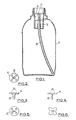
- a squeeze bottle 1 blow-moulded from a suitable plastics material has walls sufficiently thin to allow it to be deformed inwards easily by a user's hand.
- it In its neck it carries an upwardly open measuring cup 2 in the form of a rigid plastics moulding, with a flanged opening in its lower end to receive a dip tube 3.
- the neck of the container has an external screw thread to receive a cap, not shown.
- the dip tube 3 is a frictional fit in the lower end of the cup 2.
- the open upper end of the dip tube receives a spacer 4, shown in Figures 2 to 5, which has a number of holes 5 in it (four, in the example shown) and a flat spigot 6 on it underside by which it engages tightly in the top end of the dip tube, but without blocking the flow of liquid in the tube.
- the number and size of the holes in the spacer 4 is not important provided it allows free passage of the liquid; indeed it could instead be of spider-like form, or have peripheral notches instead of holes, as illustrated by the cloverleaf shape of the version shown in Figure 6.
- the metering dispenser described operates in a known manner, like those of the earlier patent applications referred to above; when there is liquid in the bottle and the user wishes to dispense a measured quantity he squeezes the bottle to force the liquid up the dip tube and into the cup 2. Provided he forces enough liquid up to fill the cup up to the level of the top end of the dip tube, or above it, then when he relaxes his grip any surplus liquid, above the level of the top of the tube, flows back down the tube and the volume of the liquid measured out is that of the cup up to the level of the top of the tube. He then pours this measured quantity out by tilting the bottle. As long as the pouring is done reasonable quickly there is no significant flow from the bottle itself during the time it is tilted.
- the measured quantity that could be dispensed was fixed by the geometry of the cup and the length of the dip tube.
- the inside of the cup 2 is tapered convergently downwards, in a series of steps 7 in the example shown, and the outer dimensions of the spacer 4 are such as to cause it to rest on one of the steps.
- the cup can be associated with three different sizes of spacer.
- Figure 1 the largest spacer is in place but, as indicated in broken lines, if it is replaced by a smaller spacer that smaller one would fit further down the cup, pushing the dip tube down with it, and then the cup would be suitable for measuring out a correspondingly smaller quantity of liquid.
- the measured volume of liquid in cubic centimetres associated with a given spacer is marked on the spacer, for example it may be in the form of embossed figures. In a typical case there may be spacers for measuring 10. 7.5 and 5cc.
- the cup is of circular cross-section in the example shown, it could be of different shape.
- three definite shoulders are shown, formed by the steps 7, it would be possible within the scope of the invention for the inside wall to be tapered continuously rather than in steps, or to be provided with or inwardly projecting lugs or steps which are not circumferentially continuous.
Landscapes
- Physics & Mathematics (AREA)
- Fluid Mechanics (AREA)
- General Physics & Mathematics (AREA)
- Closures For Containers (AREA)
- Containers And Packaging Bodies Having A Special Means To Remove Contents (AREA)
Applications Claiming Priority (2)
| Application Number | Priority Date | Filing Date | Title |
|---|---|---|---|
| GB8606051 | 1986-03-12 | ||
| GB868606051A GB8606051D0 (en) | 1986-03-12 | 1986-03-12 | Metering dispensers |
Publications (2)
| Publication Number | Publication Date |
|---|---|
| EP0239285A2 true EP0239285A2 (fr) | 1987-09-30 |
| EP0239285A3 EP0239285A3 (fr) | 1989-03-15 |
Family
ID=10594424
Family Applications (1)
| Application Number | Title | Priority Date | Filing Date |
|---|---|---|---|
| EP87302081A Withdrawn EP0239285A3 (fr) | 1986-03-12 | 1987-03-11 | Distributeurs doseurs |
Country Status (2)
| Country | Link |
|---|---|
| EP (1) | EP0239285A3 (fr) |
| GB (1) | GB8606051D0 (fr) |
Cited By (4)
| Publication number | Priority date | Publication date | Assignee | Title |
|---|---|---|---|---|
| US4951839A (en) * | 1989-02-07 | 1990-08-28 | Kong Cheung T | Measurement and dispensing unit |
| EP0552043A1 (fr) * | 1992-01-15 | 1993-07-21 | Peter Kalabakas | Dispositif de dosage |
| US5381930A (en) * | 1992-01-15 | 1995-01-17 | Kalabakas; Peter | Dispensing device for a measured volume of liquid |
| CN116732750A (zh) * | 2023-05-15 | 2023-09-12 | 重庆海尔滚筒洗衣机有限公司 | 一种衣物处理剂容器的盖体组件和衣物处理剂容器 |
Family Cites Families (2)
| Publication number | Priority date | Publication date | Assignee | Title |
|---|---|---|---|---|
| DE1075967B (de) * | 1956-05-07 | 1960-02-18 | Walter Schaedler | Elastische Dosierungs- und Transportflasche aus transparentem, elastischem Kunststoff |
| GB8325322D0 (en) * | 1983-09-21 | 1983-10-26 | Cope Allman Plastics Ltd | Metering dispensers |
-
1986
- 1986-03-12 GB GB868606051A patent/GB8606051D0/en active Pending
-
1987
- 1987-03-11 EP EP87302081A patent/EP0239285A3/fr not_active Withdrawn
Cited By (4)
| Publication number | Priority date | Publication date | Assignee | Title |
|---|---|---|---|---|
| US4951839A (en) * | 1989-02-07 | 1990-08-28 | Kong Cheung T | Measurement and dispensing unit |
| EP0552043A1 (fr) * | 1992-01-15 | 1993-07-21 | Peter Kalabakas | Dispositif de dosage |
| US5381930A (en) * | 1992-01-15 | 1995-01-17 | Kalabakas; Peter | Dispensing device for a measured volume of liquid |
| CN116732750A (zh) * | 2023-05-15 | 2023-09-12 | 重庆海尔滚筒洗衣机有限公司 | 一种衣物处理剂容器的盖体组件和衣物处理剂容器 |
Also Published As
| Publication number | Publication date |
|---|---|
| EP0239285A3 (fr) | 1989-03-15 |
| GB8606051D0 (en) | 1986-04-16 |
Similar Documents
| Publication | Publication Date | Title |
|---|---|---|
| US2804103A (en) | Bottle cap and measuring device | |
| US4606481A (en) | Dispensing closure for spouted container | |
| US4625897A (en) | Metering dispensers | |
| US3490290A (en) | Measuring device for mixed drinks | |
| US5044521A (en) | Volumetrically controlled drink dispenser | |
| US5186367A (en) | Measuring device for dispensing predetermined quantities of a liquid | |
| US2091929A (en) | Dispenser | |
| JP2634151B2 (ja) | 顆粒状物質用小分け器 | |
| US5884816A (en) | Liquid measuring device and method of using same | |
| US3643704A (en) | Device for collecting and selectively dispensing a flowable substance | |
| EP3580528B1 (fr) | Minuterie de dosage et distributeurs utilisant celle-ci | |
| US6966468B2 (en) | Dispenser with adjustable lateral powder flow | |
| US6343723B1 (en) | Measuring device for dispensing a predetermined quantity of liquid | |
| US6276572B1 (en) | Measuring device with conical cap | |
| WO1991000833A1 (fr) | Dispositif de dosage | |
| HK71397A (en) | Hollow body | |
| US5044527A (en) | Liquid dispensing system | |
| GB2067517A (en) | Metering dispensers | |
| US3599684A (en) | Container-dispenser unit | |
| US7032788B2 (en) | Metering device for container | |
| EP0239285A2 (fr) | Distributeurs doseurs | |
| EP0132875A2 (fr) | Dispositif verseur pour récipient contenant des liquides | |
| US3344962A (en) | Dispensing device | |
| RU2329030C2 (ru) | Мерное и выдачное устройство для прикрепления к колпачку на бутылке | |
| US4871095A (en) | Container for dispensing a measured amount of a granulated solid |
Legal Events
| Date | Code | Title | Description |
|---|---|---|---|
| PUAI | Public reference made under article 153(3) epc to a published international application that has entered the european phase |
Free format text: ORIGINAL CODE: 0009012 |
|
| AK | Designated contracting states |
Kind code of ref document: A2 Designated state(s): AT BE CH DE ES FR GB GR IT LI LU NL SE |
|
| PUAL | Search report despatched |
Free format text: ORIGINAL CODE: 0009013 |
|
| AK | Designated contracting states |
Kind code of ref document: A3 Designated state(s): AT BE CH DE ES FR GB GR IT LI LU NL SE |
|
| 17P | Request for examination filed |
Effective date: 19890818 |
|
| 17Q | First examination report despatched |
Effective date: 19901204 |
|
| STAA | Information on the status of an ep patent application or granted ep patent |
Free format text: STATUS: THE APPLICATION HAS BEEN WITHDRAWN |
|
| 18W | Application withdrawn |
Withdrawal date: 19910202 |
|
| R18W | Application withdrawn (corrected) |
Effective date: 19910202 |
|
| RIN1 | Information on inventor provided before grant (corrected) |
Inventor name: WORTLEY, MICHAEL JOHN |