EP0239308A2 - Liens pour câbles - Google Patents
Liens pour câbles Download PDFInfo
- Publication number
- EP0239308A2 EP0239308A2 EP87302295A EP87302295A EP0239308A2 EP 0239308 A2 EP0239308 A2 EP 0239308A2 EP 87302295 A EP87302295 A EP 87302295A EP 87302295 A EP87302295 A EP 87302295A EP 0239308 A2 EP0239308 A2 EP 0239308A2
- Authority
- EP
- European Patent Office
- Prior art keywords
- strap
- lug
- lugs
- cable tie
- free end
- Prior art date
- Legal status (The legal status is an assumption and is not a legal conclusion. Google has not performed a legal analysis and makes no representation as to the accuracy of the status listed.)
- Ceased
Links
Images

Classifications
-
- B—PERFORMING OPERATIONS; TRANSPORTING
- B65—CONVEYING; PACKING; STORING; HANDLING THIN OR FILAMENTARY MATERIAL
- B65D—CONTAINERS FOR STORAGE OR TRANSPORT OF ARTICLES OR MATERIALS, e.g. BAGS, BARRELS, BOTTLES, BOXES, CANS, CARTONS, CRATES, DRUMS, JARS, TANKS, HOPPERS, FORWARDING CONTAINERS; ACCESSORIES, CLOSURES, OR FITTINGS THEREFOR; PACKAGING ELEMENTS; PACKAGES
- B65D63/00—Flexible elongated elements, e.g. straps, for bundling or supporting articles
- B65D63/02—Metallic straps, tapes, or bands; Joints between ends thereof
- B65D63/06—Joints produced by application of separate securing members, e.g. by deformation thereof
- B65D63/08—Joints using buckles, wedges, or like locking members attached to the ends of the elements
-
- Y—GENERAL TAGGING OF NEW TECHNOLOGICAL DEVELOPMENTS; GENERAL TAGGING OF CROSS-SECTIONAL TECHNOLOGIES SPANNING OVER SEVERAL SECTIONS OF THE IPC; TECHNICAL SUBJECTS COVERED BY FORMER USPC CROSS-REFERENCE ART COLLECTIONS [XRACs] AND DIGESTS
- Y10—TECHNICAL SUBJECTS COVERED BY FORMER USPC
- Y10T—TECHNICAL SUBJECTS COVERED BY FORMER US CLASSIFICATION
- Y10T24/00—Buckles, buttons, clasps, etc.
- Y10T24/14—Bale and package ties, hose clamps
-
- Y—GENERAL TAGGING OF NEW TECHNOLOGICAL DEVELOPMENTS; GENERAL TAGGING OF CROSS-SECTIONAL TECHNOLOGIES SPANNING OVER SEVERAL SECTIONS OF THE IPC; TECHNICAL SUBJECTS COVERED BY FORMER USPC CROSS-REFERENCE ART COLLECTIONS [XRACs] AND DIGESTS
- Y10—TECHNICAL SUBJECTS COVERED BY FORMER USPC
- Y10T—TECHNICAL SUBJECTS COVERED BY FORMER US CLASSIFICATION
- Y10T24/00—Buckles, buttons, clasps, etc.
- Y10T24/14—Bale and package ties, hose clamps
- Y10T24/1457—Metal bands
-
- Y—GENERAL TAGGING OF NEW TECHNOLOGICAL DEVELOPMENTS; GENERAL TAGGING OF CROSS-SECTIONAL TECHNOLOGIES SPANNING OVER SEVERAL SECTIONS OF THE IPC; TECHNICAL SUBJECTS COVERED BY FORMER USPC CROSS-REFERENCE ART COLLECTIONS [XRACs] AND DIGESTS
- Y10—TECHNICAL SUBJECTS COVERED BY FORMER USPC
- Y10T—TECHNICAL SUBJECTS COVERED BY FORMER US CLASSIFICATION
- Y10T24/00—Buckles, buttons, clasps, etc.
- Y10T24/14—Bale and package ties, hose clamps
- Y10T24/1457—Metal bands
- Y10T24/148—End-to-end integral band end connection
Definitions
- This invention relates to cable ties, by which is meant a strapping device can be wrapped around cables, pipes or the like and secured in place by linking together the two ends of the cable tie.
- a very robust form of cable tie is required, such as for underwater intallations, where the cable tie may be subjected to rough conditions and corrosive effects.
- a metal cable tie covered with a protective coating may be needed.
- a problem then arises in securing the end of the strap of the cable tie after it has been wrapped around the article to which it is to be secured.
- this invention provides a cable tie comprising a plate with a projecting strap, the plate carrying on one face a first upstanding bridge portion defining a passageway generally aligned with the strap and of a width greater than the width of the strap, and a pair of lugs carried by upstanding lug supports to project in opposite directions inwardly towards the longitudinal centreline of the strap and the bridge portion, but which are displaced longitudinally with respect to one another to define a slot between them through which a free end portion of the strap, which has been wrapped round a cable, passed below the lugs and the bridge portion and bent back to overlie the bridge portion, can be manipulated to lie under one of the lugs, the width of the gap and the separation distance of the lug supports being such as to enable the free end portion of the strap to pass subsequently fully through the slot and then below the other lug so that when the free end of the strap is aligned with said longitudinal centreline, the free end portion of the strap will be held securely below both lugs.
- the formation and positioning of the lugs with respect to the plate and the strap enable the free end of the strap to be manipulated with relative ease to lie under both of the lugs whilst providing substantial security against accidental release of the strap from beneath the lugs.
- At least one of the lug supports lies in a vertical plane which points outwardly in the direction away from the bridge portion with respect to said longitudinal centreline. This makes is possible for the free end of the strap to be twisted slightly out of the normal longitudinal direction so as to be manipulated with ease beneath the lugs. The free end of the strap will then tend to lie in the normal longitudinal direction where it is even less likely to be released accidentally from beneath the lugs in view of the twisting action which would be required in order to move the free end of the strap into a position where it can move out through the slot.
- the free end of the first lug which is situated nearest to the bridge portion, defines an edge which lies parallel to the vertical plane of its support.
- the free end of the second lug will also define an edge which lies parallel to said edge of the first lug.
- the separation distance between the lug supports to be kept quite small and preferably this separation distance will be less than 1.5 times the width of the strap. Desirably also the separation distance between the lug supports will be less than the internal width of the bridge portion.
- the cable tie may incorporate a third lug having an upstanding portion only, which is located directly opposite the one of the pair of lugs which is positioned furthest from the bridge.
- the lugs will be pressed out from the body of the plate. Further portions of the plate may also be cut out to enhance flexibility of the plate.
- the cable tie shown in Figure 1 comprises a plate 1 from which projects a strap 2.
- the parts of the cable tie are formed from a robust metal although the strap 2 is resilient so that it can be wrapped around articles and bent as required for fixing purposes.
- a first bridge portion 3 is formed at one end of the plate 1 whilst at the other end there is provided a pair of upstanding lugs 4,5 which are displaced longitudinally with respect to one another and define a slot 6 between their free ends.
- the free end 7 of the strap is fed below the lugs 4,5 and the bridge portion 3, and is then bent back over the bridge portion 3.
- the remaining free end 7 of the strap is then twisted so that one edge can be slid through the slot 6 and below the first lug 4.
- the other edge of the strap can then be moved past the free edge of the other lug 5.
- the end of the strap is subsequently moved to lie in the normal longitudinal position it will be held beneath portions of the two lugs 4 and 5.
- the supports 8,9 for lugs 10,11 lie in vertical planes which point outwardly in the direction away from the bridge portion 3 with respect to the longitudinal centreline of the cable tie. This enables the free end of the strap 2 to be manipulated more easily beneath the two lugs 10,11 during the twisting and lowering operation.
- the way in which the free end 7 of the strap 2 is located below the lugs 10,11 is illustrated in Figure 4.
- the end of the plate 1 nearest to the bridge portion 3 incorporates a shallow depression 12 (Figure 3) within which is welded one end of the strap 2. From Figure 2 it can be seen that the lugs 10 and 11 and their supports 8 and 9 are pressed out from the plate 1 to leave slots 13,14.
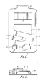
- Figures 5 and 6 comprise plan and end views of another form of cable tie of this invention.
- This cable tie is in many ways very similar to that shown in Figures 2 and 3 and has a plate 15 provided with an integral strap 2.
- the lug 16 nearest to the bridge portion 3 is more elongated, whilst the lug 17 is slightly truncated, as compared with the arrangement shown in Figure 2, resulting in a very near overlap of the two lugs, as can be seen from Figure 6.
- the lug 17 is situated in a lower plane than that of the lug 16. This arrangement creates a more secure fixing for the free end of the strap 2.
- the free end portion of the strap 2 needs to be twisted only slightly so as to slide under the lug 16 whereupon it can be lowered below the plane of the lug 17 and then eased below the lug 17.
- the distance between the free edge of the lug 17 and the support 18 for the lug 16 will be a little greater than the width of the strap 2 and it will be noted also that the support 18 and free edge 19 of the lug 17 extend in directions parallel to one another. It is anticipated that the lug 17 will be situated at a height which is only a little more than twice the thickness of the strap 2, for maximum security of the free end of the strap when located between the two lugs.
- the support 20 for the lug 17 is also angled (in a similar manner to that shown for lug 11 in Figures 2 and 4) but this is mainly for the purpose of providing a good lead in for the free end of the strap 2 as it makes its first pass below the lugs and the bridge portion 3.
- An additional advantageous feature is the provision of a further upstanding lug 21 which prevents undue lateral movement of the end of the strap 2 and also prevents the end of the strap from adopting an inclined attitude.
- the bridge portion 3 is positioned sufficiently inwardly of the edges of the plate 15 to avoid undue weakening in the tensile strength of the plate. Furthermore the effective width of the bridge 3 is only a little more than the width of the strap 2. The bridge 3 is also of a height comparable to that for the lug 17.
- a central portion 22 of the plate has been cut out to reduce the stiffness of the plate 15 so that the plate can readily be bent to provide a smooth contour of the cable tie around a bundle which is gripped by the tie.
- the cut outs from which bridge portion 3 and the lugs 16, 17 and 21 are formed additionally help in this respect.
Landscapes
- Engineering & Computer Science (AREA)
- Mechanical Engineering (AREA)
- Package Frames And Binding Bands (AREA)
- Finger-Pressure Massage (AREA)
- Basic Packing Technique (AREA)
- Massaging Devices (AREA)
- Clamps And Clips (AREA)
Applications Claiming Priority (4)
| Application Number | Priority Date | Filing Date | Title |
|---|---|---|---|
| GB868607379A GB8607379D0 (en) | 1986-03-25 | 1986-03-25 | Cable ties |
| GB8607379 | 1986-03-25 | ||
| GB8624054 | 1986-10-07 | ||
| GB868624054A GB8624054D0 (en) | 1986-10-07 | 1986-10-07 | Cable ties |
Publications (2)
| Publication Number | Publication Date |
|---|---|
| EP0239308A2 true EP0239308A2 (fr) | 1987-09-30 |
| EP0239308A3 EP0239308A3 (fr) | 1988-11-02 |
Family
ID=26290536
Family Applications (1)
| Application Number | Title | Priority Date | Filing Date |
|---|---|---|---|
| EP87302295A Ceased EP0239308A3 (fr) | 1986-03-25 | 1987-03-18 | Liens pour câbles |
Country Status (5)
| Country | Link |
|---|---|
| US (1) | US4750241A (fr) |
| EP (1) | EP0239308A3 (fr) |
| CA (1) | CA1274287C (fr) |
| GB (1) | GB2188363B (fr) |
| NO (1) | NO170862C (fr) |
Families Citing this family (9)
| Publication number | Priority date | Publication date | Assignee | Title |
|---|---|---|---|---|
| FR2613915B1 (fr) * | 1987-04-17 | 1989-09-22 | Cartier International | Nouveau dispositif de fixation reglable d'un bracelet, en particulier pour bracelet-montre |
| CA2357645A1 (fr) | 2000-09-25 | 2002-03-25 | Steve I. Szabo | Dispositif d'attache a collier pour cable |
| FR2818352B1 (fr) * | 2000-12-19 | 2003-04-18 | Caillau Ets | Collier de serrage |
| US20040200042A1 (en) * | 2003-04-14 | 2004-10-14 | Howell Frank A. | Rucksack rapid attachment buckle |
| US7263745B2 (en) * | 2005-08-02 | 2007-09-04 | Kenji Mori | Binding band |
| US7866005B2 (en) * | 2008-01-09 | 2011-01-11 | Panduit Corp. | Elastomeric releasable cable tie |
| US9009923B2 (en) * | 2012-04-02 | 2015-04-21 | Panduit Corp. | Cushion sleeve |
| US11703152B2 (en) | 2020-10-22 | 2023-07-18 | Panduit Corp. | Wrap bracket with strap mount |
| MX2023011373A (es) | 2021-03-31 | 2023-10-09 | Afl Telecommunications Llc | Abrazaderas de montaje de cables. |
Family Cites Families (15)
| Publication number | Priority date | Publication date | Assignee | Title |
|---|---|---|---|---|
| US580199A (en) * | 1897-04-06 | License-plate | ||
| US483040A (en) * | 1892-09-20 | Barbed strap for bunching lumber | ||
| US622687A (en) * | 1899-04-11 | Bicycle name-plate | ||
| US842240A (en) * | 1906-03-26 | 1907-01-29 | Will Z Searle | Package-tie. |
| US881053A (en) * | 1907-08-02 | 1908-03-03 | Alice Osborne Brigance | Bale-tie. |
| US912820A (en) * | 1907-11-21 | 1909-02-16 | Linford J Davis | Poultry-marker. |
| US995691A (en) * | 1909-11-22 | 1911-06-20 | Edgar Latham | Bale-tie. |
| US1084407A (en) * | 1913-11-17 | 1914-01-13 | Charles O Deist | Poultry-marker. |
| US1516682A (en) * | 1924-01-10 | 1924-11-25 | John A Peabody | Metallic tie |
| GB367440A (en) * | 1930-11-20 | 1932-02-22 | Daniel Ambrose Bradley | Improvements in or relating to fasteners for bands or straps |
| US2551384A (en) * | 1948-05-22 | 1951-05-01 | Earl F Middleton | Holding ring |
| GB1032303A (en) * | 1964-04-22 | 1966-06-08 | Allan Victor Shelley | Improvements relating to securing devices for thermal insulation |
| DE3017178C2 (de) * | 1980-05-05 | 1984-05-10 | Rasmussen Gmbh, 6457 Maintal | Schraublose Klemmschelle |
| EP0094168A1 (fr) * | 1982-05-06 | 1983-11-16 | Robert Arthur Henderson Heard | Agrafe pour le raccordement d'une bande |
| GB2168103B (en) * | 1984-12-11 | 1986-12-31 | Bowthorpe Hellermann Ltd | Tying device |
-
1987
- 1987-03-18 EP EP87302295A patent/EP0239308A3/fr not_active Ceased
- 1987-03-19 US US07/028,382 patent/US4750241A/en not_active Expired - Fee Related
- 1987-03-19 GB GB8706527A patent/GB2188363B/en not_active Expired - Lifetime
- 1987-03-20 NO NO871156A patent/NO170862C/no unknown
- 1987-03-20 CA CA532646A patent/CA1274287C/fr not_active Expired
Also Published As
| Publication number | Publication date |
|---|---|
| GB8706527D0 (en) | 1987-04-23 |
| CA1274287A (fr) | 1990-09-18 |
| NO170862C (no) | 1992-12-16 |
| CA1274287C (fr) | 1990-09-18 |
| GB2188363B (en) | 1990-03-21 |
| NO871156D0 (no) | 1987-03-20 |
| EP0239308A3 (fr) | 1988-11-02 |
| NO170862B (no) | 1992-09-07 |
| US4750241A (en) | 1988-06-14 |
| GB2188363A (en) | 1987-09-30 |
| NO871156L (no) | 1987-09-28 |
Similar Documents
| Publication | Publication Date | Title |
|---|---|---|
| US5687455A (en) | Releasable circular fastener | |
| US3908233A (en) | Releasable one-piece cable tie | |
| US4191334A (en) | Cable tie | |
| EP0971845B1 (fr) | Attache de cable en ligne | |
| US5488760A (en) | Inner lock band clamp | |
| US4750241A (en) | Cable ties | |
| EP0235997A1 (fr) | Attache de câble | |
| US5632457A (en) | Adjustable routing clamp assembly | |
| USRE31689E (en) | Cable tie | |
| US4261539A (en) | Adjustable clamping means for fastening elongated articles to a holding means | |
| US3966154A (en) | Cable hanger | |
| US4682748A (en) | One-piece clip-shaped holder for elongated articles | |
| KR101990778B1 (ko) | 재사용이 가능한 케이블 타이 | |
| EP0884738B1 (fr) | Dispositif de montage pour un faisceau de câblage | |
| EP1132315B1 (fr) | Dispositif pour lier des objets tels que des faisceaux de câbles | |
| EP0106861A1 (fr) | Dispositif de ligature de cables, conduites ou articles analogues, ensemble ou a des supports. | |
| AU580763B2 (en) | Buckle fastener | |
| US5915424A (en) | Guide tool for guiding a harnessing device underneath a plurality of wires disposed on a harness board | |
| EP4542060A1 (fr) | Fixation à verrou tournant | |
| US7334299B2 (en) | Device in a bundle tie | |
| NZ205187A (en) | Cable clamp with side aperture and wedge lock | |
| CN117465749A (zh) | 缆线捆扎件 | |
| EP0631345A1 (fr) | Dispositif d'atténuation de câble et méthode d'utilisation | |
| US1248973A (en) | Rope-holder. | |
| JP2024017659A (ja) | ベルトクランプ |
Legal Events
| Date | Code | Title | Description |
|---|---|---|---|
| PUAI | Public reference made under article 153(3) epc to a published international application that has entered the european phase |
Free format text: ORIGINAL CODE: 0009012 |
|
| AK | Designated contracting states |
Kind code of ref document: A2 Designated state(s): AT BE CH DE FR IT LI LU NL SE |
|
| 17P | Request for examination filed |
Effective date: 19880218 |
|
| PUAL | Search report despatched |
Free format text: ORIGINAL CODE: 0009013 |
|
| AK | Designated contracting states |
Kind code of ref document: A3 Designated state(s): AT BE CH DE FR IT LI LU NL SE |
|
| 17Q | First examination report despatched |
Effective date: 19900522 |
|
| STAA | Information on the status of an ep patent application or granted ep patent |
Free format text: STATUS: THE APPLICATION HAS BEEN REFUSED |
|
| 18R | Application refused |
Effective date: 19910816 |
|
| RIN1 | Information on inventor provided before grant (corrected) |
Inventor name: POWELL, TERENCE JOHN |