EP0239498B1 - Appareil de déplacement pour nettoyeur submergé - Google Patents
Appareil de déplacement pour nettoyeur submergé Download PDFInfo
- Publication number
- EP0239498B1 EP0239498B1 EP87400685A EP87400685A EP0239498B1 EP 0239498 B1 EP0239498 B1 EP 0239498B1 EP 87400685 A EP87400685 A EP 87400685A EP 87400685 A EP87400685 A EP 87400685A EP 0239498 B1 EP0239498 B1 EP 0239498B1
- Authority
- EP
- European Patent Office
- Prior art keywords
- inlet
- flow passage
- cleaner
- suction
- water
- Prior art date
- Legal status (The legal status is an assumption and is not a legal conclusion. Google has not performed a legal analysis and makes no representation as to the accuracy of the status listed.)
- Expired - Lifetime
Links
- 238000006073 displacement reaction Methods 0.000 title claims description 15
- XLYOFNOQVPJJNP-UHFFFAOYSA-N water Substances O XLYOFNOQVPJJNP-UHFFFAOYSA-N 0.000 claims description 30
- 239000007788 liquid Substances 0.000 claims description 10
- 230000009182 swimming Effects 0.000 claims description 4
- 238000004140 cleaning Methods 0.000 claims 1
- 230000000063 preceeding effect Effects 0.000 claims 1
- 230000000694 effects Effects 0.000 description 5
- 238000010586 diagram Methods 0.000 description 2
- 125000004122 cyclic group Chemical group 0.000 description 1
- 238000004146 energy storage Methods 0.000 description 1
- 238000012986 modification Methods 0.000 description 1
- 230000004048 modification Effects 0.000 description 1
- 230000002093 peripheral effect Effects 0.000 description 1
Images


Classifications
-
- E—FIXED CONSTRUCTIONS
- E04—BUILDING
- E04H—BUILDINGS OR LIKE STRUCTURES FOR PARTICULAR PURPOSES; SWIMMING OR SPLASH BATHS OR POOLS; MASTS; FENCING; TENTS OR CANOPIES, IN GENERAL
- E04H4/00—Swimming or splash baths or pools
- E04H4/14—Parts, details or accessories not otherwise provided for
- E04H4/16—Parts, details or accessories not otherwise provided for specially adapted for cleaning
- E04H4/1654—Self-propelled cleaners
- E04H4/1663—Self-propelled cleaners the propulsion resulting from an intermittent interruption of the waterflow through the cleaner
Definitions
- This invention relates to submersible swimming pool cleaners adapted to be connected to a treatment plant by a suction hose and in particular it relates to an apparatus for displacing the suction hose and/or the cleaner in order to free the cleaner from a submerged obstacle.
- Submersible suction cleaners of the kind adapted to move about in a swimming pool under the influence of kinetic energy imparted to the cleaner due to the intermittent variation in water flow through the cleaner may suffer from disadvantage that when the cleaner become stuck against an obstacle in the pool such as the steps, the normal driving mechanism of the cleaner may not be able to free the cleaner in order for it to continue on its random path. It may accordingly remain trapped until manually displaced.
- This device comprises a hollow dome-like member defining a central opening so that it may be mounted about the suction hose with the apex of the dome pointing away from the cleaner.
- the dome which is submerged in the water, causes a longitudinally pulsating hose to be displaced in a direction away from the cleaner, thereby pulling the cleaner away from the obstruction by the hose.
- Another known device comprises a sail carrying float adapted to be attached to the hose.
- the hose When the wind causes the float to sail, the hose is displaced which in turn causes the cleaner to be displaced and freed.
- this mechanism does not function efficiently.
- US-A 4 521 933 which is described in the preamble of claim 1 discloses a random steering device for a submerged suction cleaner. This device steers the cleaner randomly during its travel along a surface to be cleaned.
- the device comprises two inlets and an outlet with a suction hose connection.
- An inlet communicates to a compartment housing a water motor which drives a valve sectively opening and closing a port for communicating with an adjacent compartment.
- the hose will resist or store turning movement and the net effect is that the whole device turns around the axis of the connection immediately or at the occasion of a next rocking movement.
- the open port is closed the device should be facing a random new direction.
- the steering system of US-A 4 521 933 merely effects random changes of direction.
- US-A 3 384 914 discloses a pool vacuum comprising means for alternately changing the buoyancy of the apparatus to cause the apparatus alternately to submerge to the bottom of the pool or to rise to the surface.
- the actuating means for a valve in the sole inlet of the vacuum and which valve causes the changes in buoyancy of the apparatus comprises a combination of a turbine, gear train, capstan, bell-crank, operating lever, coil spring, flexible discs and a stretchable cord.
- the turbine is driven only when the valve is open and therefore to ensure cyclic operation of the apparatus an energy storage means defined by the stretchable cord is provided.
- the present invention concerns an apparatus for displacing a device such as a suction hose and/or a cleaner submersible in a liquid and movable in response to suction applied thereto, the apparatus comprising a body adapted to be connected to the device, the body defining first and second flow passages therethrough, the first flow passage extending between a first inlet to the body and an outlet therefrom, the second flow passage extending between a second inlet to the body and the said outlet, the outlet being adapted to be connected to a suction source so that suction is transmitted to the second inlet to the body, a valve assembly for opening and closing the first flow passage, and actuating means for operating the valve assembly and effecting intermittent opening and closing of the first flow passage, characterized in that the second inlet is adapted to be connected to the device for bringing the latter into communication with the suction source, and in that the apparatus further comprises drive means for propelling the apparatus from one location to another spaced location and thereby the device, in response to liquid flowing through the first flow passage when the valve
- the drive means may comprise a propeller connected to be driven by an impeller rotatably mounted near the first inlet and operative to drive the propeller when liquid is admitted through the first inlet.
- the valve assembly is preferably mounted at the first inlet and comprises a tubular body member having at least one circumferential hole therein and a sleeve member rotatably mounted upon the tubular body member, the sleeve member having at least one circumferential opening therein to register with the hole when the sleeve member is in a selected position thereby to admit liquid through the first inlet.
- the impeller is rotatably mounted in the valve body member.
- the actuating means may comprise a water driven member and a gear train connected at its input to the water driven member and at its output to the valve assembly.
- the water driven member may comprise a water wheel rotatably mounted in the body of the apparatus and a gear may be provided on the valve sleeve member which gear is adapted to be driven by the gear train.
- the displacement apparatus according to the invention may also comprise a float connectable to the body such that the propeller, in use, is maintained submerged in the liquid.
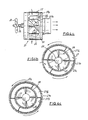
- a submersible displacement apparatus for a submersible suction cleaner is generally designated by the reference numeral 10 in figures 1 to 3.
- displacement apparatus 10 is connected to suction cleaner 100 by flexible suction hose 50 and to a treatment plant (not shown) by a similar hose 52.
- the cleaner 100 may be of the kind adapted to move about in a swimming pool 54 under the influence of kinetic energy imparted to the cleaner due to an intermittent variation in the flow of water through the cleaner.
- An example of such a cleaner is that disclosed in South African Patent no 75/1166 to F L 0 J Chauvier.
- the displacement apparatus comprises a body 11 defining a first flow passage 12, between a first inlet 13 and an outlet 14, for a stream of water flowing towards the treatment plant and a second flow passage 16, between a second inlet 15 and outlet 14.
- the body at the second inlet 15 and outlet 14 is adapted to be connected into hoses 50 and 52 so that the second flow passage 16 constitutes part of the flow path between cleaner 100 and the treatment plant.
- the flow path is mainly defined by suction hoses 50 and 52.
- the apparatus 10 is maintained in a submerged position just below the surface by means of a float 60 as shown in figure 1.
- the apparatus 10 also comprises drive means in the form of a propeller 20 for propelling the apparatus thereby to displace hose 50 and therefore cleaner 100 to free it from an obstacle, such as a step or the like, in pool 54 which it in the mean time may have encountered.
- drive means in the form of a propeller 20 for propelling the apparatus thereby to displace hose 50 and therefore cleaner 100 to free it from an obstacle, such as a step or the like, in pool 54 which it in the mean time may have encountered.
- An important feature of the displacement apparatus 10 according to the invention is that the stream of water flowing through the first inlet 13 via the first flow passage 12 to the treatment plant is utilised to drive the propeller 20 thereby to displace the hose.
- the apparatus will exert a force on the hose 50 while, when there is no flow of water through that flow passage, the apparatus will be inactive and floating about in pool 54 under the influence of cleaner 100, driven by its normal driving mechanism to move about in pool 54.
- valve assembly 17 which is associated with the first inlet 13 is also provided.
- This valve assembly is arranged alternately to open and close inlet 13. Accordingly, water will only be able to flow through first flow passage 12 when inlet 13 is open.
- Valve assembly 17 is further adapted to be open for periods substantially shorter than the periods during which it will be closed. Hence, propeller 20 will be caused to rotate for a short period during a cycle of the valve operation, which operation will be explained in more detail hereunder.
- valve assembly 17 comprises a tubular valve body 17b and a sleeve member 17a rotatably mounted upon body member 17b.
- Sleeve 17a defines two longitudinally extending and diametrically opposed slots 17c.
- Valve body 17b defines two diametrically opposed peripheral cavities 17d therein both leading to inlets 18 and which inlets communicate with the interior of the valve body where an impeller 21 is located.
- Impeller 21 is adapted to be driven by the stream of water entering through valve 17 and, in turn, to drive propeller 20 connected thereto by propeller shaft 22.
- Sleeve 17a is adapted rotatably to be driven about the valve body 17b thereby alternately to bring slots 17c and cavities 17d into and out of register.
- sleeve 17a is driven by a water wheel 28 (shown in figure 3), which is drivingly coupled via pinior 19a to a gear train 19 as shown in figure 2.
- Gear train 19 is adapted to mesh with and hence drive a gear 30 mounted at the inboard end of valve sleeve member 17a, adjacent the first inlet 13.
Landscapes
- Engineering & Computer Science (AREA)
- Architecture (AREA)
- Civil Engineering (AREA)
- Structural Engineering (AREA)
- Cleaning In General (AREA)
- Other Liquid Machine Or Engine Such As Wave Power Use (AREA)
Claims (10)
Applications Claiming Priority (2)
| Application Number | Priority Date | Filing Date | Title |
|---|---|---|---|
| ZA862317 | 1986-03-27 | ||
| ZA862317 | 1986-03-27 |
Publications (3)
| Publication Number | Publication Date |
|---|---|
| EP0239498A2 EP0239498A2 (fr) | 1987-09-30 |
| EP0239498A3 EP0239498A3 (en) | 1988-03-16 |
| EP0239498B1 true EP0239498B1 (fr) | 1990-10-31 |
Family
ID=25578343
Family Applications (1)
| Application Number | Title | Priority Date | Filing Date |
|---|---|---|---|
| EP87400685A Expired - Lifetime EP0239498B1 (fr) | 1986-03-27 | 1987-03-26 | Appareil de déplacement pour nettoyeur submergé |
Country Status (6)
| Country | Link |
|---|---|
| US (1) | US4789364A (fr) |
| EP (1) | EP0239498B1 (fr) |
| AU (1) | AU593338B2 (fr) |
| CA (1) | CA1272355A (fr) |
| DE (1) | DE3765816D1 (fr) |
| ES (1) | ES2019105B3 (fr) |
Families Citing this family (12)
| Publication number | Priority date | Publication date | Assignee | Title |
|---|---|---|---|---|
| EP0239497B1 (fr) * | 1986-03-27 | 1991-09-11 | Chauvier, Daniel Jean Valere Denis | Régulateur de courant de fluide |
| US4939806A (en) * | 1988-01-07 | 1990-07-10 | Liberty Pool Products S.A. | Pool cleaner |
| DE68902741D1 (de) * | 1988-01-07 | 1992-10-15 | Liberty Pool Prod | Schwimmbeckenreiniger. |
| US5099535A (en) * | 1988-02-18 | 1992-03-31 | Daniel J. D. Chauvier | Cleaner for submerged surfaces |
| CA2180398A1 (fr) * | 1995-07-07 | 1997-01-08 | Michael Edward Moore | Nettoyage de surfaces immergees |
| US6094764A (en) * | 1998-06-04 | 2000-08-01 | Polaris Pool Systems, Inc. | Suction powered pool cleaner |
| US7162763B2 (en) * | 2000-06-24 | 2007-01-16 | Henkin-Laby, Llc | Turbine drive apparatus and method suited for suction powered swimming pool cleaner |
| US20050251935A1 (en) * | 2002-03-15 | 2005-11-17 | Grobler Johannes S | Guiding apparatus for operating a pool cleaner |
| US20040074024A1 (en) * | 2002-10-19 | 2004-04-22 | H-Tech, Inc. | Suction-type cleaning device for submerged surfaces |
| CA2905794C (fr) | 2013-03-11 | 2018-02-27 | Pentair Water Pool And Spa, Inc. | Systeme de direction avec actionneur a deux roues et procede de nettoyage de piscine |
| EP2971410A4 (fr) | 2013-03-13 | 2017-03-22 | Pentair Water Pool and Spa, Inc. | Mécanisme à aubes alternées pour organe de nettoyage pour piscine |
| EP2971411A4 (fr) * | 2013-03-13 | 2017-04-19 | Pentair Water Pool and Spa, Inc. | Mécanisme à deux aubes pour appareil de nettoyage de piscine |
Family Cites Families (9)
| Publication number | Priority date | Publication date | Assignee | Title |
|---|---|---|---|---|
| US1689114A (en) * | 1925-03-03 | 1928-10-23 | Choquette John Albert | Auxiliary power means for ships and the like |
| US1735641A (en) * | 1928-06-25 | 1929-11-12 | Garcia Isidro | Marine turbine |
| US3229315A (en) * | 1963-12-05 | 1966-01-18 | Swimline Inc | Pool-cleaning device |
| US3384914A (en) * | 1966-11-16 | 1968-05-28 | Paul C. Wilhelmsen | Pool vacuum |
| GB1476366A (en) * | 1973-07-26 | 1977-06-10 | Peacock Investments Ltd | Method and apparatus for cleaning the surface of a liquid |
| US4007749A (en) * | 1975-04-07 | 1977-02-15 | Pansini Andrew L | Automatic pool cleaner system with timer device |
| US4040864A (en) * | 1976-03-12 | 1977-08-09 | Steeves Claire L | Device and method for cleaning leaves and debris from swimming pools |
| US4087286A (en) * | 1977-01-25 | 1978-05-02 | Airwick Pool Products, Inc. | Swimming pool cleaning device |
| AU551899B2 (en) * | 1981-09-24 | 1986-05-15 | Hayward Pool Products (Australia) Pty Ltd | Random steering suction cleaner |
-
1987
- 1987-03-26 EP EP87400685A patent/EP0239498B1/fr not_active Expired - Lifetime
- 1987-03-26 ES ES87400685T patent/ES2019105B3/es not_active Expired - Lifetime
- 1987-03-26 CA CA000533076A patent/CA1272355A/fr not_active Expired - Lifetime
- 1987-03-26 DE DE8787400685T patent/DE3765816D1/de not_active Expired - Lifetime
- 1987-03-26 US US07/030,132 patent/US4789364A/en not_active Expired - Lifetime
- 1987-03-26 AU AU70695/87A patent/AU593338B2/en not_active Ceased
Also Published As
| Publication number | Publication date |
|---|---|
| EP0239498A3 (en) | 1988-03-16 |
| ES2019105B3 (es) | 1991-06-01 |
| CA1272355A (fr) | 1990-08-07 |
| EP0239498A2 (fr) | 1987-09-30 |
| US4789364A (en) | 1988-12-06 |
| AU593338B2 (en) | 1990-02-08 |
| DE3765816D1 (de) | 1990-12-06 |
| AU7069587A (en) | 1987-10-01 |
Similar Documents
| Publication | Publication Date | Title |
|---|---|---|
| EP0239498B1 (fr) | Appareil de déplacement pour nettoyeur submergé | |
| US4746424A (en) | Floating swimming pool skimmer | |
| US3972339A (en) | Automatic swimming pool cleaner | |
| US6782578B1 (en) | Swimming pool pressure cleaner with internal steering mechanism | |
| US5985156A (en) | Automatic swimming pool cleaning system | |
| EP1749139B1 (fr) | Procede et dispositif de nettoyage de piscines | |
| US4790344A (en) | Fluid flow regulator | |
| US3936899A (en) | Automatic swimming pool cleaner | |
| US8555445B2 (en) | Hydraulic driven jaw-type clutch impeller combination and swimming pool bottom hydraulic pushed automatic cleaner comprising same | |
| USRE38479E1 (en) | Positive pressure automatic swimming pool cleaning system | |
| US3822754A (en) | Automatic swimming pool cleaner | |
| US6280611B1 (en) | Water suction powered automatic swimming pool cleaning system | |
| US4560418A (en) | Wheeled suction cleaners | |
| US4722110A (en) | Cleaning apparatus for a liquid containing vessel | |
| JPH0947735A (ja) | 水槽清浄機 | |
| US4193870A (en) | Pool cleaning system and apparatus | |
| EP0835357B1 (fr) | Systeme de nettoyage automatique de piscines | |
| EP2673429B1 (fr) | Nettoyeur de piscine à jet d'eau doté de propulseurs doubles opposés | |
| EP0323883B1 (fr) | Appareil pour le nettoyage de piscines | |
| CN112874773A (zh) | 空潜无人机 | |
| WO2014151086A2 (fr) | Nettoyeur de piscines à haute pression doté d'un mécanisme de décompte automatique du temps | |
| US4141101A (en) | Self propelled drivehead for automatic swimming pool cleaner | |
| WO2001092663A1 (fr) | Dispositif de nettoyage a air comprime pour piscine pourvu d'un mecanisme de guidage interne | |
| US3078617A (en) | Water toy | |
| CN118361139A (zh) | 用于清洁游泳池的具有双出口蜗壳的真空清洁器机器人 |
Legal Events
| Date | Code | Title | Description |
|---|---|---|---|
| PUAI | Public reference made under article 153(3) epc to a published international application that has entered the european phase |
Free format text: ORIGINAL CODE: 0009012 |
|
| AK | Designated contracting states |
Kind code of ref document: A2 Designated state(s): DE ES FR GB IT |
|
| PUAL | Search report despatched |
Free format text: ORIGINAL CODE: 0009013 |
|
| AK | Designated contracting states |
Kind code of ref document: A3 Designated state(s): DE ES FR GB IT |
|
| 17P | Request for examination filed |
Effective date: 19880530 |
|
| 17Q | First examination report despatched |
Effective date: 19890711 |
|
| GRAA | (expected) grant |
Free format text: ORIGINAL CODE: 0009210 |
|
| AK | Designated contracting states |
Kind code of ref document: B1 Designated state(s): DE ES FR GB IT |
|
| ITF | It: translation for a ep patent filed | ||
| REF | Corresponds to: |
Ref document number: 3765816 Country of ref document: DE Date of ref document: 19901206 |
|
| ET | Fr: translation filed | ||
| PLBE | No opposition filed within time limit |
Free format text: ORIGINAL CODE: 0009261 |
|
| STAA | Information on the status of an ep patent application or granted ep patent |
Free format text: STATUS: NO OPPOSITION FILED WITHIN TIME LIMIT |
|
| 26N | No opposition filed | ||
| ITTA | It: last paid annual fee | ||
| PGFP | Annual fee paid to national office [announced via postgrant information from national office to epo] |
Ref country code: GB Payment date: 20000303 Year of fee payment: 14 |
|
| PGFP | Annual fee paid to national office [announced via postgrant information from national office to epo] |
Ref country code: FR Payment date: 20000317 Year of fee payment: 14 |
|
| PGFP | Annual fee paid to national office [announced via postgrant information from national office to epo] |
Ref country code: ES Payment date: 20000322 Year of fee payment: 14 |
|
| PGFP | Annual fee paid to national office [announced via postgrant information from national office to epo] |
Ref country code: DE Payment date: 20000530 Year of fee payment: 14 |
|
| PG25 | Lapsed in a contracting state [announced via postgrant information from national office to epo] |
Ref country code: GB Free format text: LAPSE BECAUSE OF NON-PAYMENT OF DUE FEES Effective date: 20010326 |
|
| PG25 | Lapsed in a contracting state [announced via postgrant information from national office to epo] |
Ref country code: ES Free format text: LAPSE BECAUSE OF NON-PAYMENT OF DUE FEES Effective date: 20010327 |
|
| GBPC | Gb: european patent ceased through non-payment of renewal fee |
Effective date: 20010326 |
|
| PG25 | Lapsed in a contracting state [announced via postgrant information from national office to epo] |
Ref country code: FR Free format text: LAPSE BECAUSE OF NON-PAYMENT OF DUE FEES Effective date: 20011130 |
|
| REG | Reference to a national code |
Ref country code: FR Ref legal event code: ST |
|
| PG25 | Lapsed in a contracting state [announced via postgrant information from national office to epo] |
Ref country code: DE Free format text: LAPSE BECAUSE OF NON-PAYMENT OF DUE FEES Effective date: 20020101 |
|
| REG | Reference to a national code |
Ref country code: ES Ref legal event code: FD2A Effective date: 20030203 |
|
| PG25 | Lapsed in a contracting state [announced via postgrant information from national office to epo] |
Ref country code: IT Free format text: LAPSE BECAUSE OF NON-PAYMENT OF DUE FEES;WARNING: LAPSES OF ITALIAN PATENTS WITH EFFECTIVE DATE BEFORE 2007 MAY HAVE OCCURRED AT ANY TIME BEFORE 2007. THE CORRECT EFFECTIVE DATE MAY BE DIFFERENT FROM THE ONE RECORDED. Effective date: 20050326 |