EP0239786A2 - Réactance pour un dispositif de commutation haute puissance - Google Patents
Réactance pour un dispositif de commutation haute puissance Download PDFInfo
- Publication number
- EP0239786A2 EP0239786A2 EP87102636A EP87102636A EP0239786A2 EP 0239786 A2 EP0239786 A2 EP 0239786A2 EP 87102636 A EP87102636 A EP 87102636A EP 87102636 A EP87102636 A EP 87102636A EP 0239786 A2 EP0239786 A2 EP 0239786A2
- Authority
- EP
- European Patent Office
- Prior art keywords
- choke
- power supply
- conductor track
- spk
- chokes
- Prior art date
- Legal status (The legal status is an assumption and is not a legal conclusion. Google has not performed a legal analysis and makes no representation as to the accuracy of the status listed.)
- Granted
Links
Images
Classifications
-
- H—ELECTRICITY
- H01—ELECTRIC ELEMENTS
- H01F—MAGNETS; INDUCTANCES; TRANSFORMERS; SELECTION OF MATERIALS FOR THEIR MAGNETIC PROPERTIES
- H01F37/00—Fixed inductances not covered by group H01F17/00
Definitions
- the invention relates to a high-performance switching power supply according to the preamble of claim 1.
- Switched-mode power supplies have the essential advantage over conventional power supplies that they have a higher degree of efficiency with a lower weight and a smaller volume at a correspondingly lower cost. This is offset by the disadvantages of a somewhat more complicated switching technology, stronger RF interference and greater difficulties in smoothing the output voltage.
- the present invention is based on the object of finding a solution that is as optimal as possible also with regard to the necessary space and material requirements for improving smoothing and RF interference suppression in high-performance circuits.
- the arrangement according to the invention corresponds to a choke with two turns, without the winding material having to be wound with its correspondingly large cross section because of the high current strengths. Another advantage is the good suppression properties of the filter circuit due to the symmetrical structure.
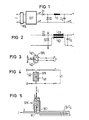
- the basic circuit diagram of a switched-mode power supply shown in FIG. 1 shows on the input side a line rectifier NGL with subsequent switching stage SST, which generates a square-wave voltage from the direct voltage by chopping and converts it with the aid of a transformer.
- the filter circuit consists of a smoothing choke L G switched on along the one output line and of a smoothing capacitor C G located in the shunt arm.
- Such a sieve circuit has the disadvantage that the HF interference radiation caused by the switching stage SST and symbolized by lightning arrows is only sufficiently reduced in the choke branch. In the second output line leading to the negative pole, which contains no smoothing choke, the RF interference radiation reaches the output unhindered.
- both chokes L G1 , L G2 each consist of one turn and, moreover, both turns are passed through the coil core SPK in the same winding direction. This means that the currents I flowing from point A to the positive pole or from the negative pole to point B add up through the coil core SPK.
- FIG. 5 A structure which is particularly advantageous for high-power switching power supplies for the filter chokes according to FIGS. 3 and 4 is shown in FIG. 5. It shows in perspective Representation of a conductor track assigned to the choke L G1 in the form of a copper strip.
- This copper strip is subdivided into three partial webs connected at one end, of which the middle partial web is guided as the first turn W1 through the bore of a tubular coil core SPK, while the two outer partial webs are returned on the outside of the core.
- These two outer partial tracks are extended beyond the core and, with their extended ends bent at right angles to the core axis, are connected to one of the two output terminals - here with the positive pole.
- the beginning of the middle partial web is also bent at right angles to the core axis and preferably in the opposite direction to the two outer partial webs.
- the conductor track assigned to the other choke L G2 is likewise a copper strip and, starting from the second output terminal, runs first between the two outer partial tracks of the other choke L G1 and then as a second turn W2 through the coil core SPK.
- the bent ends of the two outer sub-paths of inductor L G1 and the intermediate conductor path of inductor L G2 serve expediently as mounting surfaces for one or more smoothing capacitors C G connected in parallel.
Landscapes
- Engineering & Computer Science (AREA)
- Power Engineering (AREA)
- Power Conversion In General (AREA)
- Dc-Dc Converters (AREA)
- Details Of Television Scanning (AREA)
- Filters And Equalizers (AREA)
Priority Applications (1)
| Application Number | Priority Date | Filing Date | Title |
|---|---|---|---|
| AT87102636T ATE80493T1 (de) | 1986-02-28 | 1987-02-25 | Drossel fuer hochleistungs-schaltnetzteil. |
Applications Claiming Priority (2)
| Application Number | Priority Date | Filing Date | Title |
|---|---|---|---|
| DE3606592 | 1986-02-28 | ||
| DE3606592 | 1986-02-28 |
Publications (3)
| Publication Number | Publication Date |
|---|---|
| EP0239786A2 true EP0239786A2 (fr) | 1987-10-07 |
| EP0239786A3 EP0239786A3 (en) | 1988-10-12 |
| EP0239786B1 EP0239786B1 (fr) | 1992-09-09 |
Family
ID=6295208
Family Applications (1)
| Application Number | Title | Priority Date | Filing Date |
|---|---|---|---|
| EP87102636A Expired - Lifetime EP0239786B1 (fr) | 1986-02-28 | 1987-02-25 | Réactance pour un dispositif de commutation haute puissance |
Country Status (5)
| Country | Link |
|---|---|
| US (1) | US4791543A (fr) |
| EP (1) | EP0239786B1 (fr) |
| AT (1) | ATE80493T1 (fr) |
| DE (1) | DE3781578D1 (fr) |
| ES (1) | ES2033704T3 (fr) |
Cited By (3)
| Publication number | Priority date | Publication date | Assignee | Title |
|---|---|---|---|---|
| GB2243258A (en) * | 1990-04-20 | 1991-10-23 | Gold Star Co | Magnetron for microwave oven |
| US5493471A (en) * | 1992-07-04 | 1996-02-20 | Abb Patent Gmbh | Output capacitor array of a switched-mode power supply |
| DE102005037616A1 (de) * | 2005-08-09 | 2007-02-15 | Rohde & Schwarz Gmbh & Co. Kg | Leitungstransformator zur Impedanzanpassung |
Families Citing this family (2)
| Publication number | Priority date | Publication date | Assignee | Title |
|---|---|---|---|---|
| SE464001B (sv) * | 1989-06-20 | 1991-02-18 | Ericsson Telefon Ab L M | Glaettningsfilter foer en likriktare |
| US6874708B2 (en) * | 2003-02-13 | 2005-04-05 | Illinois Tool Works Inc. | Automatic air-assisted manifold mounted gun |
Family Cites Families (7)
| Publication number | Priority date | Publication date | Assignee | Title |
|---|---|---|---|---|
| DE486189C (de) * | 1929-11-12 | Siemens Schuckertwerke Akt Ges | Im Zuge der Hin- und Rueckleitung starker Stroeme liegende Drosselspule zur Erhoehung des induktiven Spannungsabfalls | |
| US3340458A (en) * | 1964-06-16 | 1967-09-05 | Roy M Keller | Filter choke with self-desaturating magnetic core |
| FR1422994A (fr) * | 1964-11-17 | 1966-01-03 | Circuit redresseur simple fournissant deux tensions continues symétriques | |
| US3611233A (en) * | 1969-08-14 | 1971-10-05 | Atomic Energy Commission | Pulse transformer using stripline windings |
| US3916286A (en) * | 1974-09-19 | 1975-10-28 | United Technologies Corp | Switching power supply common output filter |
| SU982163A1 (ru) * | 1981-03-24 | 1982-12-15 | Предприятие П/Я В-8466 | Конвертор |
| US4586120A (en) * | 1983-12-30 | 1986-04-29 | At&T Bell Laboratories | Current limit shutdown circuit with time delay |
-
1987
- 1987-02-25 DE DE8787102636T patent/DE3781578D1/de not_active Expired - Lifetime
- 1987-02-25 ES ES198787102636T patent/ES2033704T3/es not_active Expired - Lifetime
- 1987-02-25 AT AT87102636T patent/ATE80493T1/de not_active IP Right Cessation
- 1987-02-25 EP EP87102636A patent/EP0239786B1/fr not_active Expired - Lifetime
-
1988
- 1988-03-03 US US07/168,592 patent/US4791543A/en not_active Expired - Fee Related
Cited By (4)
| Publication number | Priority date | Publication date | Assignee | Title |
|---|---|---|---|---|
| GB2243258A (en) * | 1990-04-20 | 1991-10-23 | Gold Star Co | Magnetron for microwave oven |
| GB2243258B (en) * | 1990-04-20 | 1994-09-07 | Gold Star Co | Magnetron for microwave oven |
| US5493471A (en) * | 1992-07-04 | 1996-02-20 | Abb Patent Gmbh | Output capacitor array of a switched-mode power supply |
| DE102005037616A1 (de) * | 2005-08-09 | 2007-02-15 | Rohde & Schwarz Gmbh & Co. Kg | Leitungstransformator zur Impedanzanpassung |
Also Published As
| Publication number | Publication date |
|---|---|
| ATE80493T1 (de) | 1992-09-15 |
| EP0239786B1 (fr) | 1992-09-09 |
| ES2033704T3 (es) | 1993-04-01 |
| EP0239786A3 (en) | 1988-10-12 |
| US4791543A (en) | 1988-12-13 |
| DE3781578D1 (de) | 1992-10-15 |
Similar Documents
| Publication | Publication Date | Title |
|---|---|---|
| DE3325612C2 (fr) | ||
| DE3039530C2 (fr) | ||
| DE102006014608A1 (de) | Filterschaltung und Spannungsversorgungseinheit | |
| DE2406141A1 (de) | Aluminium-elektrolyt-kondensator niedrigen scheinwiderstandes und niedriger induktivitaet und seine verwendung | |
| DE102016201258A1 (de) | Elektrischer Spannungswandler mit mehreren Speicherdrosseln | |
| DE69006655T2 (de) | Generator zum Erzeugen einer elektrischen Spannung. | |
| EP0239786B1 (fr) | Réactance pour un dispositif de commutation haute puissance | |
| DE19829424A1 (de) | Gleichpoliges Filter | |
| DE102004008961B4 (de) | Spulenkörper für geschlossenen magnetischen Kern und daraus hergestellte Entstördrossel | |
| DE3881555T2 (de) | Gleichrichtertransformator. | |
| DE2418230C3 (de) | Kapazitiv gesteuerte Hochspannungswicklung aus Scheibenspulen für Transformatoren mit großen Leistungen | |
| CH491526A (de) | Elektrische Gleichrichteranlage | |
| DE8605501U1 (de) | Hochleistungs-Schaltnetzteil | |
| DE2640901A1 (de) | Impulstransformator hoher leistung | |
| DE3635365A1 (de) | Sekundaerseitig schaltbares netzgeraet | |
| DE3039549A1 (de) | Elektrischer uebertrager | |
| DE102023136766A1 (de) | Stromumrichter | |
| DE19741302A1 (de) | Geometrie für planare Induktivitäten | |
| DE3342011C2 (de) | Tiefpaßfilter für elektrische Verbraucher | |
| DE2036467C3 (de) | LC-Siebschaltung für Stromversorgungsgeräte mit Gleichspannungsausgang | |
| DE433752C (de) | Transformator mit einer Sekundaerwicklung aus spiralfoermig aufgewickelten bandfoermigen Leitern, deren Windungen durch isolierende Zwischenlagen voneinander getrennt sind | |
| DE2320589A1 (de) | Transformator mit wickelkern | |
| DE1121668B (de) | Anordnung zur Verbindung einer erdunsymmertrischen mit einer erdsymmetrischen Hochfrequenzanordnung | |
| DE69925973T2 (de) | Netzfilter | |
| EP0037970A2 (fr) | Transformateur de lignes pour un récepteur de télévision |
Legal Events
| Date | Code | Title | Description |
|---|---|---|---|
| PUAI | Public reference made under article 153(3) epc to a published international application that has entered the european phase |
Free format text: ORIGINAL CODE: 0009012 |
|
| AK | Designated contracting states |
Kind code of ref document: A2 Designated state(s): AT BE CH DE ES FR GB GR IT LI NL SE |
|
| PUAL | Search report despatched |
Free format text: ORIGINAL CODE: 0009013 |
|
| AK | Designated contracting states |
Kind code of ref document: A3 Designated state(s): AT BE CH DE ES FR GB GR IT LI NL SE |
|
| 17P | Request for examination filed |
Effective date: 19881108 |
|
| 17Q | First examination report despatched |
Effective date: 19901212 |
|
| RAP1 | Party data changed (applicant data changed or rights of an application transferred) |
Owner name: SIEMENS NIXDORF INFORMATIONSSYSTEME AG |
|
| GRAA | (expected) grant |
Free format text: ORIGINAL CODE: 0009210 |
|
| AK | Designated contracting states |
Kind code of ref document: B1 Designated state(s): AT BE CH DE ES FR GB GR IT LI NL SE |
|
| PG25 | Lapsed in a contracting state [announced via postgrant information from national office to epo] |
Ref country code: GR Free format text: LAPSE BECAUSE OF FAILURE TO SUBMIT A TRANSLATION OF THE DESCRIPTION OR TO PAY THE FEE WITHIN THE PRESCRIBED TIME-LIMIT Effective date: 19920909 |
|
| REF | Corresponds to: |
Ref document number: 80493 Country of ref document: AT Date of ref document: 19920915 Kind code of ref document: T |
|
| REF | Corresponds to: |
Ref document number: 3781578 Country of ref document: DE Date of ref document: 19921015 |
|
| ET | Fr: translation filed | ||
| ITF | It: translation for a ep patent filed | ||
| GBT | Gb: translation of ep patent filed (gb section 77(6)(a)/1977) | ||
| PG25 | Lapsed in a contracting state [announced via postgrant information from national office to epo] |
Ref country code: GB Effective date: 19930225 Ref country code: AT Effective date: 19930225 |
|
| PG25 | Lapsed in a contracting state [announced via postgrant information from national office to epo] |
Ref country code: SE Effective date: 19930226 Ref country code: ES Free format text: LAPSE BECAUSE OF NON-PAYMENT OF DUE FEES Effective date: 19930226 |
|
| PG25 | Lapsed in a contracting state [announced via postgrant information from national office to epo] |
Ref country code: LI Effective date: 19930228 Ref country code: CH Effective date: 19930228 Ref country code: BE Effective date: 19930228 |
|
| REG | Reference to a national code |
Ref country code: ES Ref legal event code: FG2A Ref document number: 2033704 Country of ref document: ES Kind code of ref document: T3 |
|
| PLBE | No opposition filed within time limit |
Free format text: ORIGINAL CODE: 0009261 |
|
| STAA | Information on the status of an ep patent application or granted ep patent |
Free format text: STATUS: NO OPPOSITION FILED WITHIN TIME LIMIT |
|
| BERE | Be: lapsed |
Owner name: SIEMENS NIXDORF INFORMATIONSSYSTEME A.G. Effective date: 19930228 |
|
| 26N | No opposition filed | ||
| PG25 | Lapsed in a contracting state [announced via postgrant information from national office to epo] |
Ref country code: NL Effective date: 19930901 |
|
| NLV4 | Nl: lapsed or anulled due to non-payment of the annual fee | ||
| GBPC | Gb: european patent ceased through non-payment of renewal fee |
Effective date: 19930225 |
|
| PG25 | Lapsed in a contracting state [announced via postgrant information from national office to epo] |
Ref country code: FR Effective date: 19931029 |
|
| REG | Reference to a national code |
Ref country code: CH Ref legal event code: PL |
|
| PG25 | Lapsed in a contracting state [announced via postgrant information from national office to epo] |
Ref country code: DE Effective date: 19931103 |
|
| REG | Reference to a national code |
Ref country code: FR Ref legal event code: ST |
|
| EUG | Se: european patent has lapsed |
Ref document number: 87102636.5 Effective date: 19930912 |
|
| REG | Reference to a national code |
Ref country code: ES Ref legal event code: FD2A Effective date: 19990201 |
|
| PG25 | Lapsed in a contracting state [announced via postgrant information from national office to epo] |
Ref country code: IT Free format text: LAPSE BECAUSE OF NON-PAYMENT OF DUE FEES;WARNING: LAPSES OF ITALIAN PATENTS WITH EFFECTIVE DATE BEFORE 2007 MAY HAVE OCCURRED AT ANY TIME BEFORE 2007. THE CORRECT EFFECTIVE DATE MAY BE DIFFERENT FROM THE ONE RECORDED. Effective date: 20050225 |