EP0240034A1 - Fixateur externe pour l'ostéosynthèse - Google Patents
Fixateur externe pour l'ostéosynthèse Download PDFInfo
- Publication number
- EP0240034A1 EP0240034A1 EP87105092A EP87105092A EP0240034A1 EP 0240034 A1 EP0240034 A1 EP 0240034A1 EP 87105092 A EP87105092 A EP 87105092A EP 87105092 A EP87105092 A EP 87105092A EP 0240034 A1 EP0240034 A1 EP 0240034A1
- Authority
- EP
- European Patent Office
- Prior art keywords
- clamping
- screw
- fixator according
- actuating
- cylindrical holding
- Prior art date
- Legal status (The legal status is an assumption and is not a legal conclusion. Google has not performed a legal analysis and makes no representation as to the accuracy of the status listed.)
- Granted
Links
- 210000000988 bone and bone Anatomy 0.000 claims abstract description 54
- 239000004033 plastic Substances 0.000 claims description 14
- 229920003023 plastic Polymers 0.000 claims description 14
- 239000000463 material Substances 0.000 claims description 7
- 238000002347 injection Methods 0.000 claims description 5
- 239000007924 injection Substances 0.000 claims description 5
- 238000005553 drilling Methods 0.000 claims description 2
- 230000004913 activation Effects 0.000 abstract 2
- 210000002414 leg Anatomy 0.000 description 12
- 210000002303 tibia Anatomy 0.000 description 6
- 230000008901 benefit Effects 0.000 description 5
- 230000004323 axial length Effects 0.000 description 3
- 239000004917 carbon fiber Substances 0.000 description 2
- 239000003365 glass fiber Substances 0.000 description 2
- OKTJSMMVPCPJKN-UHFFFAOYSA-N Carbon Chemical compound [C] OKTJSMMVPCPJKN-UHFFFAOYSA-N 0.000 description 1
- 229920000049 Carbon (fiber) Polymers 0.000 description 1
- 229910000831 Steel Inorganic materials 0.000 description 1
- 229910052799 carbon Inorganic materials 0.000 description 1
- 239000004918 carbon fiber reinforced polymer Substances 0.000 description 1
- 238000010276 construction Methods 0.000 description 1
- 239000000109 continuous material Substances 0.000 description 1
- 230000008878 coupling Effects 0.000 description 1
- 238000010168 coupling process Methods 0.000 description 1
- 238000005859 coupling reaction Methods 0.000 description 1
- 230000005489 elastic deformation Effects 0.000 description 1
- 210000003414 extremity Anatomy 0.000 description 1
- 239000000835 fiber Substances 0.000 description 1
- 239000007943 implant Substances 0.000 description 1
- 230000006872 improvement Effects 0.000 description 1
- 238000003780 insertion Methods 0.000 description 1
- 230000037431 insertion Effects 0.000 description 1
- 238000004519 manufacturing process Methods 0.000 description 1
- 239000002184 metal Substances 0.000 description 1
- VNWKTOKETHGBQD-UHFFFAOYSA-N methane Chemical compound C VNWKTOKETHGBQD-UHFFFAOYSA-N 0.000 description 1
- 230000004048 modification Effects 0.000 description 1
- 238000012986 modification Methods 0.000 description 1
- 239000002991 molded plastic Substances 0.000 description 1
- 210000004197 pelvis Anatomy 0.000 description 1
- 230000000750 progressive effect Effects 0.000 description 1
- 239000011343 solid material Substances 0.000 description 1
- 230000007480 spreading Effects 0.000 description 1
- 239000010959 steel Substances 0.000 description 1
Images


Classifications
-
- A—HUMAN NECESSITIES
- A61—MEDICAL OR VETERINARY SCIENCE; HYGIENE
- A61B—DIAGNOSIS; SURGERY; IDENTIFICATION
- A61B17/00—Surgical instruments, devices or methods
- A61B17/56—Surgical instruments or methods for treatment of bones or joints; Devices specially adapted therefor
- A61B17/58—Surgical instruments or methods for treatment of bones or joints; Devices specially adapted therefor for osteosynthesis, e.g. bone plates, screws or setting implements
- A61B17/60—Surgical instruments or methods for treatment of bones or joints; Devices specially adapted therefor for osteosynthesis, e.g. bone plates, screws or setting implements for external osteosynthesis, e.g. distractors, contractors
- A61B17/64—Devices extending alongside the bones to be positioned
- A61B17/6466—Devices extending alongside the bones to be positioned with pin-clamps movable along a solid connecting rod
-
- A—HUMAN NECESSITIES
- A61—MEDICAL OR VETERINARY SCIENCE; HYGIENE
- A61B—DIAGNOSIS; SURGERY; IDENTIFICATION
- A61B17/00—Surgical instruments, devices or methods
- A61B17/56—Surgical instruments or methods for treatment of bones or joints; Devices specially adapted therefor
- A61B17/58—Surgical instruments or methods for treatment of bones or joints; Devices specially adapted therefor for osteosynthesis, e.g. bone plates, screws or setting implements
- A61B17/60—Surgical instruments or methods for treatment of bones or joints; Devices specially adapted therefor for osteosynthesis, e.g. bone plates, screws or setting implements for external osteosynthesis, e.g. distractors, contractors
- A61B17/64—Devices extending alongside the bones to be positioned
- A61B17/645—Devices extending alongside the bones to be positioned comprising a framework
-
- F—MECHANICAL ENGINEERING; LIGHTING; HEATING; WEAPONS; BLASTING
- F16—ENGINEERING ELEMENTS AND UNITS; GENERAL MEASURES FOR PRODUCING AND MAINTAINING EFFECTIVE FUNCTIONING OF MACHINES OR INSTALLATIONS; THERMAL INSULATION IN GENERAL
- F16B—DEVICES FOR FASTENING OR SECURING CONSTRUCTIONAL ELEMENTS OR MACHINE PARTS TOGETHER, e.g. NAILS, BOLTS, CIRCLIPS, CLAMPS, CLIPS OR WEDGES; JOINTS OR JOINTING
- F16B43/00—Washers or equivalent devices; Other devices for supporting bolt-heads or nuts
- F16B43/02—Washers or equivalent devices; Other devices for supporting bolt-heads or nuts with special provisions for engaging surfaces which are not perpendicular to a bolt axis or do not surround the bolt
-
- F—MECHANICAL ENGINEERING; LIGHTING; HEATING; WEAPONS; BLASTING
- F16—ENGINEERING ELEMENTS AND UNITS; GENERAL MEASURES FOR PRODUCING AND MAINTAINING EFFECTIVE FUNCTIONING OF MACHINES OR INSTALLATIONS; THERMAL INSULATION IN GENERAL
- F16B—DEVICES FOR FASTENING OR SECURING CONSTRUCTIONAL ELEMENTS OR MACHINE PARTS TOGETHER, e.g. NAILS, BOLTS, CIRCLIPS, CLAMPS, CLIPS OR WEDGES; JOINTS OR JOINTING
- F16B7/00—Connections of rods or tubes, e.g. of non-circular section, mutually, including resilient connections
- F16B7/04—Clamping or clipping connections
-
- F—MECHANICAL ENGINEERING; LIGHTING; HEATING; WEAPONS; BLASTING
- F16—ENGINEERING ELEMENTS AND UNITS; GENERAL MEASURES FOR PRODUCING AND MAINTAINING EFFECTIVE FUNCTIONING OF MACHINES OR INSTALLATIONS; THERMAL INSULATION IN GENERAL
- F16B—DEVICES FOR FASTENING OR SECURING CONSTRUCTIONAL ELEMENTS OR MACHINE PARTS TOGETHER, e.g. NAILS, BOLTS, CIRCLIPS, CLAMPS, CLIPS OR WEDGES; JOINTS OR JOINTING
- F16B7/00—Connections of rods or tubes, e.g. of non-circular section, mutually, including resilient connections
- F16B7/04—Clamping or clipping connections
- F16B7/044—Clamping or clipping connections for rods or tubes being in angled relationship
- F16B7/048—Clamping or clipping connections for rods or tubes being in angled relationship for rods or for tubes without using the innerside thereof
- F16B7/0493—Clamping or clipping connections for rods or tubes being in angled relationship for rods or for tubes without using the innerside thereof forming a crossed-over connection
-
- A—HUMAN NECESSITIES
- A61—MEDICAL OR VETERINARY SCIENCE; HYGIENE
- A61B—DIAGNOSIS; SURGERY; IDENTIFICATION
- A61B17/00—Surgical instruments, devices or methods
- A61B17/16—Instruments for performing osteoclasis; Drills or chisels for bones; Trepans
- A61B17/17—Guides or aligning means for drills, mills, pins or wires
- A61B17/171—Guides or aligning means for drills, mills, pins or wires for external fixation
Definitions
- the invention relates to an external fixator for osteosynthesis, as described in the preamble of claim 1 and in the book “Current Concepts of External Fixation of Fractures”, published by Uhthoff and Stahl, published by Springer-Verlag Berlin Heidelberg New York 1982, s. there 99-103, is known.
- the known fixator contains two approximately circular cylindrical steel disks of the same circumference, which are coaxially penetrated by a common clamping screw. A thin friction disk can optionally be provided in the joint between the two clamping disks.
- a clamping disk of the pair of clamping disks has two approximately cylindrical bores which extend secantially and parallel to one another and penetrate the radial circular end face facing the adjacent clamping disk. This results in two receiving bores slotted longitudinally over a relatively large circumferential area, into which the fixator rods - projecting from the longitudinal slots on one side along the longitudinal side - have to be inserted axially.
- the cylindrical holding openings for receiving either a bone nail (e.g. one Steinmann-Nagels) or a bone screw (for example a Schanze screw) are also formed in the known fixator analogous to the described cylindrical bores for the fixator rods as one-sided longitudinally slotted cylindrical bores.
- a jamming of a fixator rod and a bone screw occurs in the known external fixator accordingly by tightening the central clamping screw in such a way that both clamping disks with their facing circular end faces are pressed axially against each other and thereby clamp the circumferential regions of the fixator rod and bone screw protruding from the longitudinal slots of the receiving bores between them.
- fixator external which is known from the book “Current Concepts of External Fixation of Fractures”, offers the advantage of a simple design comprising only a few components, as opposed to other fixators who are known from prior use, but is regarding its handling during the operation and the subsequent supply of the Patients in need of improvement.
- the invention lies on the basis of the external fixator described in the book "Current Concepts of External Fixation of Fractures" the task of improving the known external fixator in terms of handling while maintaining its advantageous simple design. This object is achieved in accordance with the characterizing part of claim 1.
- each cylindrical holding opening is formed by a one-piece connected reveal surface, which can be deformed elastically or plastically to such an extent by actuating a screw element that the cylindrical holding opening initially leading as a drilling or screwing gauge and - after progressive infeed or narrowing - as a clamping receptacle for the bone nail or for the bone screw.
- the first possibility of such an alternative according to the invention may consist in the fact that the cylindrical holding openings, when the actuating screws are tightened by elastic or plastic material deformation with respect to the bridging component, are initially deliverable in the sense of a pre-locking and each with an additional feed stroke of one
- the drill or screw guide can be deformed up to its end-of-jamming position with the bone nail or with the bone screw.
- the second possibility of such an alternative may be that the cylindrical holding openings, when the actuating screws are tightened, together with the adjacent holder-side clamping jaw surfaces by means of elastic or plastic material deformation, are initially deliverable in the sense of a pre-locking (with regard to the bridging component) and that the cylindrical ones Each of the holding openings can be deformed with an additional feed stroke that also locks the clamping jaw surfaces, from a drill or screw guide to its end-of-jamming position with the bone nail or with the bone screw.
- a preferred embodiment according to the invention can therefore advantageously be handled in practice as follows: a cylindrical holding opening is pre-locked - if appropriate together with adjacent jaw surfaces - by partially tightening the actuating screw. This means that the holder on the bridging component (e.g. on a fixation rod) is held essentially immovable and the cylindrical holding opening is positioned essentially immovably with respect to the bridging component or with respect to the holder carrying it.
- a bone drill (hereinafter, if necessary, a tap) and, after removing the bone or tap, a bone screw or a bone nail (the latter as an implant) can then be inserted through the cylindrical holding opening. As soon as the bone nail or the bone screw is fastened through the cylindrical holding opening and is in its end position within the bone, the rest of the delivery of the cylindrical holding opening takes place until it jams.
- fixator according to the invention represents a significant simplification in operational terms compared to the known.
- an external fixator is particularly advantageous if both the cylindrical holding opening (for successively receiving a drill and a bone screw or a bone nail) and the jaw surfaces of the associated holder are used with a single actuating screw, from the pre-locking to the end position locking , can be operated.
- the actuating screws can be designed as toggle screws provided with manually operable large handling surfaces.
- An elastic or plastic deformation of the cylindrical holding opening - optionally together with adjacent jaw surfaces for the bridging component - can be advantageously carried out if the components involved in the delivery consist of a suitable plastic.
- Such a plastic can be processed into an injection molded plastic part and in particular can be reinforced with carbon fiber or glass fiber.
- the use of plastics - possibly including the bridging components - in addition to simplifying and reducing the cost of manufacture and a lightweight construction, creates a desirable X-ray transparency, which is not the case with the metal fixators previously used.
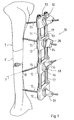
- an entire external fixator is designated by the reference number 10.
- the external fixator is shown using the example of a tibia designated T, in which F distance osteosynthesis is performed.
- the fixator 10 has two fixator rods 11 which are clamped in four brackets 12.
- Each holder 12 is provided with clamping jaw surfaces 13 for receiving the fixator rods 11.
- Components are provided for receiving the bone screws 15, as are shown, for example, in FIGS. 15 and 16. These components include washers 17, which are used for the spatial alignment of the bone screws 15.
- the rotatable washers 17 are provided in the region of their spherical surface 16 with an elongated hole 18 for receiving the screw shaft, not shown, of the actuating screw 14, which in turn contains the bone screw 15.
- the relative position of the brackets 12 on the bridging components is brought about by partially tightening the actuating screw 14 in question with its manual actuation knob 19. This partial suit also pre-locks the longitudinal axis y of each actuating screw in a desired spatial position.
- a bone drill is then axially passed through the front opening 20 (which merges into the cylindrical holding opening, not shown) of the actuating screw 14 in question, and the holding hole B is introduced into the tibia.
- a tap is then inserted through the opening 20 of the actuating screw 14 and the bone bore B is provided with an internal thread.
- the bone screw 15 is then inserted through the opening 20 of the actuating screw 14.
- the actuating screw 14 in question is manually used by means of the actuating knob 19.
- both the holder 12 on the associated fixator rod 11 and the bone screw 15 within the actuating screw 14 and finally also the space joint system (of which only the washer 17 is shown in FIG. 1) are relative to the fixator rod 11 firmly locked.
- the components shown there can also be used to create a frame fixator or a fixator in the manner of a spatial framework.
- additional brackets 12, not shown would be clamped on one side to the two fixator rods 11 and would serve as coupling members for further laterally adjacent fixator rods 11, not shown.
- holders 12 (with actuating screws 14) can also be arranged on diametrically opposite sides of the tibia T for holding Steinmann nails.
- the use of the fixator 10 is of course not limited to a tibia T, but is advantageously also possible with other extremities and the pelvis, possibly also across joints.
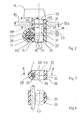
- the two-part holder 12 a has two clamps 21, 22.
- Each clamp 21, 22 has two mutually parallel clamp legs 23, 24 and 25, 26. Each two clamp legs 23, 24 and 25, 26 are connected to one another by a slotted tube region 27, 28.
- the slit tube region 27 of the clamp 22 forms the jaw surface 13 for the fixator rod 11 made of carbon fiber reinforced plastic.
- a slit sleeve 29 can be inserted into the jaw surface 13 to compensate for an undersize of the fixator rod.
- the slotted sleeve 29 accordingly forms a circumferentially variable fitting sleeve.
- the other clamp 21 contains the cylindrical holding opening 30 for receiving the bone screw 15.
- clamps 21 and 22 which each have only one slotted tube region 27 or 28, end of their two clamp legs 23, 24; 25, 26 are connected to one another in a one-piece, materially integral manner via a material bridge 31, 32.
- the material bridges 31, 32 serve to achieve defined clamping conditions.
- clamping legs 25, 26, 23, 24 Of the four successive clamping legs 25, 26, 23, 24, three clamping legs 25, 26, 23 each have a smooth through hole 33, 34, 35 and one clamping leg 24 has an internally threaded bore 36 for the threaded part 37 of the common actuating screw 14, which is used in the Embodiment according to FIGS. 2-4 the zylin dhariting opening 30 itself does not form.
- both the jaw surface 13 and the cylindrical holding bore 30 are operated together via the actuating screw 14.
- a pre-locking of the holder 12 a with respect to the fixator rod 11 and the bone screw 15 or with respect to a drill (not shown) is possible. Only when the actuating screw 14 is further pulled together does a fixed end position clamping of the fixator rod 11 occur with respect to the clamping jaw surface 13 or with respect to the slotted sleeve 29 and the bone screw 15 with respect to the cylindrical holding opening 30.
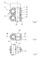
- a plan-serration so-called “Hirth serration”, which bears the reference number 38, is provided on the facing contact surfaces.
- two essentially identical clamps 22, 22 are provided, of which, however, the upper has two smooth through bores 35, while the lower clamp 21 has a smooth through bore 35 and an internally threaded bore 36.
- the two clamps 22, 22 each receiving a tubular fixator rod 11 are clamped analogously to the embodiment example according to FIGS. 2-4.
- a cylindrical holding opening 30 is not shown in the embodiment according to FIGS. 5-7, but it is readily conceivable that the actuating screw 14 contains a cylindrical holding opening 30, approximately analogously to the actuating screw 14 according to FIG. 8.
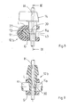
- the actuating screw 14 is penetrated by an axial cavity H, which contains the reveal surface L to form the cylindrical holding opening 30.
- this has an external cone K a .
- This outer cone K a is arranged approximately at the axial height of the cylindrical holding opening 30. If the actuating screw 14 is now tightened, the outer cone K increasingly rests against the outer surface of the fixator rod 11, whereby on the one hand the outer surface of the fixator rod 11 is pulled against the jaw surface 13 of the slotted tube region 27. On the other hand, the outer cone K itself - and thus the soffit surface L in the sense of a narrowing - is elastically deformed.
- the components 14 and the clamp bracket 12 b are made of an entropy-elastic deformable plastic, namely as injection molded parts.
- the actuating screw 14 is essentially identical.
- the outer cone K of the actuating screw 14 is provided with at least two clamping slots 39, which are intended to facilitate narrowing of the cylindrical holding opening 30 with the reveal L when the actuating screw 14 is tightened.
- the upper clamping leg 23 or 40 has a conical opening K i (inner cone) correlating with the outer cone K a.
- the respective lower clamping leg 24 or 41 is provided with the internal thread 36 for receiving the external thread G.
- FIGS. 11-12 differs arise in the embodiments according to FIGS. 11-12 only to the extent that FIGS. 11 and 12 each represent a double clamp arrangement for receiving two fixation rods 11, while FIG. 10 shows only a single clamp 12 d.
- the embodiment according to FIG. 12 has undivided slotted tube regions 27.
- the embodiment according to FIG. 11, on the other hand, has slotted tube regions 27 divided longitudinally by axial slots 42, so that in this case there are two approximately shell-shaped clamping components with the clamping legs 40, 41 and the divided ones Slotted tube regions 27 result.
- the embodiment according to FIG. 13 differs from that according to FIG. 12 only in that it does not have any slots 43 for defining a slot tube region 27. Rather, the mounting component 12 f forms push-through jaw openings 13, which allow the fixation rods 11 to be locked by means of separate stud screws 45 provided, for example, with toggle or knurled heads 44.
- the bone screw 15 is clamped within the cylindrical opening 30 via the press cone arrangement K a and K. analogous to the exemplary embodiment according to FIG. 12.
- the embodiment according to FIG. 14 with the mounting component 12 g forms a modification of the embodiment according to FIG. 12, but with the advantage of an articulated orientation and locking of the cylindrical holding opening 30 with its reveal L.
- the bracket 12 g is a bracket sided annular ball socket 46 is provided, in which a clamping ball 47 is articulated.
- a suitable plastic clamping ball 47 which consists of a suitable plastic clamping ball 47 has between a solid material bridge 48 to a radially extending lower slot 49, and a corresponding 90 0 circumferentially angularly offset radial upper slot 50th
- the clamping slots 49, 50 are intended to facilitate the deliverability in the region of the reveal surface L of the cylindrical holding opening 30. In the exemplary embodiment according to FIG. 14, this delivery takes place as follows:
- the actuating screw 14 provided with the axial cavity H has an inner cone K ii at its free end, which presses on the outside against the clamping ball 47 while the actuating screw 14 is tightened.
- the screw head of the actuating screw 14 is provided with insertion openings 60 for a plug-in tool.
- the screw axis y can also be oriented and fixed in space.
- the clamping ball 51 (FIG. 15) or clamping hemisphere 52 (FIG. 16) provided here is designed as a separate threaded part.
- the separate threaded parts 51, 52 are provided with the internal thread 36 for receiving the external thread part G of the actuating screw 14. So that the actuating screw 14 receiving the cylindrical holding opening 30 with the soffit L can be narrowed, the threaded part G has a clamping slot 39 in the axial length region of the soffit L.
- Each clamping leg 41 is provided with an annular ball socket 62 for receiving the ball 51 or the hemisphere 52.
- the washer 17 has a circular cylindrical basic shape and is rotatable in one circular cylindrical recess 53 arranged.
- the elongated hole (pivot opening) 18 is provided for the pivotability of the shaft of the screw 14.
- the spherical surface 16 accordingly forms the abutment for the underside 54 of the screw head 19.
- a combined locking is also in the sense of pre-locking both the cylindrical holding opening 30, the threaded parts 51 and 52 and the Fixator rods 11, not shown, possible within the jaw surfaces 13.
- brackets 12 j-12 m show plug-like inserts provided with contact flanges 61 for one receiving opening 55 (not shown in FIGS. 19 and 20) of an approximately plate-like or honeycomb-like bridging component 59.
- Each plug-like insert 12 j-12 m with internal thread 36 forms expansion bodies 56 with outer clamping jaw surfaces 64, which, possibly made easier by clamping slots 57, press against the wall of the receiving opening 55 when the actuating screw 14 is tightened.
- the actuating screw 14 according to FIG. 17 is provided not only with the threaded section G but also with an outer cone K a , which also has a deformation of the cylindrical holding opening 30 its reveal L causes. The same principle is followed in the embodiment according to FIG. 18.
- a roller-shaped threaded part 58 with an internal thread 36 for the external thread part G of the actuating screw 14 is provided within a circular cylindrical bearing socket 63 of the insert 12 1.
- the roller 58 has an inner cone K i , against which the outer cone K a of the actuating screw 14 strikes, causing both the elastic deformation of the clamping roller 58 and the narrowing of the cylindrical holding opening 30 and also a spreading of the expansion bodies 56.
- the holder 12 m as a separate threaded part with the internal thread 36 for the external thread G of the actuating screw 14 has a clamping hemisphere 52 which bears against the inner surface of the elastically deformable expansion body 56 forming a closed component K i can.
- the upper region of the component carrying the expansion body 56 has an elongated hole-like pivot opening 18 which is surrounded by a spherical surface 16 as an abutment for the underside 54 of the screw head 19.
- the threaded part G is also provided with a clamping slot 39 in the axial length region of the cylindrical holding opening 30.
- All plug-like embodiments according to FIGS. 17-20 have in common that the mobility of the components 58, 59 is supplemented by the rotatability of the inserts 12 1, 12 m within the cylindrical receptacle 55 of the honeycomb or plate-shaped bridging component 59 to allow room mobility.
Landscapes
- Health & Medical Sciences (AREA)
- Orthopedic Medicine & Surgery (AREA)
- Engineering & Computer Science (AREA)
- General Engineering & Computer Science (AREA)
- Life Sciences & Earth Sciences (AREA)
- Surgery (AREA)
- Mechanical Engineering (AREA)
- Biomedical Technology (AREA)
- Nuclear Medicine, Radiotherapy & Molecular Imaging (AREA)
- Heart & Thoracic Surgery (AREA)
- Medical Informatics (AREA)
- Molecular Biology (AREA)
- Animal Behavior & Ethology (AREA)
- General Health & Medical Sciences (AREA)
- Public Health (AREA)
- Veterinary Medicine (AREA)
- Surgical Instruments (AREA)
- Saccharide Compounds (AREA)
- Fats And Perfumes (AREA)
Priority Applications (1)
| Application Number | Priority Date | Filing Date | Title |
|---|---|---|---|
| AT87105092T ATE71502T1 (de) | 1986-04-04 | 1987-04-06 | Fixateur externe zur osteosynthese. |
Applications Claiming Priority (2)
| Application Number | Priority Date | Filing Date | Title |
|---|---|---|---|
| DE19863611319 DE3611319A1 (de) | 1986-04-04 | 1986-04-04 | Fixateur externe zur osteosynthese |
| DE3611319 | 1986-04-04 |
Publications (2)
| Publication Number | Publication Date |
|---|---|
| EP0240034A1 true EP0240034A1 (fr) | 1987-10-07 |
| EP0240034B1 EP0240034B1 (fr) | 1992-01-15 |
Family
ID=6297929
Family Applications (1)
| Application Number | Title | Priority Date | Filing Date |
|---|---|---|---|
| EP87105092A Expired - Lifetime EP0240034B1 (fr) | 1986-04-04 | 1987-04-06 | Fixateur externe pour l'ostéosynthèse |
Country Status (8)
| Country | Link |
|---|---|
| US (1) | US4920959A (fr) |
| EP (1) | EP0240034B1 (fr) |
| AT (1) | ATE71502T1 (fr) |
| CA (1) | CA1318820C (fr) |
| DE (2) | DE3611319A1 (fr) |
| ES (1) | ES2030008T3 (fr) |
| GR (1) | GR3003590T3 (fr) |
| WO (1) | WO1993012729A1 (fr) |
Cited By (12)
| Publication number | Priority date | Publication date | Assignee | Title |
|---|---|---|---|---|
| WO1990012547A1 (fr) * | 1989-04-18 | 1990-11-01 | Betz, Augustin | Systeme de fixation pour fractures d'os tubulaires |
| EP0408489A1 (fr) * | 1989-07-12 | 1991-01-16 | SULZER Medizinaltechnik AG | Implant pour la fixation de deux vertèbres |
| EP0517939A1 (fr) * | 1991-06-12 | 1992-12-16 | Fehling Mediprodukt Gmbh | Dispositif de fixation médical |
| FR2688685A1 (fr) * | 1992-03-19 | 1993-09-24 | Loniewski Xavier | Appareil orthopedique lineaire de fixation externe. |
| WO1993022984A1 (fr) * | 1992-05-15 | 1993-11-25 | Deszczyn & Cir & Ski Jaroslaw | Stabilisateur utilise dans le traitement d'os fractures |
| EP0596788A1 (fr) * | 1992-11-06 | 1994-05-11 | BIOMAT(S.a.r.l.) | Dispositif d'ostéosynthèse pour consolidation rachidienne |
| FR2701833A1 (fr) * | 1993-02-24 | 1994-09-02 | Garin Christophe | Fixateur pour les ostéosynthèses lombo-sacrées. |
| US5474553A (en) * | 1989-04-18 | 1995-12-12 | Rainer Baumgart | System for setting tubular bone fractures |
| US6149653A (en) * | 1997-09-05 | 2000-11-21 | Deslauriers; Richard J. | Self-retaining anchor track and method of making and using same |
| RU2187260C1 (ru) * | 2001-04-12 | 2002-08-20 | Новокузнецкий государственный институт усовершенствования врачей | Инструмент для репозиции скуловых дуг и костей |
| EP2774560A3 (fr) * | 2013-03-06 | 2014-11-12 | Stryker Trauma SA | Fixateur externe mini-rail |
| US10531896B2 (en) | 2015-08-10 | 2020-01-14 | Stryker European Holdings I, Llc | Distraction tube with wire clamp |
Families Citing this family (77)
| Publication number | Priority date | Publication date | Assignee | Title |
|---|---|---|---|---|
| DE3807335A1 (de) * | 1988-03-05 | 1989-09-14 | Orthoplant Endoprothetik | Repositions- und distraktionsgeraet |
| DE8805407U1 (de) * | 1988-04-23 | 1988-06-09 | Herzberg, Wolfgang, Dr. med., 2000 Wedel | Fixateur externe |
| CH683963A5 (de) * | 1988-06-10 | 1994-06-30 | Synthes Ag | Fixateur intern. |
| IT1228812B (it) * | 1989-03-22 | 1991-07-04 | Ortomedical S R L | Apparecchiatura per il fissaggio extrafocale per sintesi transossea di distrazioni e compressioni in ortopedia e traumatologia. |
| USD333184S (en) | 1990-02-23 | 1993-02-09 | Engineering & Precision Machining, Inc. | Pin clamp for use with an orthopedic appliance |
| USD334620S (en) | 1990-02-23 | 1993-04-06 | Engineering & Precision Machining, Inc. | Pin clamp for use with an orthopedic appliance |
| US5219349A (en) * | 1991-02-15 | 1993-06-15 | Howmedica, Inc. | Spinal fixator reduction frame |
| US5080661A (en) * | 1991-04-18 | 1992-01-14 | Hollister Incorporated | Fixation pin entry site dressing and method |
| US5318575A (en) * | 1992-02-03 | 1994-06-07 | United States Surgical Corporation | Method of using a surgical repair suture product |
| JP3382643B2 (ja) * | 1992-09-28 | 2003-03-04 | 長野計器株式会社 | スクリューピン取付け手術用テンプレート装置 |
| US5330489A (en) * | 1992-10-09 | 1994-07-19 | United States Surgical Corporation | Sternum closure buckle |
| US5417698A (en) * | 1992-10-09 | 1995-05-23 | United States Surgical Corporation | Apparatus for tightening elongated wound closure elements |
| US5355913A (en) * | 1992-10-09 | 1994-10-18 | United States Surgical Corporation | Surgical repair device |
| US5356412A (en) * | 1992-10-09 | 1994-10-18 | United States Surgical Corporation | Sternum buckle with rotational engagement and method of closure |
| US5947965A (en) | 1992-12-31 | 1999-09-07 | Bryan; Donald W. | Spinal fixation apparatus and method |
| US5306275A (en) * | 1992-12-31 | 1994-04-26 | Bryan Donald W | Lumbar spine fixation apparatus and method |
| US5498262A (en) * | 1992-12-31 | 1996-03-12 | Bryan; Donald W. | Spinal fixation apparatus and method |
| US5785709A (en) * | 1993-05-10 | 1998-07-28 | Hospital For Joint Diseases Orthopaedic Institute | Apparatus and method for performing a surgical procedure on bone lesions |
| US5496319A (en) * | 1994-06-27 | 1996-03-05 | Zimmer, Inc. | External fixation apparatus |
| GB9419408D0 (en) * | 1994-09-27 | 1994-11-09 | Newson Charles J | A bone fixing screw pin |
| FR2725613B1 (fr) * | 1994-10-12 | 1997-03-14 | Hardy Jean Marie | Fixateur externe applicable en orthopedie et en traumatologie |
| US5620443A (en) | 1995-01-25 | 1997-04-15 | Danek Medical, Inc. | Anterior screw-rod connector |
| US5562661A (en) * | 1995-03-16 | 1996-10-08 | Alphatec Manufacturing Incorporated | Top tightening bone fixation apparatus |
| US5662650A (en) * | 1995-05-12 | 1997-09-02 | Electro-Biology, Inc. | Method and apparatus for external fixation of large bones |
| IT1293941B1 (it) * | 1997-02-13 | 1999-03-11 | Orthofix Srl | Attrezzo ortopedico particolarmente per la correzione chirurgica di deformazioni ossee |
| FR2761256B1 (fr) | 1997-04-01 | 1999-06-11 | Daniel Chopin | Instrumentation d'osteosynthese rachidienne a connecteur de liaison entre une tige vertebrale et des organes d'ancrage osseux |
| WO2001012087A1 (fr) | 1999-08-12 | 2001-02-22 | Osteotech, Inc. | Dispositif d'accouplement tige/tige |
| WO2001035842A1 (fr) * | 1999-11-15 | 2001-05-25 | Synthes Ag Chur | Procede et dispositif pour la determination de parametres de reduction pour la reduction subsequente d'un os fracture |
| KR20020005339A (ko) * | 2000-07-06 | 2002-01-17 | 박찬협 | 안면골 골절 정복술시 골절편의 해부학적 정복 및 유지방법 |
| US7722645B2 (en) * | 2001-09-24 | 2010-05-25 | Bryan Donald W | Pedicle screw spinal fixation device |
| FR2835174B1 (fr) * | 2002-01-31 | 2004-03-19 | Materiel Orthopedique En Abreg | Connecteur pour dispositif d'osteosynthese rachidienne, ensemble connecteur/organe d'ancrage osseux et dispositif d'osteosynthese rachidienne utilisant cet ensemble |
| WO2005002450A2 (fr) * | 2003-06-30 | 2005-01-13 | Oguzhan Koroglu | Procede de production d'un dispositif de fixation externe, et notamment d'un fixateur d'ilizarov |
| EP1648318B1 (fr) * | 2003-07-29 | 2009-04-15 | Synthes GmbH | Dispositif pour fixer un support longitudinal a un element de fixation d'os |
| CN100473846C (zh) | 2004-03-10 | 2009-04-01 | 斯恩蒂斯有限公司 | 用于纵向构件相互定位的装置 |
| AU2004317510A1 (en) | 2004-03-10 | 2005-10-06 | Synthes Gmbh | External fixer for osteosynthesis |
| US8236028B2 (en) * | 2004-03-31 | 2012-08-07 | Depuy Spine Sarl | Spinal rod connector |
| ATE470460T1 (de) * | 2004-04-19 | 2010-06-15 | Synthes Gmbh | Elastisches element aus einem röntgenstrahlendurchlässigen material für eine medizinaltechnische vorrichtung |
| US20060155276A1 (en) * | 2005-01-11 | 2006-07-13 | Walulik Stephen B | Bone fixation assembly and related method |
| US9050142B2 (en) | 2005-01-18 | 2015-06-09 | DePuy Synthes Products, Inc. | Angularly stable device for mutually fixing a longitudinal carrier with a bone fixation element |
| US20060235383A1 (en) | 2005-03-07 | 2006-10-19 | Shane Hollawell | External fixator |
| US20060229605A1 (en) * | 2005-03-18 | 2006-10-12 | Olsen Ron A | Adjustable splint for osteosynthesis with incrementing assembly for adjustment in predetermined increments |
| US7588571B2 (en) * | 2005-03-18 | 2009-09-15 | Ron Anthon Olsen | Adjustable splint for osteosynthesis with modular joint |
| DE202005005444U1 (de) | 2005-04-01 | 2005-06-02 | Tantum Ag | Fixationseinrichtung zum stabilen Verbinden wenigstens zweier Knochenteile eines gebrochenen Knochens sowie Fixationselement und Bausatz |
| US8758343B2 (en) | 2005-04-27 | 2014-06-24 | DePuy Synthes Products, LLC | Bone fixation apparatus |
| US7803174B2 (en) * | 2005-11-04 | 2010-09-28 | Warsaw Orthopedic, Inc. | Dorsal adjusting multi-rod connector |
| US7731738B2 (en) | 2005-12-09 | 2010-06-08 | Orthopro, Llc | Cannulated screw |
| US8114080B2 (en) * | 2006-09-27 | 2012-02-14 | Depuy Products, Inc. | Flexible bone fixation device |
| US8277448B2 (en) * | 2007-03-07 | 2012-10-02 | Wright Medical Technology, Inc. | External fixation |
| US8419733B2 (en) * | 2007-08-16 | 2013-04-16 | Nutek Orthopedics, Inc. | External fixation apparatus with adjustable pin clamping means |
| JP5463574B2 (ja) * | 2007-09-27 | 2014-04-09 | ジンマー,インコーポレイティド | 創外固定及び安定化の方法及びクランプ装置 |
| CN103271761B (zh) | 2008-01-14 | 2015-10-28 | 康文图斯整形外科公司 | 用于骨折修补的装置和方法 |
| US8323292B2 (en) * | 2008-12-15 | 2012-12-04 | Spinecore, Inc. | Adjustable pin drill guide and methods therefor |
| US8657856B2 (en) * | 2009-08-28 | 2014-02-25 | Pioneer Surgical Technology, Inc. | Size transition spinal rod |
| FR2954905B1 (fr) | 2010-01-06 | 2012-12-28 | Implanet | Dispositif de fixation vertebrale |
| CN103517677B (zh) * | 2011-03-07 | 2017-06-20 | 康文图斯整形外科公司 | 用于骨修复制备的装置和方法 |
| US9247997B2 (en) * | 2011-09-30 | 2016-02-02 | Ethicon Endo-Surgery, Inc. | Patient-referenced surgical support frame |
| US9301783B2 (en) | 2013-01-23 | 2016-04-05 | Fixx Orthopedics, LLC | Orthopedic external fixation device |
| US20140257418A1 (en) * | 2013-03-07 | 2014-09-11 | Kyphon Sarl | Surgical tool holder |
| US9408635B2 (en) | 2013-03-15 | 2016-08-09 | Wright Medical Technology, Inc. | External fixation |
| EP2967674B1 (fr) | 2013-03-15 | 2024-02-21 | Biomet C.V. | Logement de pivot à axes multiples pour système de fixation externe |
| US9962188B2 (en) | 2013-10-29 | 2018-05-08 | Cardinal Health 247. Inc. | External fixation system and methods of use |
| BG112250A (bg) | 2014-02-06 | 2017-06-30 | Станислав Несторов | Затягащи съединения за универсалнимодулнисистеми заостеосинтеза |
| CN104274231A (zh) * | 2014-09-02 | 2015-01-14 | 苏州瑞华医院有限公司 | 一种治疗股骨干骨折的双轨型滑动接骨装置 |
| WO2016054262A2 (fr) * | 2014-10-01 | 2016-04-07 | Foot Innovations, Llc | Dispositif de fixation externe anatomique |
| WO2016138220A1 (fr) * | 2015-02-27 | 2016-09-01 | Thomas Gerold | Dispositif de fixation externe orthopédique |
| EP3210550B1 (fr) * | 2016-01-27 | 2018-10-10 | Biedermann Technologies GmbH & Co. KG | Ensemble de guidage d'instrument destiné à une place d'os et kit de plaque osseuse avec un tel ensemble de guidage |
| CN105686872B (zh) * | 2016-03-10 | 2019-02-05 | 成都新澳冠医疗器械有限公司 | 一种用于骨延长的桥接组合内固定系统 |
| DE102016117053A1 (de) | 2016-09-12 | 2018-03-15 | Aesculap Ag | Medizinisches Instrumentenführungssystem und Verfahren zum Herstellen eines medizinischen Instrumentenführungssystems |
| US10631881B2 (en) | 2017-03-09 | 2020-04-28 | Flower Orthopedics Corporation | Plating depth gauge and countersink instrument |
| WO2019010252A2 (fr) | 2017-07-04 | 2019-01-10 | Conventus Orthopaedics, Inc. | Appareil et méthodes de traitement d'os |
| IT201900007314A1 (it) | 2019-05-27 | 2020-11-27 | Orthofix Srl | Morsetto ad attacco rapido per sistemi di fissazione esterna |
| CN110559065B (zh) * | 2019-09-09 | 2022-01-18 | 王全 | 一种可调式胫骨高位截骨外固定器 |
| US11083506B1 (en) | 2020-02-10 | 2021-08-10 | DePuy Synthes Products, Inc. | Modular crimpable plate |
| CN112472262A (zh) * | 2020-12-11 | 2021-03-12 | 陈聚伍 | 单杆四钉骨折外固定架 |
| US11684390B2 (en) | 2021-01-07 | 2023-06-27 | DePuy Synthes Products, Inc. | Female polyaxial joint and method of using same |
| EP4346660A4 (fr) * | 2021-06-30 | 2025-07-09 | Mark A Dodson | Appareil d'ancrage |
| WO2025259517A1 (fr) * | 2024-06-10 | 2025-12-18 | Nutek Orthopaedics Inc. | Fixateur externe pour fracture du radius distal |
Citations (7)
| Publication number | Priority date | Publication date | Assignee | Title |
|---|---|---|---|---|
| FR782462A (fr) * | 1934-02-26 | 1935-06-05 | Simal Et A Legros D | Dispositif d'instrumentation pour ostéo-synthèse à tuteur externe |
| DE2929455A1 (de) * | 1978-07-20 | 1980-01-31 | Secr Social Service Brit | Einrichtung zur fixierung der bruchenden von gebrochenen gliedmassenknochen |
| GB2031731A (en) * | 1978-10-12 | 1980-04-30 | Knonner R F | Fracture reducing and joint immobilizing apparatus |
| FR2499400A1 (fr) * | 1981-02-06 | 1982-08-13 | Tornier Sa | Fixateur perfectionne pour fractures complexes, et notamment du type epiphysaire |
| FR2531332A1 (fr) * | 1982-08-04 | 1984-02-10 | Tesmoingt Patrice | Fixateur externe des os. plaque vissee percutanee |
| EP0140786A2 (fr) * | 1983-10-27 | 1985-05-08 | Societe De Realisations Electromecaniques (S.O.R.E.M.) | Appareils orthopediques pour immobiliser un os fracturé |
| GB2157179A (en) * | 1984-04-12 | 1985-10-23 | Mervyn Evans | Bone pin clamp for orthopaedic fracture fixation apparatus |
Family Cites Families (8)
| Publication number | Priority date | Publication date | Assignee | Title |
|---|---|---|---|---|
| US2391693A (en) * | 1943-12-09 | 1945-12-25 | Zimmer Mfg Company | Surgical splint |
| US2393694A (en) * | 1945-04-10 | 1946-01-29 | Otto S Kirschner | Surgical apparatus |
| DD140329A1 (de) * | 1978-12-13 | 1980-02-27 | Eberhard Schenk | Fixateur externe mit verstellbarer dritter dimension |
| SU984468A1 (ru) * | 1981-05-13 | 1982-12-30 | Омский медицинский институт | Компрессионно-дистракционный аппарат |
| US4483334A (en) * | 1983-04-11 | 1984-11-20 | Murray William M | External fixation device |
| US4475546A (en) * | 1983-06-23 | 1984-10-09 | Patton Stephen M | External fixation apparatus |
| DE8521997U1 (de) * | 1985-07-31 | 1985-10-24 | Aesculap-Werke Ag Vormals Jetter & Scheerer, 7200 Tuttlingen | Klammerfixateur zum Festlegen von in Knochenteile eingeschraubten Haltestiften |
| US4620533A (en) * | 1985-09-16 | 1986-11-04 | Pfizer Hospital Products Group Inc. | External bone fixation apparatus |
-
1986
- 1986-04-04 DE DE19863611319 patent/DE3611319A1/de active Granted
-
1987
- 1987-04-06 DE DE8787105092T patent/DE3775958D1/de not_active Expired - Lifetime
- 1987-04-06 AT AT87105092T patent/ATE71502T1/de not_active IP Right Cessation
- 1987-04-06 WO PCT/DE1987/000146 patent/WO1993012729A1/fr not_active Ceased
- 1987-04-06 US US07/138,381 patent/US4920959A/en not_active Expired - Fee Related
- 1987-04-06 ES ES198787105092T patent/ES2030008T3/es not_active Expired - Lifetime
- 1987-04-06 EP EP87105092A patent/EP0240034B1/fr not_active Expired - Lifetime
- 1987-05-14 CA CA000537183A patent/CA1318820C/fr not_active Expired - Fee Related
-
1992
- 1992-01-16 GR GR920400031T patent/GR3003590T3/el unknown
Patent Citations (7)
| Publication number | Priority date | Publication date | Assignee | Title |
|---|---|---|---|---|
| FR782462A (fr) * | 1934-02-26 | 1935-06-05 | Simal Et A Legros D | Dispositif d'instrumentation pour ostéo-synthèse à tuteur externe |
| DE2929455A1 (de) * | 1978-07-20 | 1980-01-31 | Secr Social Service Brit | Einrichtung zur fixierung der bruchenden von gebrochenen gliedmassenknochen |
| GB2031731A (en) * | 1978-10-12 | 1980-04-30 | Knonner R F | Fracture reducing and joint immobilizing apparatus |
| FR2499400A1 (fr) * | 1981-02-06 | 1982-08-13 | Tornier Sa | Fixateur perfectionne pour fractures complexes, et notamment du type epiphysaire |
| FR2531332A1 (fr) * | 1982-08-04 | 1984-02-10 | Tesmoingt Patrice | Fixateur externe des os. plaque vissee percutanee |
| EP0140786A2 (fr) * | 1983-10-27 | 1985-05-08 | Societe De Realisations Electromecaniques (S.O.R.E.M.) | Appareils orthopediques pour immobiliser un os fracturé |
| GB2157179A (en) * | 1984-04-12 | 1985-10-23 | Mervyn Evans | Bone pin clamp for orthopaedic fracture fixation apparatus |
Cited By (18)
| Publication number | Priority date | Publication date | Assignee | Title |
|---|---|---|---|---|
| US5474553A (en) * | 1989-04-18 | 1995-12-12 | Rainer Baumgart | System for setting tubular bone fractures |
| WO1990012547A1 (fr) * | 1989-04-18 | 1990-11-01 | Betz, Augustin | Systeme de fixation pour fractures d'os tubulaires |
| EP0408489A1 (fr) * | 1989-07-12 | 1991-01-16 | SULZER Medizinaltechnik AG | Implant pour la fixation de deux vertèbres |
| CH678803A5 (fr) * | 1989-07-12 | 1991-11-15 | Sulzer Ag | |
| US5084048A (en) * | 1989-07-12 | 1992-01-28 | Sulzer Brothers Limited | Implant for vertebrae with spinal stabilizer |
| EP0517939A1 (fr) * | 1991-06-12 | 1992-12-16 | Fehling Mediprodukt Gmbh | Dispositif de fixation médical |
| FR2688685A1 (fr) * | 1992-03-19 | 1993-09-24 | Loniewski Xavier | Appareil orthopedique lineaire de fixation externe. |
| WO1993018717A1 (fr) * | 1992-03-19 | 1993-09-30 | Xavier Loniewski | Appareil orthopedique lineaire de fixation externe |
| WO1993022984A1 (fr) * | 1992-05-15 | 1993-11-25 | Deszczyn & Cir & Ski Jaroslaw | Stabilisateur utilise dans le traitement d'os fractures |
| EP0596788A1 (fr) * | 1992-11-06 | 1994-05-11 | BIOMAT(S.a.r.l.) | Dispositif d'ostéosynthèse pour consolidation rachidienne |
| FR2697742A1 (fr) * | 1992-11-06 | 1994-05-13 | Biomat | Dispositif d'ostéosynthèse pour consolidation rachidienne. |
| FR2701833A1 (fr) * | 1993-02-24 | 1994-09-02 | Garin Christophe | Fixateur pour les ostéosynthèses lombo-sacrées. |
| US6149653A (en) * | 1997-09-05 | 2000-11-21 | Deslauriers; Richard J. | Self-retaining anchor track and method of making and using same |
| RU2187260C1 (ru) * | 2001-04-12 | 2002-08-20 | Новокузнецкий государственный институт усовершенствования врачей | Инструмент для репозиции скуловых дуг и костей |
| EP2774560A3 (fr) * | 2013-03-06 | 2014-11-12 | Stryker Trauma SA | Fixateur externe mini-rail |
| US9155561B2 (en) | 2013-03-06 | 2015-10-13 | Stryker Trauma Sa | Mini-rail external fixator |
| US9622781B2 (en) | 2013-03-06 | 2017-04-18 | Stryker European Holdings I, Llc | Mini-rail external fixator |
| US10531896B2 (en) | 2015-08-10 | 2020-01-14 | Stryker European Holdings I, Llc | Distraction tube with wire clamp |
Also Published As
| Publication number | Publication date |
|---|---|
| DE3611319A1 (de) | 1987-10-15 |
| ES2030008T3 (es) | 1992-10-16 |
| EP0240034B1 (fr) | 1992-01-15 |
| WO1993012729A1 (fr) | 1993-07-08 |
| CA1318820C (fr) | 1993-06-08 |
| US4920959A (en) | 1990-05-01 |
| GR3003590T3 (fr) | 1993-03-16 |
| DE3611319C2 (fr) | 1988-02-11 |
| ATE71502T1 (de) | 1992-02-15 |
| DE3775958D1 (en) | 1992-02-27 |
| DE3775958T (fr) | 1992-02-27 |
Similar Documents
| Publication | Publication Date | Title |
|---|---|---|
| EP0240034B1 (fr) | Fixateur externe pour l'ostéosynthèse | |
| DE69510854T2 (de) | Vorrichtung zur Befestigung eines spinalen Verbindungsstabes an einer Pedikelschraube | |
| EP0483242B1 (fr) | Element de reception d'une vis de pedicule, et vis de pedicule | |
| EP1274354B1 (fr) | Dispositif permettant la connexion articulee de deux corps | |
| DE19507141B4 (de) | Arretierwerkzeug | |
| EP1562499B1 (fr) | Dispositif de fixation orthopedique | |
| EP1235520B1 (fr) | Dispositif pour tendre ou comprimer des os ou des parties osseuses | |
| DE19848715C1 (de) | Osteosynthetisches Haltesystem | |
| EP0316371B1 (fr) | Dispositif de reduction pour colonne vertebrale | |
| EP1113757B1 (fr) | Instrument de reduction pour la fixation de fractures osseuses | |
| DE69116534T2 (de) | Äussere Fixatur zur Osteosynthese | |
| DE19534136A1 (de) | Externer oder interner Fixateur zur Wiederherstellung von Brüchen oder Arthroplastiken des Skeletts | |
| EP0011258A1 (fr) | Dispositif pour la fixation externe des fragments d'un os fracturé | |
| DE29922734U1 (de) | Vorrichtung für die Positionierung und Befestigung | |
| EP0388881A1 (fr) | Disposition pour la jonction de deux éléments en forme de bâton d'une prothése | |
| WO1998032386A1 (fr) | Dispositif pour connecter un support longitudinal avec une vis pediculaire | |
| DE29710979U1 (de) | Implantat zur Fixierung von Knochenteilen und Werkzeug für dieses Implantat | |
| EP0792628A2 (fr) | Endoprothèse pour une articulation artificielle de la hanche | |
| EP0314021A2 (fr) | Dispositif pour fixer des parties d'os | |
| EP0428874A2 (fr) | Elément de connexion pour structure tridimensionnelle faite de tubes et de noeuds | |
| DE3823746C2 (fr) | ||
| EP0500565B1 (fr) | Dispositif pour fixer un os | |
| CH686902A5 (de) | Klemmverbindung | |
| DE4136313C2 (de) | Äußere axiale Fixiervorrichtung | |
| DE4113083C2 (de) | Ringfixateur für die Osteosynthese |
Legal Events
| Date | Code | Title | Description |
|---|---|---|---|
| PUAI | Public reference made under article 153(3) epc to a published international application that has entered the european phase |
Free format text: ORIGINAL CODE: 0009012 |
|
| AK | Designated contracting states |
Kind code of ref document: A1 Designated state(s): AT BE CH DE ES FR GB GR IT LI LU NL SE |
|
| 17P | Request for examination filed |
Effective date: 19870910 |
|
| 17Q | First examination report despatched |
Effective date: 19900531 |
|
| ITF | It: translation for a ep patent filed | ||
| GRAA | (expected) grant |
Free format text: ORIGINAL CODE: 0009210 |
|
| AK | Designated contracting states |
Kind code of ref document: B1 Designated state(s): AT BE CH DE ES FR GB GR IT LI LU NL SE |
|
| REF | Corresponds to: |
Ref document number: 71502 Country of ref document: AT Date of ref document: 19920215 Kind code of ref document: T |
|
| GBT | Gb: translation of ep patent filed (gb section 77(6)(a)/1977) | ||
| ET | Fr: translation filed | ||
| REF | Corresponds to: |
Ref document number: 3775958 Country of ref document: DE Date of ref document: 19920227 |
|
| REG | Reference to a national code |
Ref country code: ES Ref legal event code: FG2A Ref document number: 2030008 Country of ref document: ES Kind code of ref document: T3 |
|
| PLBE | No opposition filed within time limit |
Free format text: ORIGINAL CODE: 0009261 |
|
| STAA | Information on the status of an ep patent application or granted ep patent |
Free format text: STATUS: NO OPPOSITION FILED WITHIN TIME LIMIT |
|
| REG | Reference to a national code |
Ref country code: GR Ref legal event code: FG4A Free format text: 3003590 |
|
| 26N | No opposition filed | ||
| PGFP | Annual fee paid to national office [announced via postgrant information from national office to epo] |
Ref country code: GR Payment date: 19940331 Year of fee payment: 8 Ref country code: GB Payment date: 19940331 Year of fee payment: 8 |
|
| PGFP | Annual fee paid to national office [announced via postgrant information from national office to epo] |
Ref country code: BE Payment date: 19940413 Year of fee payment: 8 |
|
| PGFP | Annual fee paid to national office [announced via postgrant information from national office to epo] |
Ref country code: DE Payment date: 19940419 Year of fee payment: 8 |
|
| PGFP | Annual fee paid to national office [announced via postgrant information from national office to epo] |
Ref country code: ES Payment date: 19940421 Year of fee payment: 8 |
|
| PGFP | Annual fee paid to national office [announced via postgrant information from national office to epo] |
Ref country code: AT Payment date: 19940426 Year of fee payment: 8 |
|
| PGFP | Annual fee paid to national office [announced via postgrant information from national office to epo] |
Ref country code: FR Payment date: 19940427 Year of fee payment: 8 |
|
| PGFP | Annual fee paid to national office [announced via postgrant information from national office to epo] |
Ref country code: SE Payment date: 19940428 Year of fee payment: 8 |
|
| PGFP | Annual fee paid to national office [announced via postgrant information from national office to epo] |
Ref country code: NL Payment date: 19940430 Year of fee payment: 8 Ref country code: LU Payment date: 19940430 Year of fee payment: 8 |
|
| PGFP | Annual fee paid to national office [announced via postgrant information from national office to epo] |
Ref country code: CH Payment date: 19940519 Year of fee payment: 8 |
|
| EPTA | Lu: last paid annual fee | ||
| EAL | Se: european patent in force in sweden |
Ref document number: 87105092.8 |
|
| PG25 | Lapsed in a contracting state [announced via postgrant information from national office to epo] |
Ref country code: LU Free format text: LAPSE BECAUSE OF NON-PAYMENT OF DUE FEES Effective date: 19950406 Ref country code: GB Effective date: 19950406 Ref country code: AT Effective date: 19950406 |
|
| PG25 | Lapsed in a contracting state [announced via postgrant information from national office to epo] |
Ref country code: SE Effective date: 19950407 Ref country code: ES Free format text: LAPSE BECAUSE OF NON-PAYMENT OF DUE FEES Effective date: 19950407 |
|
| PG25 | Lapsed in a contracting state [announced via postgrant information from national office to epo] |
Ref country code: LI Effective date: 19950430 Ref country code: CH Effective date: 19950430 Ref country code: BE Effective date: 19950430 |
|
| BERE | Be: lapsed |
Owner name: WITZEL ULRICH Effective date: 19950430 |
|
| PG25 | Lapsed in a contracting state [announced via postgrant information from national office to epo] |
Ref country code: GR Free format text: THE PATENT HAS BEEN ANNULLED BY A DECISION OF A NATIONAL AUTHORITY Effective date: 19951031 |
|
| PG25 | Lapsed in a contracting state [announced via postgrant information from national office to epo] |
Ref country code: NL Effective date: 19951101 |
|
| GBPC | Gb: european patent ceased through non-payment of renewal fee |
Effective date: 19950406 |
|
| REG | Reference to a national code |
Ref country code: CH Ref legal event code: PL |
|
| PG25 | Lapsed in a contracting state [announced via postgrant information from national office to epo] |
Ref country code: FR Effective date: 19951229 |
|
| REG | Reference to a national code |
Ref country code: GR Ref legal event code: MM2A Free format text: 3003590 |
|
| NLV4 | Nl: lapsed or anulled due to non-payment of the annual fee |
Effective date: 19951101 |
|
| PG25 | Lapsed in a contracting state [announced via postgrant information from national office to epo] |
Ref country code: DE Effective date: 19960103 |
|
| EUG | Se: european patent has lapsed |
Ref document number: 87105092.8 |
|
| REG | Reference to a national code |
Ref country code: FR Ref legal event code: ST |
|
| REG | Reference to a national code |
Ref country code: ES Ref legal event code: FD2A Effective date: 19990201 |
|
| PG25 | Lapsed in a contracting state [announced via postgrant information from national office to epo] |
Ref country code: IT Free format text: LAPSE BECAUSE OF NON-PAYMENT OF DUE FEES;WARNING: LAPSES OF ITALIAN PATENTS WITH EFFECTIVE DATE BEFORE 2007 MAY HAVE OCCURRED AT ANY TIME BEFORE 2007. THE CORRECT EFFECTIVE DATE MAY BE DIFFERENT FROM THE ONE RECORDED. Effective date: 20050406 |